Page 334 of 1659

5. Disconnect dial gauge and reinstall plug bolt with new
washer.
:14-20Nzm (1.4 - 2.0 kg-m, 10 - 14 ft-lb)
6. Connect injection tubes.
Flare nut:
:20-25Nzm (2.0 - 2.5 kg-m, 14 - 18 ft-lb)
7. Bleed air from fuel system.
Refer to EC-191.
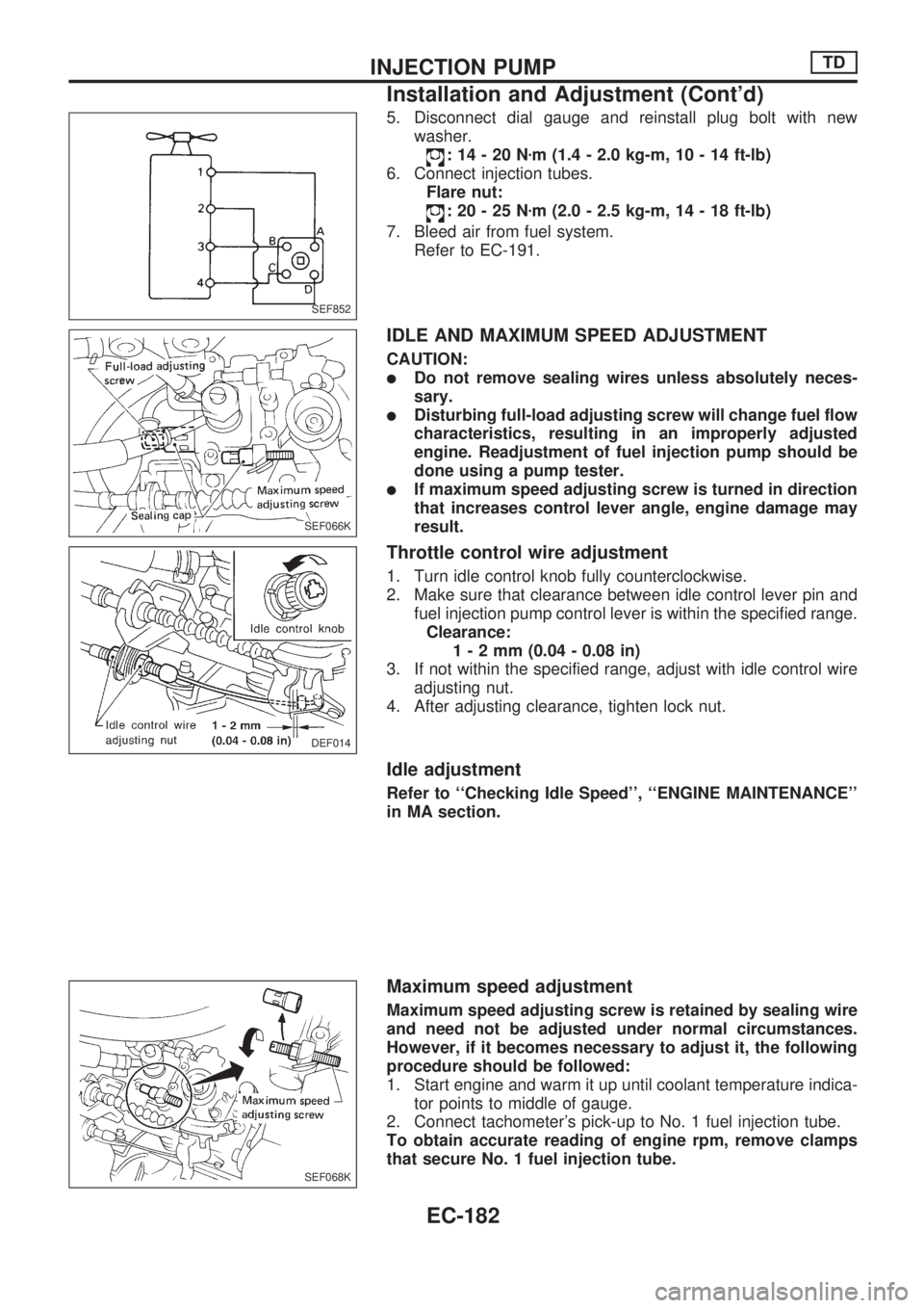
IDLE AND MAXIMUM SPEED ADJUSTMENT
CAUTION:
lDo not remove sealing wires unless absolutely neces-
sary.
lDisturbing full-load adjusting screw will change fuel flow
characteristics, resulting in an improperly adjusted
engine. Readjustment of fuel injection pump should be
done using a pump tester.
lIf maximum speed adjusting screw is turned in direction
that increases control lever angle, engine damage may
result.
Throttle control wire adjustment
1. Turn idle control knob fully counterclockwise.
2. Make sure that clearance between idle control lever pin and
fuel injection pump control lever is within the specified range.
Clearance:
1-2mm(0.04 - 0.08 in)
3. If not within the specified range, adjust with idle control wire
adjusting nut.
4. After adjusting clearance, tighten lock nut.
Idle adjustment
Refer to ``Checking Idle Speed'', ``ENGINE MAINTENANCE''
in MA section.
Maximum speed adjustment
Maximum speed adjusting screw is retained by sealing wire
and need not be adjusted under normal circumstances.
However, if it becomes necessary to adjust it, the following
procedure should be followed:
1. Start engine and warm it up until coolant temperature indica-
tor points to middle of gauge.
2. Connect tachometer's pick-up to No. 1 fuel injection tube.
To obtain accurate reading of engine rpm, remove clamps
that secure No. 1 fuel injection tube.
SEF852
SEF066K
DEF014
SEF068K
INJECTION PUMPTD
Installation and Adjustment (Cont'd)
EC-182
Page 336 of 1659

Start Q Adjustment Lever
DISASSEMBLY
1. Attach injection pump to bracket using two bolts.
2. Remove start Q adjustment lever by removing nut after mark-
ing the installation position.
3. Remove nut and washer from the tip of lever shaft and then
remove start Q adjustment lever, spring, washer and O-ring.
4. Remove lever shaft and washer from the inside of governor
cover.
INSPECTION
1. Check that lever shaft's sliding surface is not worn, scratched
or damaged excessively and that lever shaft's flange is not
bent, worn or damaged excessively.
Replace lever shaft it defective.
2. Inspect the other parts carefully. If they are damaged, worn,
rusted or bent excessively they must be replaced.
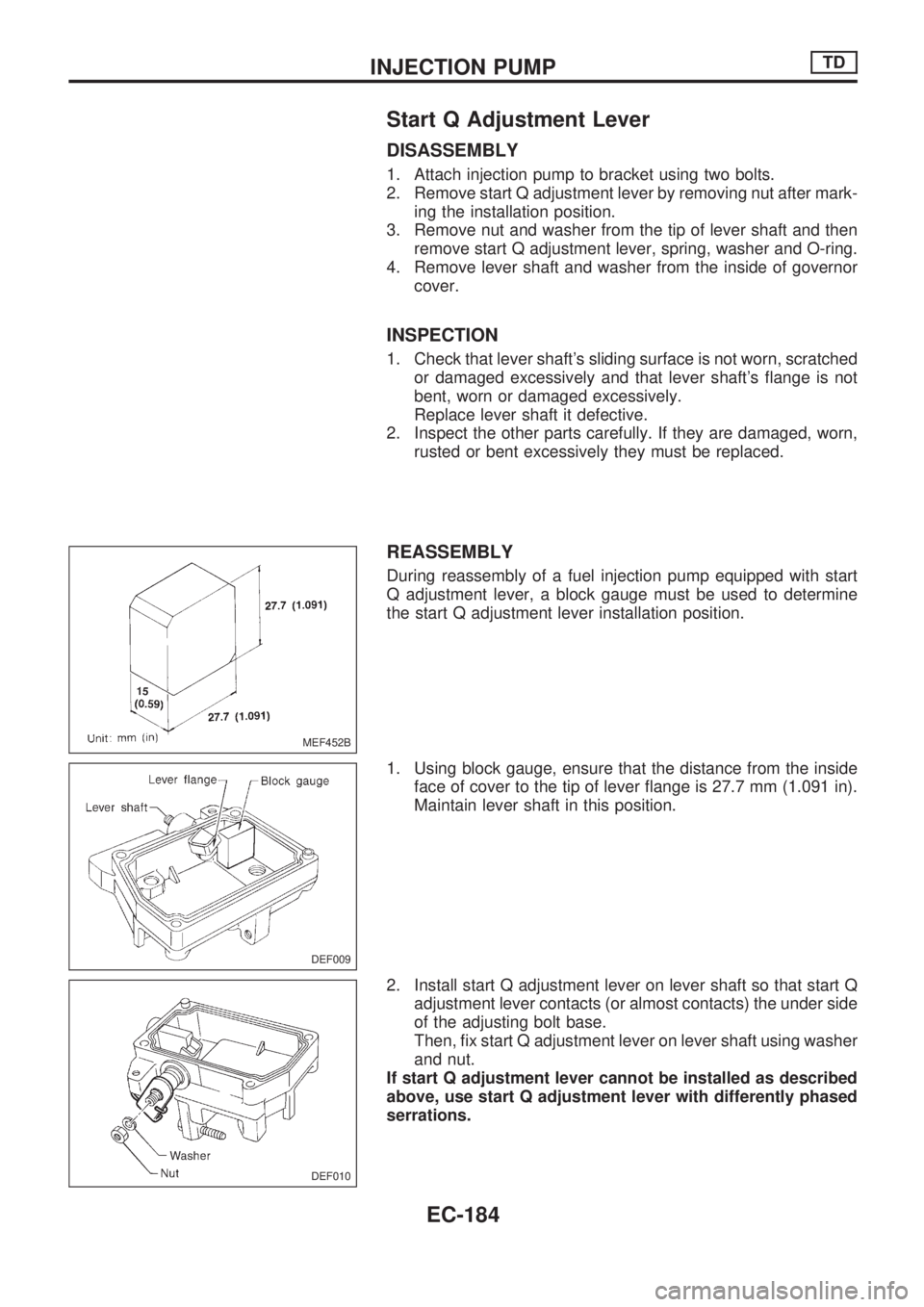
REASSEMBLY
During reassembly of a fuel injection pump equipped with start
Q adjustment lever, a block gauge must be used to determine
the start Q adjustment lever installation position.
1. Using block gauge, ensure that the distance from the inside
face of cover to the tip of lever flange is 27.7 mm (1.091 in).
Maintain lever shaft in this position.
2. Install start Q adjustment lever on lever shaft so that start Q
adjustment lever contacts (or almost contacts) the under side
of the adjusting bolt base.
Then, fix start Q adjustment lever on lever shaft using washer
and nut.
If start Q adjustment lever cannot be installed as described
above, use start Q adjustment lever with differently phased
serrations.
MEF452B
DEF009
DEF010
INJECTION PUMPTD
EC-184
Page 341 of 1659
Assembly
Assemble in the reverse order of disassembly.
Inlet connector to nozzle holder:
:29-49Nzm (3.0 - 5.0 kg-m, 22 - 36 ft-lb)
Test and Adjustment
WARNING:
When using nozzle tester, be careful not to allow diesel fuel
sprayed from nozzle to contact your hand or body, and
make sure your eyes are properly protected with goggles.
INJECTION PRESSURE TEST
1. Install nozzle to injection nozzle tester and bleed air from
flare nut.
2. Pump the tester handle slowly (one time per second) and
watch the pressure gauge.
3. Read the pressure gauge when the injection pressure just
starts dropping.
Initial injection pressure:
Used 9,807 - 10,297 kPa
(98.1 - 103.0 bar, 100 - 105 kg/cm
2,
1,422 - 1,493 psi)
New 10,297 - 11,278 kPa
(103.0 - 112.8 bar, 105 - 115 kg/cm
2,
1,493 - 1,635 psi)
Always check initial injection pressure using a new nozzle.
SEF967
EF791A
SEF672A
INJECTION NOZZLETD
EC-189
Page 343 of 1659

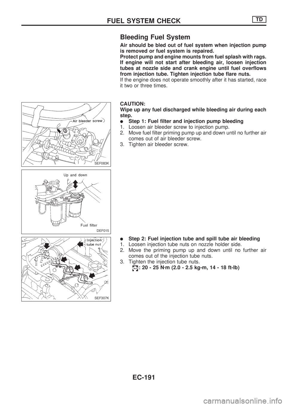
Bleeding Fuel System
Air should be bled out of fuel system when injection pump
is removed or fuel system is repaired.
Protect pump and engine mounts from fuel splash with rags.
If engine will not start after bleeding air, loosen injection
tubes at nozzle side and crank engine until fuel overflows
from injection tube. Tighten injection tube flare nuts.
If the engine does not operate smoothly after it has started, race
it two or three times.
CAUTION:
Wipe up any fuel discharged while bleeding air during each
step.
lStep 1: Fuel filter and injection pump bleeding
1. Loosen air bleeder screw to injection pump.
2. Move fuel filter priming pump up and down until no further air
comes out of air bleeder screw.
3. Tighten air bleeder screw.
lStep 2: Fuel injection tube and spill tube air bleeding
1. Loosen injection tube nuts on nozzle holder side.
2. Move the priming pump up and down until no further air
comes out of the injection tube nuts.
3. Tighten the injection tube nuts.
:20-25Nzm (2.0 - 2.5 kg-m, 14 - 18 ft-lb)
SEF083K
DEF015
SEF307K
FUEL SYSTEM CHECKTD
EC-191
Page 344 of 1659
Bleeding Fuel Filter
1. Move the priming pump up and down to bleed air from the
fuel filter.
2. When air is completely bled from the fuel pump, priming
pump operation becomes noticeably heavy. Stop pump
operation.
Checking Priming Pump
Before checking priming pump, make sure that fuel filter is
filled with fuel.
1. Disconnect fuel return hose.
Place a suitable container beneath hose end.
2. Pump priming pump and check that the fuel overflows from
the hose end. If not, replace priming pump.
Checking Fuel Filter Switch
1. Remove the connector from filter and fuel filter switch.
2. Turn the key switch ``ON''. Lift the float to ensure that the
warning lamp turns on.
Fuel filter switch tightening torque:
: 3.9 - 5.9 Nzm (0.4 - 0.6 kg-m, 35 - 52 in-lb)
Discard the old O-ring and replace it with a new one.
DEF017
SEF122U
FUEL SYSTEM CHECKTD
EC-192
Page 372 of 1659
Description
To improve startability, a solenoid timer is used on models for
cold areas. Its purpose is to advance fuel injection timing in
relation to coolant temperature for a certain period after starting
the engine.
This timer is controlled by the signal from the glow control unit
(or ECM). The control unit sends a signal to activate the advance
mechanism of the fuel injection pump during cold starting.
Refer to ``Circuit Diagram'', ``QUICK-GLOW SYSTEM'', EC-195.
Operation
Part of the fuel in the return line returns to the fuel injection pump
inlet, when the solenoid timer is OFF. When cold starting, the
solenoid timer comes ON to stop the return of fuel to the inlet.
This increases the fuel pressure in the fuel injection pump so that
fuel injection timing advances. The duration of fuel injection tim-
ing advance varies with changes in coolant temperature.
SEF419FB
SEF914H
SOLENOID TIMERTD
EC-220
Page 373 of 1659

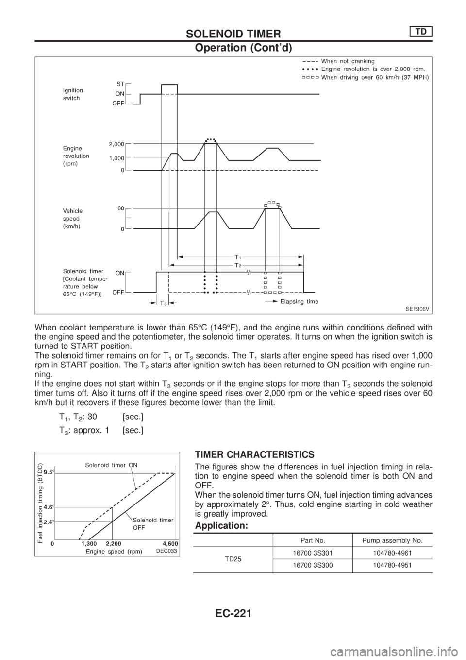
When coolant temperature is lower than 65ÉC (149ÉF), and the engine runs within conditions defined with
the engine speed and the potentiometer, the solenoid timer operates. It turns on when the ignition switch is
turned to START position.
The solenoid timer remains on for T
1or T2seconds. The T1starts after engine speed has rised over 1,000
rpm in START position. The T
2starts after ignition switch has been returned to ON position with engine run-
ning.
If the engine does not start within T
3seconds or if the engine stops for more than T3seconds the solenoid
timer turns off. Also it turns off if the engine speed rises over 2,000 rpm or the vehicle speed rises over 60
km/h but it recovers if these figures become lower than the limit.
T1,T2: 30 [sec.]
T
3: approx. 1 [sec.]
TIMER CHARACTERISTICS
The figures show the differences in fuel injection timing in rela-
tion to engine speed when the solenoid timer is both ON and
OFF.
When the solenoid timer turns ON, fuel injection timing advances
by approximately 2É. Thus, cold engine starting in cold weather
is greatly improved.
Application:
Part No. Pump assembly No.
TD2516700 3S301 104780-4961
16700 3S300 104780-4951
SEF906V
DEC033
.
SOLENOID TIMERTD
Operation (Cont'd)
EC-221
Page 376 of 1659
Inspection
SOLENOID TIMER CONTROL CIRCUIT
1. Connect test lamp to glow control unit as shown.
2. Disconnect the harness connector from starter motor ``S''
terminal.
3. Make sure that test lamp comes on when ignition switch is
turned to START.
4. Measure the time the test lamp stays lit when ignition switch
is turned to ON from START.
Time the test lamp should stay lit:
Approx. 30 seconds at coolant temperature below
65ÉC (149ÉF)
0 seconds at coolant temperature over 65ÉC
(149ÉF)
SOLENOID TIMER
1. Disconnect solenoid timer harness and check for ``clicking''
sound from solenoid when battery is connected and discon-
nected.
If solenoid has malfunction, replace it.
After checking, reconnect the connector.
TIMER PISTON STROKE (Using pump tester)
Measure timer piston strokes at specified fuel injection pump
speed when solenoid timer is on and off.
Refer to ``Injection Pump Calibration Standard'' in SDS.
DEC034
.
SEF907V
SOLENOID TIMERTD
EC-224