1998 NISSAN PICK-UP coolant
[x] Cancel search: coolantPage 202 of 1659
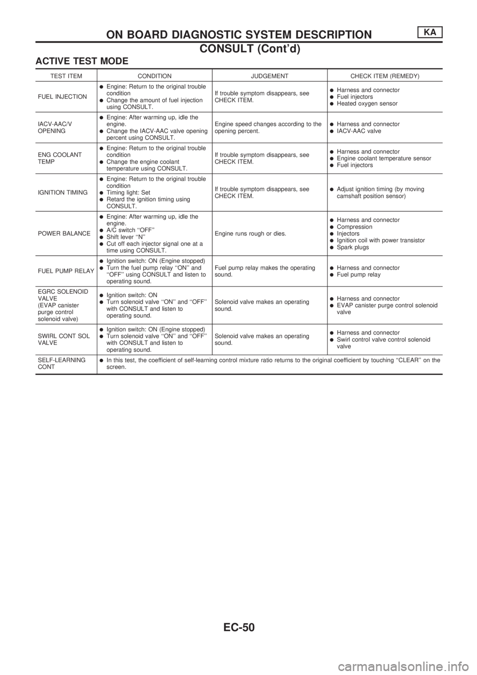
ACTIVE TEST MODE
TEST ITEM CONDITION JUDGEMENT CHECK ITEM (REMEDY)
FUEL INJECTION
lEngine: Return to the original trouble
condition
lChange the amount of fuel injection
using CONSULT.If trouble symptom disappears, see
CHECK ITEM.
lHarness and connectorlFuel injectorslHeated oxygen sensor
IACV-AAC/V
OPENING
lEngine: After warming up, idle the
engine.
lChange the IACV-AAC valve opening
percent using CONSULT.Engine speed changes according to the
opening percent.lHarness and connectorlIACV-AAC valve
ENG COOLANT
TEMP
lEngine: Return to the original trouble
condition
lChange the engine coolant
temperature using CONSULT.If trouble symptom disappears, see
CHECK ITEM.
lHarness and connectorlEngine coolant temperature sensorlFuel injectors
IGNITION TIMING
lEngine: Return to the original trouble
condition
lTiming light: SetlRetard the ignition timing using
CONSULT.If trouble symptom disappears, see
CHECK ITEM.
lAdjust ignition timing (by moving
camshaft position sensor)
POWER BALANCE
lEngine: After warming up, idle the
engine.
lA/C switch ``OFF''lShift lever ``N''lCut off each injector signal one at a
time using CONSULT.Engine runs rough or dies.
lHarness and connectorlCompressionlInjectorslIgnition coil with power transistorlSpark plugs
FUEL PUMP RELAY
lIgnition switch: ON (Engine stopped)lTurn the fuel pump relay ``ON'' and
``OFF'' using CONSULT and listen to
operating sound.Fuel pump relay makes the operating
sound.lHarness and connectorlFuel pump relay
EGRC SOLENOID
VALVE
(EVAP canister
purge control
solenoid valve)
lIgnition switch: ONlTurn solenoid valve ``ON'' and ``OFF''
with CONSULT and listen to
operating sound.Solenoid valve makes an operating
sound.lHarness and connectorlEVAP canister purge control solenoid
valve
SWIRL CONT SOL
VALVE
lIgnition switch: ON (Engine stopped)lTurn solenoid valve ``ON'' and ``OFF''
with CONSULT and listen to
operating sound.Solenoid valve makes an operating
sound.lHarness and connectorlSwirl control valve control solenoid
valve
SELF-LEARNING
CONT
lIn this test, the coefficient of self-learning control mixture ratio returns to the original coefficient by touching ``CLEAR'' on the
screen.
ON BOARD DIAGNOSTIC SYSTEM DESCRIPTIONKA
CONSULT (Cont'd)
EC-50
Page 213 of 1659
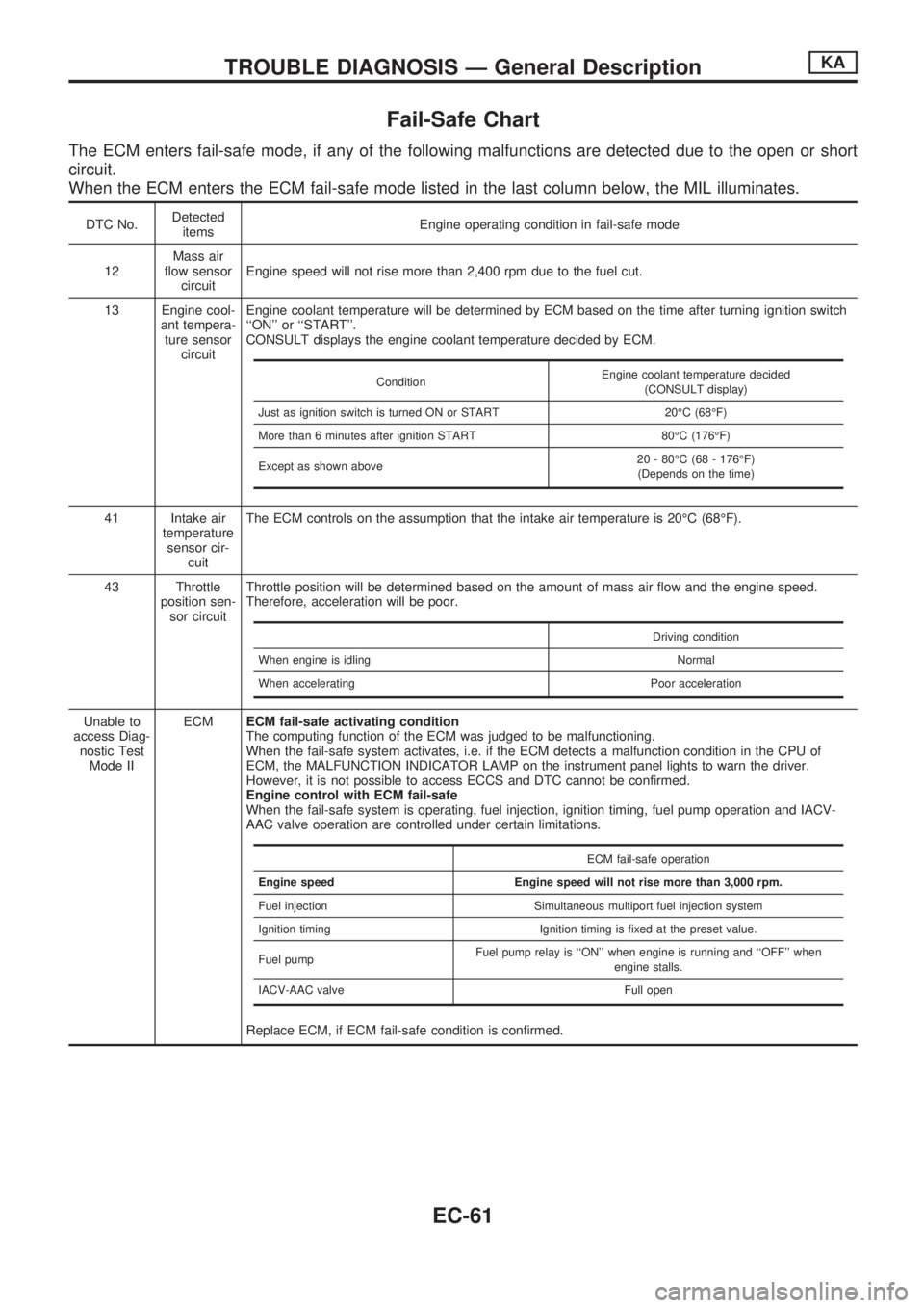
Fail-Safe Chart
The ECM enters fail-safe mode, if any of the following malfunctions are detected due to the open or short
circuit.
When the ECM enters the ECM fail-safe mode listed in the last column below, the MIL illuminates.
DTC No.Detected
itemsEngine operating condition in fail-safe mode
12Mass air
flow sensor
circuitEngine speed will not rise more than 2,400 rpm due to the fuel cut.
13 Engine cool-
ant tempera-
ture sensor
circuitEngine coolant temperature will be determined by ECM based on the time after turning ignition switch
``ON'' or ``START''.
CONSULT displays the engine coolant temperature decided by ECM.
41 Intake air
temperature
sensor cir-
cuitThe ECM controls on the assumption that the intake air temperature is 20ÉC (68ÉF).
43 Throttle
position sen-
sor circuitThrottle position will be determined based on the amount of mass air flow and the engine speed.
Therefore, acceleration will be poor.
Unable to
access Diag-
nostic Test
Mode IIECMECM fail-safe activating condition
The computing function of the ECM was judged to be malfunctioning.
When the fail-safe system activates, i.e. if the ECM detects a malfunction condition in the CPU of
ECM, the MALFUNCTION INDICATOR LAMP on the instrument panel lights to warn the driver.
However, it is not possible to access ECCS and DTC cannot be confirmed.
Engine control with ECM fail-safe
When the fail-safe system is operating, fuel injection, ignition timing, fuel pump operation and IACV-
AAC valve operation are controlled under certain limitations.
Replace ECM, if ECM fail-safe condition is confirmed.
ConditionEngine coolant temperature decided
(CONSULT display)
Just as ignition switch is turned ON or START 20ÉC (68ÉF)
More than 6 minutes after ignition START 80ÉC (176ÉF)
Except as shown above20 - 80ÉC (68 - 176ÉF)
(Depends on the time)
Driving condition
When engine is idling Normal
When accelerating Poor acceleration
ECM fail-safe operation
Engine speed Engine speed will not rise more than 3,000 rpm.
Fuel injection Simultaneous multiport fuel injection system
Ignition timing Ignition timing is fixed at the preset value.
Fuel pumpFuel pump relay is ``ON'' when engine is running and ``OFF'' when
engine stalls.
IACV-AAC valve Full open
TROUBLE DIAGNOSIS Ð General DescriptionKA
EC-61
Page 214 of 1659

Symptom Matrix Chart
SYMPTOM
Reference page
HARD/NO START/RESTART (EXCP. HA)
ENGINE STALL
HESITATION/SURGING/FLAT SPOT
SPARK KNOCK/DETONATION
LACK OF POWER/POOR ACCELERATION
HIGH IDLE/LOW IDLE
ROUGH IDLE/HUNTING
IDLING VIBRATION
SLOW/NO RETURN TO IDLE
OVERHEATS/WATER TEMPERATURE HIGH
EXCESSIVE FUEL CONSUMPTION
EXCESSIVE OIL CONSUMPTION
BATTERY DEAD (UNDER CHARGE)
OVERCOOLS
OVERCHARGING
Warranty Symptom Code AA AB AC AD AE AF AG AH AJ AK AL AM HA 1P 1X
Basic engine control system
Fuel Fuel pump circuitllljlljjjEC-151
Fuel pressure regulator system
llljljlljlEC-22
Injector circuit
llljlll lEC-144
Evaporative emission systemjjjj
ljjjj jEC-19
Air Positive crankcase ventilation systemjjjj
ljjjj jjEC-21
Incorrect idle speed adjustmentjj jjjj jEC-25
Swirl control valve circuitjj
lEC-161
IACV-AAC valve circuit
llljllllljjEC-131
IACV-FICD solenoid valve circuitjjjjjjjjj jEC-168
Ignition Incorrect ignition timing adjustmentjj
lll ll lEC-25
Ignition circuit
lllll ll lEC-99
EVAP EVAP canister purge control solenoid
valve circuit
ljjjj j jEC-140
Main power supply and ground circuit
llljj jj jj jEC-75
Air conditioner circuitjjjjjjjjj j jHA section
ECCS system
ECCS Camshaft position sensor circuitllllljj jEC-82
Mass air flow sensor circuit
lllll ljjEC-89
Heated oxygen sensor circuit
lljlljlEC-123, 127
Engine coolant temperature sensor circuit
llljllljjlEC-95
Throttle position sensor circuit
ll lllll lEC-113
Incorrect throttle position sensor adjust-
ment
ljjljjljEC-58
Vehicle speed sensor circuitjj j jEC-118
ECMjjjjjjjjjjjEC-61
Start signal circuitjEC-149
Neutral position switch circuitjjjj jEC-136
Power steering oil pressure switch circuitjjjEC-157
l; High Possibility Item
j; Low Possibility Item(continued on next page)
TROUBLE DIAGNOSIS Ð General DescriptionKA
EC-62
Page 215 of 1659
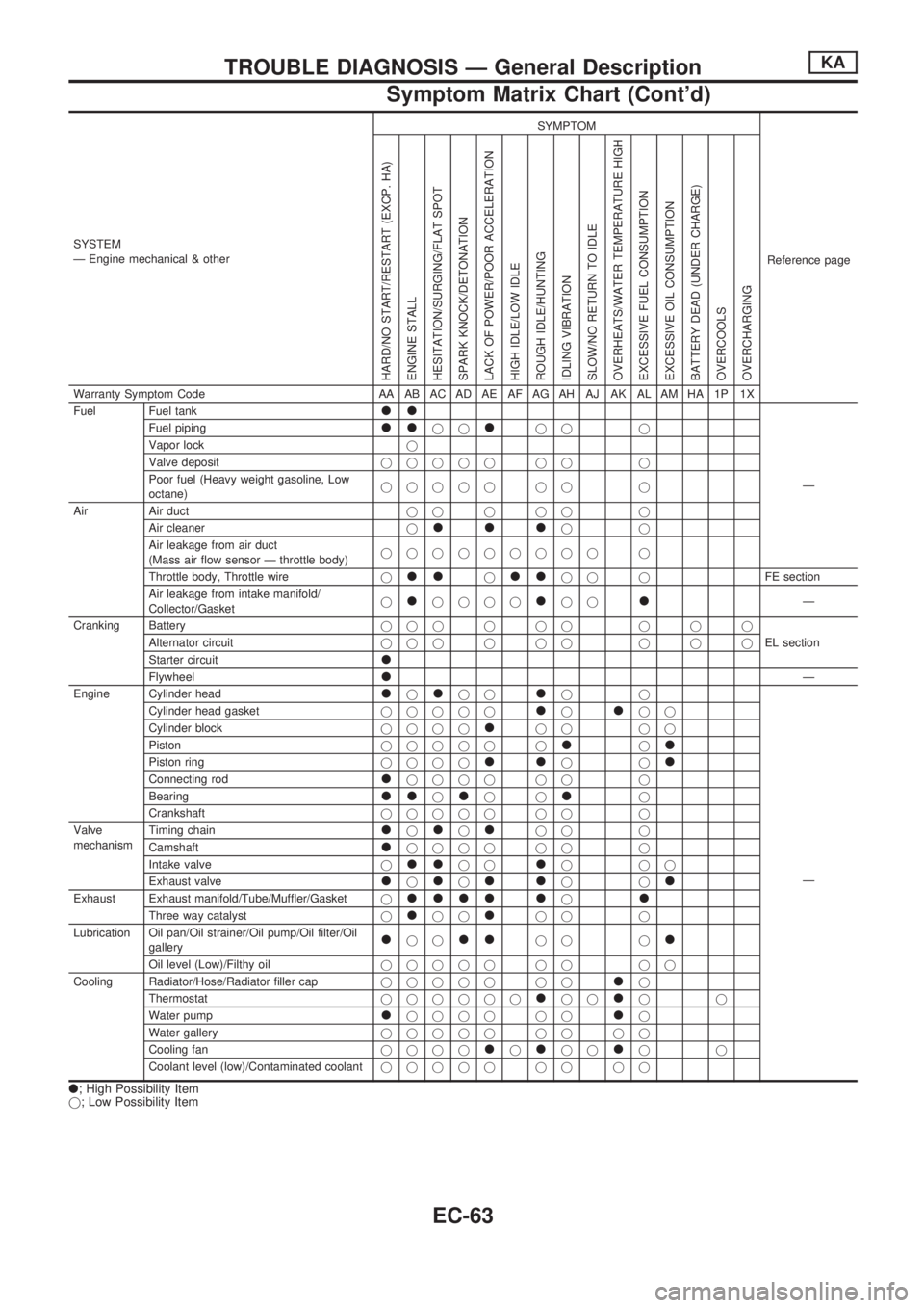
SYSTEM
Ð Engine mechanical & otherSYMPTOM
Reference page
HARD/NO START/RESTART (EXCP. HA)
ENGINE STALL
HESITATION/SURGING/FLAT SPOT
SPARK KNOCK/DETONATION
LACK OF POWER/POOR ACCELERATION
HIGH IDLE/LOW IDLE
ROUGH IDLE/HUNTING
IDLING VIBRATION
SLOW/NO RETURN TO IDLE
OVERHEATS/WATER TEMPERATURE HIGH
EXCESSIVE FUEL CONSUMPTION
EXCESSIVE OIL CONSUMPTION
BATTERY DEAD (UNDER CHARGE)
OVERCOOLS
OVERCHARGING
Warranty Symptom Code AA AB AC AD AE AF AG AH AJ AK AL AM HA 1P 1X
Fuel Fuel tank
ll
Ð Fuel piping
lljjljj j
Vapor lockj
Valve depositjjjjj jj j
Poor fuel (Heavy weight gasoline, Low
octane)jjjjj jj j
Air Air ductjjjjj j
Air cleanerj
llljj
Air leakage from air duct
(Mass air flow sensor Ð throttle body)jjjjjjjjj j
Throttle body, Throttle wirej
lljlljj jFE section
Air leakage from intake manifold/
Collector/Gasketj
ljjjjljjlÐ
Cranking Batteryjjjjjj jjj
EL section Alternator circuitjjjjjj jjj
Starter circuit
l
FlywheellÐ
Engine Cylinder head
ljljjljj
Ð Cylinder head gasketjjjjj
ljljj
Cylinder blockjjjj
ljj jj
Pistonjjjjj j
ljl
Piston ringjjjjlljjl
Connecting rodljjjj jj j
Bearing
lljljjlj
Crankshaftjjjjj jj j
Valve
mechanismTiming chain
ljljljj j
Camshaft
ljjjj jj j
Intake valvej
lljjljjj
Exhaust valve
ljljlljjl
Exhaust Exhaust manifold/Tube/Muffler/Gasketjllll ljl
Three way catalystjljjljj j
Lubrication Oil pan/Oil strainer/Oil pump/Oil filter/Oil
gallery
ljjlljj jl
Oil level (Low)/Filthy oiljjjjj jj jj
Cooling Radiator/Hose/Radiator filler capjjjjj jj
lj
Thermostatjjjjjj
ljjljj
Water pump
ljjjj jjlj
Water galleryjjjjj jj jj
Cooling fanjjjj
ljljjljj
Coolant level (low)/Contaminated coolantjjjjj jj jj
l; High Possibility Item
j; Low Possibility Item
TROUBLE DIAGNOSIS Ð General DescriptionKA
Symptom Matrix Chart (Cont'd)
EC-63
Page 222 of 1659
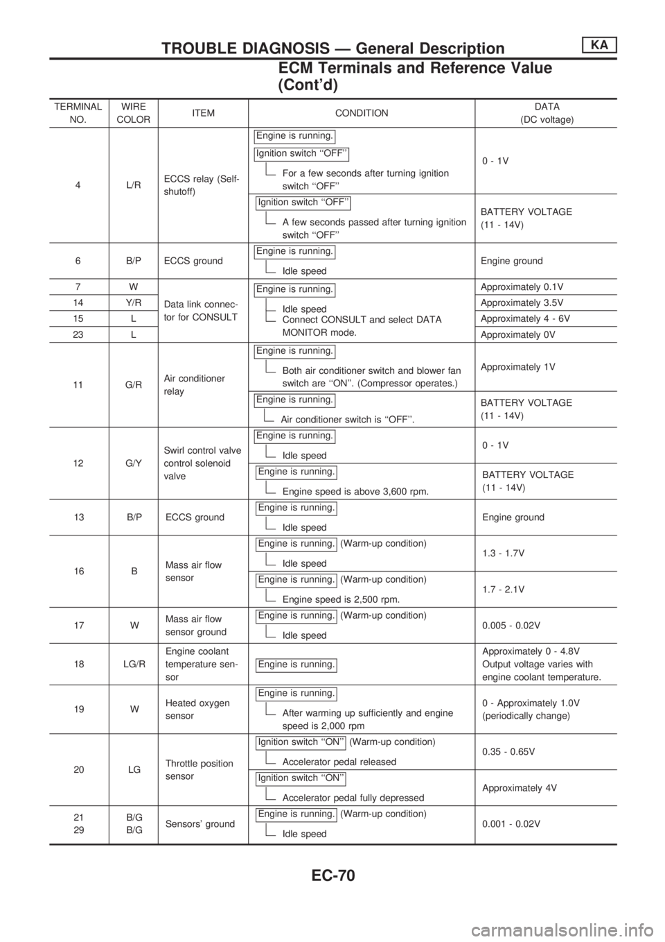
TERMINAL
NO.WIRE
COLORITEM CONDITIONDATA
(DC voltage)
4 L/RECCS relay (Self-
shutoff)Engine is running.
Ignition switch ``OFF''
For a few seconds after turning ignition
switch ``OFF''0-1V
Ignition switch ``OFF''
A few seconds passed after turning ignition
switch ``OFF''BATTERY VOLTAGE
(11 - 14V)
6 B/P ECCS groundEngine is running.
Idle speedEngine ground
7W
Data link connec-
tor for CONSULTEngine is running.
Idle speedConnect CONSULT and select DATA
MONITOR mode.Approximately 0.1V
14 Y/RApproximately 3.5V
15 LApproximately4-6V
23 LApproximately 0V
11 G/RAir conditioner
relayEngine is running.
Both air conditioner switch and blower fan
switch are ``ON''. (Compressor operates.)Approximately 1V
Engine is running.
Air conditioner switch is ``OFF''.BATTERY VOLTAGE
(11 - 14V)
12 G/YSwirl control valve
control solenoid
valveEngine is running.
Idle speed0-1V
Engine is running.
Engine speed is above 3,600 rpm.BATTERY VOLTAGE
(11 - 14V)
13 B/P ECCS groundEngine is running.
Idle speedEngine ground
16 BMass air flow
sensorEngine is running.
(Warm-up condition)
Idle speed1.3 - 1.7V
Engine is running.
(Warm-up condition)
Engine speed is 2,500 rpm.1.7 - 2.1V
17 WMass air flow
sensor groundEngine is running.
(Warm-up condition)
Idle speed0.005 - 0.02V
18 LG/REngine coolant
temperature sen-
sorEngine is running.
Approximately 0 - 4.8V
Output voltage varies with
engine coolant temperature.
19 WHeated oxygen
sensorEngine is running.
After warming up sufficiently and engine
speed is 2,000 rpm0 - Approximately 1.0V
(periodically change)
20 LGThrottle position
sensorIgnition switch ``ON''
(Warm-up condition)
Accelerator pedal released0.35 - 0.65V
Ignition switch ``ON''
Accelerator pedal fully depressedApproximately 4V
21
29B/G
B/GSensors' groundEngine is running.
(Warm-up condition)
Idle speed0.001 - 0.02V
TROUBLE DIAGNOSIS Ð General DescriptionKA
ECM Terminals and Reference Value
(Cont'd)
EC-70
Page 247 of 1659
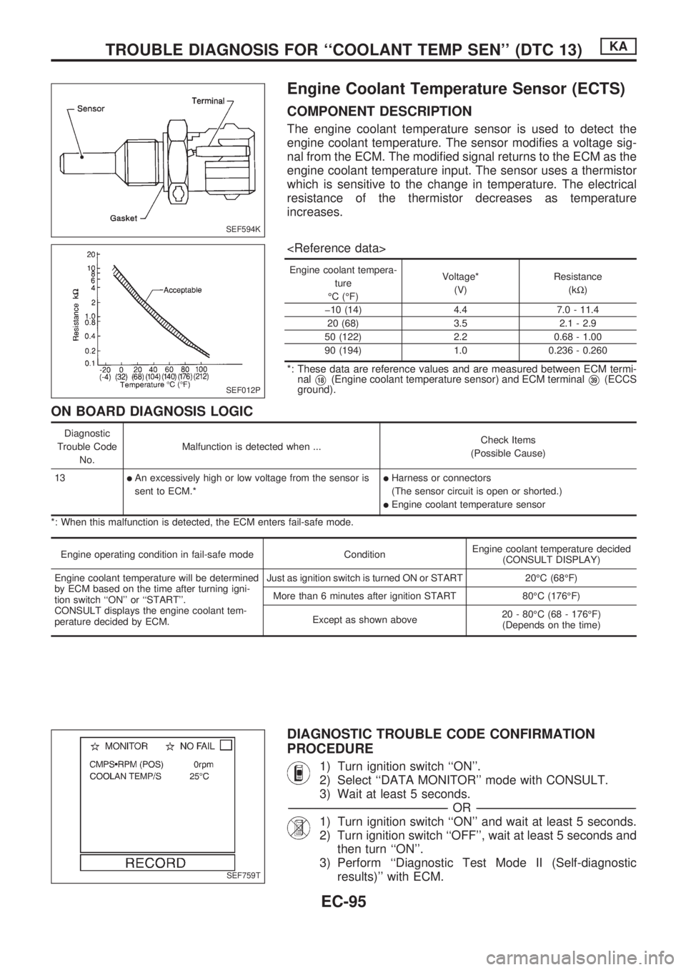
Engine Coolant Temperature Sensor (ECTS)
COMPONENT DESCRIPTION
The engine coolant temperature sensor is used to detect the
engine coolant temperature. The sensor modifies a voltage sig-
nal from the ECM. The modified signal returns to the ECM as the
engine coolant temperature input. The sensor uses a thermistor
which is sensitive to the change in temperature. The electrical
resistance of the thermistor decreases as temperature
increases.
Engine coolant tempera-
ture
ÉC (ÉF)Voltage*
(V)Resistance
(kW)
þ10 (14) 4.4 7.0 - 11.4
20 (68) 3.5 2.1 - 2.9
50 (122) 2.2 0.68 - 1.00
90 (194) 1.0 0.236 - 0.260
*: These data are reference values and are measured between ECM termi-
nal
V18(Engine coolant temperature sensor) and ECM terminalV39(ECCS
ground).
ON BOARD DIAGNOSIS LOGIC
Diagnostic
Trouble Code
No.Malfunction is detected when ...Check Items
(Possible Cause)
13
lAn excessively high or low voltage from the sensor is
sent to ECM.*lHarness or connectors
(The sensor circuit is open or shorted.)
lEngine coolant temperature sensor
*: When this malfunction is detected, the ECM enters fail-safe mode.
Engine operating condition in fail-safe mode ConditionEngine coolant temperature decided
(CONSULT DISPLAY)
Engine coolant temperature will be determined
by ECM based on the time after turning igni-
tion switch ``ON'' or ``START''.
CONSULT displays the engine coolant tem-
perature decided by ECM.Just as ignition switch is turned ON or START 20ÉC (68ÉF)
More than 6 minutes after ignition START 80ÉC (176ÉF)
Except as shown above20 - 80ÉC (68 - 176ÉF)
(Depends on the time)
DIAGNOSTIC TROUBLE CODE CONFIRMATION
PROCEDURE
1) Turn ignition switch ``ON''.
2) Select ``DATA MONITOR'' mode with CONSULT.
3) Wait at least 5 seconds.
-------------------------------------------------------------------------------------------------------------------------------------------------------------------------------------------------------------------------------------------------OR-------------------------------------------------------------------------------------------------------------------------------------------------------------------------------------------------------------------------------------------------
1) Turn ignition switch ``ON'' and wait at least 5 seconds.
2) Turn ignition switch ``OFF'', wait at least 5 seconds and
then turn ``ON''.
3) Perform ``Diagnostic Test Mode II (Self-diagnostic
results)'' with ECM.
SEF594K
SEF012P
SEF759T
TROUBLE DIAGNOSIS FOR ``COOLANT TEMP SEN'' (DTC 13)KA
EC-95
Page 248 of 1659
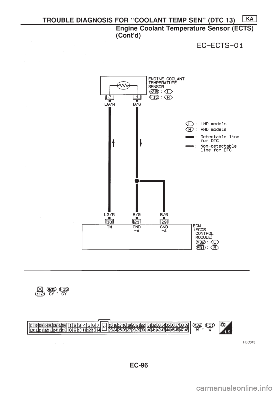
HEC343
TROUBLE DIAGNOSIS FOR ``COOLANT TEMP SEN'' (DTC 13)KA
Engine Coolant Temperature Sensor (ECTS)
(Cont'd)
EC-96
Page 249 of 1659
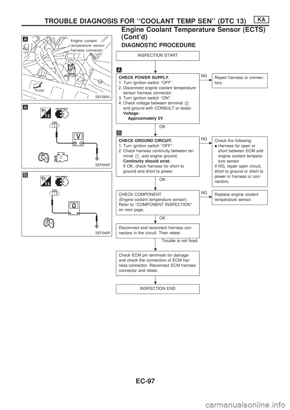
DIAGNOSTIC PROCEDURE
INSPECTION START
CHECK POWER SUPPLY.
1. Turn ignition switch ``OFF''.
2. Disconnect engine coolant temperature
sensor harness connector.
3. Turn ignition switch ``ON''.
4. Check voltage between terminal
V2
and ground with CONSULT or tester.
Voltage:
Approximately 5V
OK
cNG
Repair harness or connec-
tors.
CHECK GROUND CIRCUIT.
1. Turn ignition switch ``OFF''.
2. Check harness continuity between ter-
minal
V1and engine ground.
Continuity should exist.
If OK, check harness for short to
ground and short to power.
OK
cNG
Check the following.
lHarness for open or
short between ECM and
engine coolant tempera-
ture sensor
If NG, repair open circuit,
short to ground or short to
power in harness or con-
nectors.
CHECK COMPONENT
(Engine coolant temperature sensor).
Refer to ``COMPONENT INSPECTION''
on next page.
OK
cNG
Replace engine coolant
temperature sensor.
Disconnect and reconnect harness con-
nectors in the circuit. Then retest.
Trouble is not fixed.
Check ECM pin terminals for damage
and check the connection of ECM har-
ness connector. Reconnect ECM harness
connector and retest.
INSPECTION END
SEF083U
SEF645R
SEF646R
.
.
.
.
.
.
TROUBLE DIAGNOSIS FOR ``COOLANT TEMP SEN'' (DTC 13)KA
Engine Coolant Temperature Sensor (ECTS)
(Cont'd)
EC-97