Page 643 of 1659
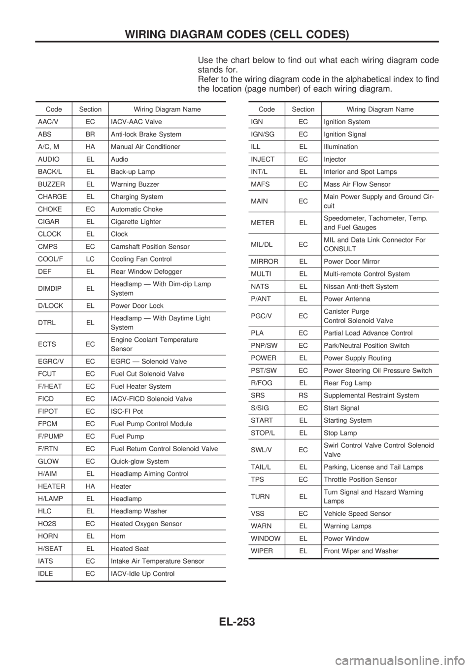
Use the chart below to find out what each wiring diagram code
stands for.
Refer to the wiring diagram code in the alphabetical index to find
the location (page number) of each wiring diagram.
Code Section Wiring Diagram Name
AAC/V EC IACV-AAC Valve
ABS BR Anti-lock Brake System
A/C, M HA Manual Air Conditioner
AUDIO EL Audio
BACK/L EL Back-up Lamp
BUZZER EL Warning Buzzer
CHARGE EL Charging System
CHOKE EC Automatic Choke
CIGAR EL Cigarette Lighter
CLOCK EL Clock
CMPS EC Camshaft Position Sensor
COOL/F LC Cooling Fan Control
DEF EL Rear Window Defogger
DIMDIP ELHeadlamp Ð With Dim-dip Lamp
System
D/LOCK EL Power Door Lock
DTRL ELHeadlamp Ð With Daytime Light
System
ECTS ECEngine Coolant Temperature
Sensor
EGRC/V EC EGRC Ð Solenoid Valve
FCUT EC Fuel Cut Solenoid Valve
F/HEAT EC Fuel Heater System
FICD EC IACV-FICD Solenoid Valve
FIPOT EC ISC-FI Pot
FPCM EC Fuel Pump Control Module
F/PUMP EC Fuel Pump
F/RTN EC Fuel Return Control Solenoid Valve
GLOW EC Quick-glow System
H/AIM EL Headlamp Aiming Control
HEATER HA Heater
H/LAMP EL Headlamp
HLC EL Headlamp Washer
HO2S EC Heated Oxygen Sensor
HORN EL Horn
H/SEAT EL Heated Seat
IATS EC Intake Air Temperature Sensor
IDLE EC IACV-Idle Up ControlCode Section Wiring Diagram Name
IGN EC Ignition System
IGN/SG EC Ignition Signal
ILL EL Illumination
INJECT EC Injector
INT/L EL Interior and Spot Lamps
MAFS EC Mass Air Flow Sensor
MAIN ECMain Power Supply and Ground Cir-
cuit
METER ELSpeedometer, Tachometer, Temp.
and Fuel Gauges
MIL/DL ECMIL and Data Link Connector For
CONSULT
MIRROR EL Power Door Mirror
MULTI EL Multi-remote Control System
NATS EL Nissan Anti-theft System
P/ANT EL Power Antenna
PGC/V ECCanister Purge
Control Solenoid Valve
PLA EC Partial Load Advance Control
PNP/SW EC Park/Neutral Position Switch
POWER EL Power Supply Routing
PST/SW EC Power Steering Oil Pressure Switch
R/FOG EL Rear Fog Lamp
SRS RS Supplemental Restraint System
S/SIG EC Start Signal
START EL Starting System
STOP/L EL Stop Lamp
SWL/V ECSwirl Control Valve Control Solenoid
Valve
TAIL/L EL Parking, License and Tail Lamps
TPS EC Throttle Position Sensor
TURN ELTurn Signal and Hazard Warning
Lamps
VSS EC Vehicle Speed Sensor
WARN EL Warning Lamps
WINDOW EL Power Window
WIPER EL Front Wiper and Washer
WIRING DIAGRAM CODES (CELL CODES)
EL-253
Page 646 of 1659
Parts Requiring Angular Tightening
lUse an angle wrench for the final tightening of the following
engine parts:
(1) Cylinder head bolts
(2) Connecting rod cap nuts for gasoline engines
lDo not use a torque value for final tightening.
lThe torque value for these parts are for a preliminary step.
lEnsure thread and seat surfaces are clean and coated with
engine oil.
Liquid Gasket Application Procedure
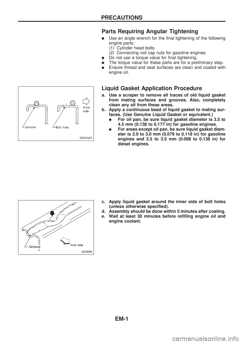
a. Use a scraper to remove all traces of old liquid gasket
from mating surfaces and grooves. Also, completely
clean any oil from these areas.
b. Apply a continuous bead of liquid gasket to mating sur-
faces. (Use Genuine Liquid Gasket or equivalent.)
lFor oil pan, be sure liquid gasket diameter is 3.5 to
4.5 mm (0.138 to 0.177 in) for gasoline engines.
lFor areas except oil pan, be sure liquid gasket diam-
eter is 2.0 to 3.0 mm (0.079 to 0.118 in) for gasoline
engines and 2.5 to 3.5 mm (0.098 to 0.138 in) for
diesel engines.
c. Apply liquid gasket around the inner side of bolt holes
(unless otherwise specified).
d. Assembly should be done within 5 minutes after coating.
e. Wait at least 30 minutes before refilling engine oil and
engine coolant.
SEM164F
AEM080
PRECAUTIONS
EM-1
Page 658 of 1659
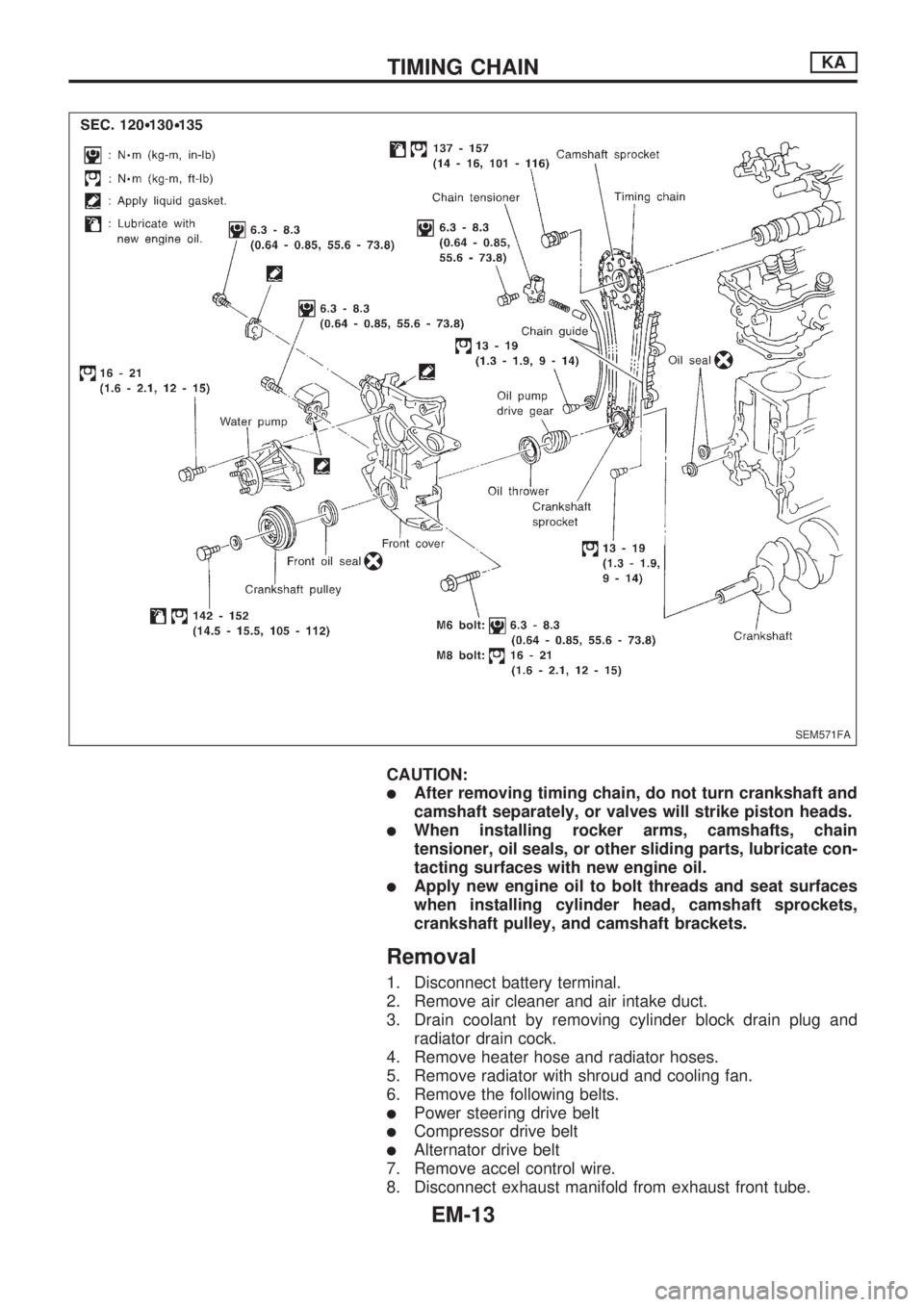
CAUTION:
lAfter removing timing chain, do not turn crankshaft and
camshaft separately, or valves will strike piston heads.
lWhen installing rocker arms, camshafts, chain
tensioner, oil seals, or other sliding parts, lubricate con-
tacting surfaces with new engine oil.
lApply new engine oil to bolt threads and seat surfaces
when installing cylinder head, camshaft sprockets,
crankshaft pulley, and camshaft brackets.
Removal
1. Disconnect battery terminal.
2. Remove air cleaner and air intake duct.
3. Drain coolant by removing cylinder block drain plug and
radiator drain cock.
4. Remove heater hose and radiator hoses.
5. Remove radiator with shroud and cooling fan.
6. Remove the following belts.
lPower steering drive belt
lCompressor drive belt
lAlternator drive belt
7. Remove accel control wire.
8. Disconnect exhaust manifold from exhaust front tube.
SEM571FA
TIMING CHAINKA
EM-13
Page 670 of 1659
CAUTION:
lWhen installing rocker arms, camshaft and oil seal, lubri-
cate contacting surfaces with new engine oil.
lWhen tightening cylinder head bolts and rocker shaft
bolts, lubricate bolt threads and seat surfaces with new
engine oil.
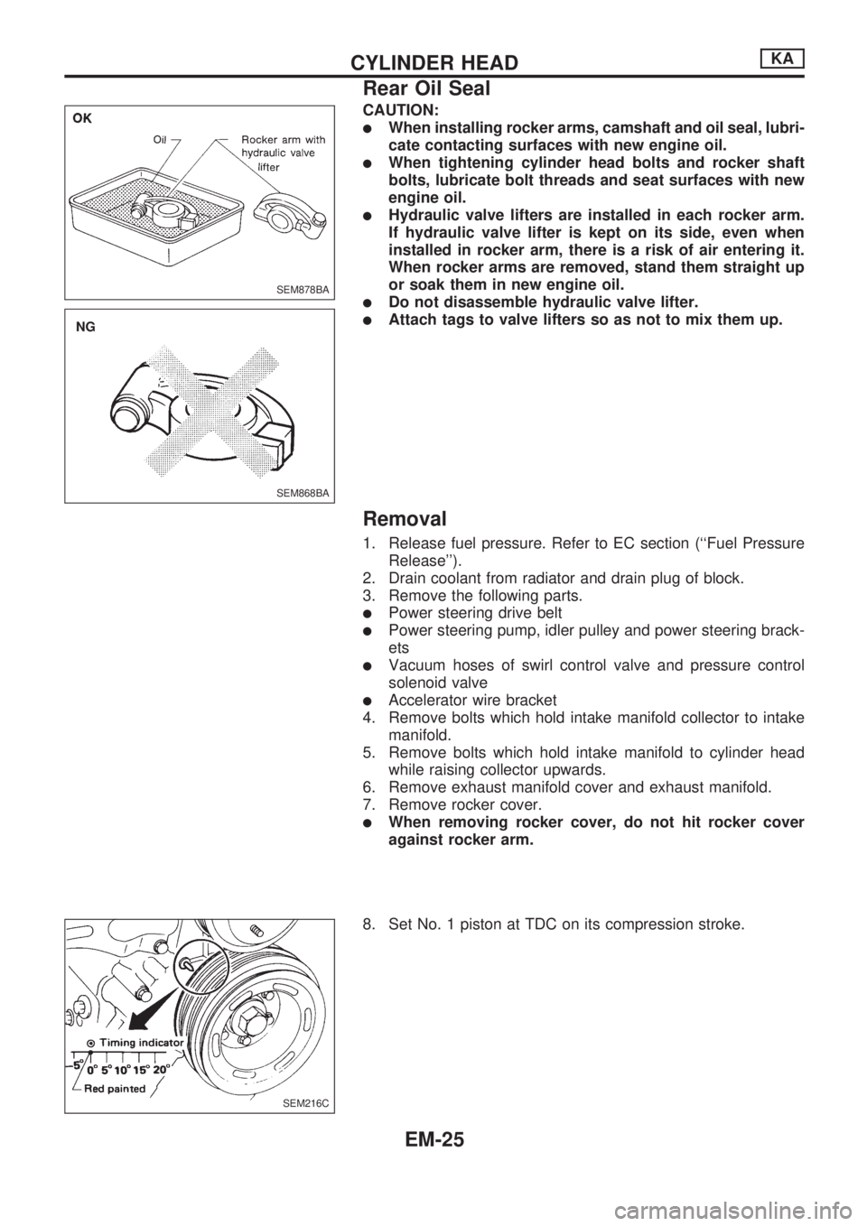
lHydraulic valve lifters are installed in each rocker arm.
If hydraulic valve lifter is kept on its side, even when
installed in rocker arm, there is a risk of air entering it.
When rocker arms are removed, stand them straight up
or soak them in new engine oil.
lDo not disassemble hydraulic valve lifter.
lAttach tags to valve lifters so as not to mix them up.
Removal
1. Release fuel pressure. Refer to EC section (``Fuel Pressure
Release'').
2. Drain coolant from radiator and drain plug of block.
3. Remove the following parts.
lPower steering drive belt
lPower steering pump, idler pulley and power steering brack-
ets
lVacuum hoses of swirl control valve and pressure control
solenoid valve
lAccelerator wire bracket
4. Remove bolts which hold intake manifold collector to intake
manifold.
5. Remove bolts which hold intake manifold to cylinder head
while raising collector upwards.
6. Remove exhaust manifold cover and exhaust manifold.
7. Remove rocker cover.
lWhen removing rocker cover, do not hit rocker cover
against rocker arm.
8. Set No. 1 piston at TDC on its compression stroke.
SEM878BA
SEM868BA
.NG
SEM216C
CYLINDER HEADKA
Rear Oil Seal
EM-25
Page 682 of 1659
Removal
1. Drain coolant from engine block and radiator. Refer to MA
section (``Changing Engine Coolant'', ``ENGINE MAINTE-
NANCE'').
2. Release fuel pressure. Refer to EC section (``Fuel Pressure
Release'').
3. Remove negative battery cable.
4. Remove hood. Refer to BT section.
5. Remove power steering drive belt, alternator drive belt and
A/C compressor drive belt.
6. Remove radiator. Refer to LC section (``Radiator'', ``ENGINE
COOLING SYSTEM'').
7. Remove exhaust manifold heat shield.
8. Disconnect exhaust system from exhaust manifold.
9. Discharge refrigerant. Refer to HA section (``R-134a Service
Procedure'', ``SERVICE PROCEDURES'').
10. Disconnect refrigerant lines. Refer to HA section (``Refriger-
ant Lines'', ``SERVICE PROCEDURES'').
11. Disconnect accelerator wire, vacuum hoses, electrical
connectors, heater hoses and vacuum booster hose.
12. Remove four power steering pump bolts.
13. Remove transmission. Refer to MT section (``Removal'',
``REMOVAL AND INSTALLATION'').
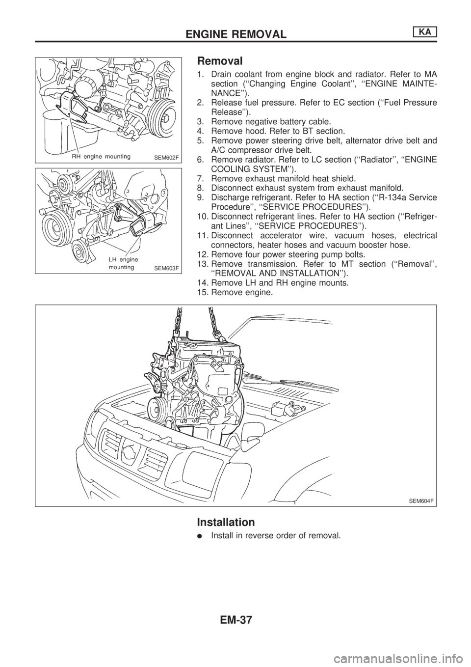
14. Remove LH and RH engine mounts.
15. Remove engine.
Installation
lInstall in reverse order of removal.
SEM602F
SEM603F
SEM604F
ENGINE REMOVALKA
EM-37
Page 684 of 1659
CAUTION:
lWhen installing sliding parts (bearings, pistons, etc.),
lubricate contacting surfaces with new engine oil.
lPlace removed parts such as bearings and bearing caps
in their proper order and direction.
lWhen installing connecting rod nuts and main bearing
cap bolts, apply new engine oil to threads and seating
surfaces.
lDo not allow any magnetic materials to contact the ring
gear teeth of flywheel or drive plate.
Disassembly
PISTON AND CRANKSHAFT
1. Remove intake manifold.
2. Place engine on a work stand.
3. Drain coolant and oil.
4. Remove oil pan.
5. Remove water pump.
6. Remove timing chain.
7. Remove cylinder head.
8. Remove pistons with connecting rod.
9. Remove bearing caps and crankshaft.
lBefore removing bearing caps, measure crankshaft end
play. Refer to EM-47.
lBolts should be loosened in two or three steps.
Inspection
PISTON AND PISTON PIN CLEARANCE
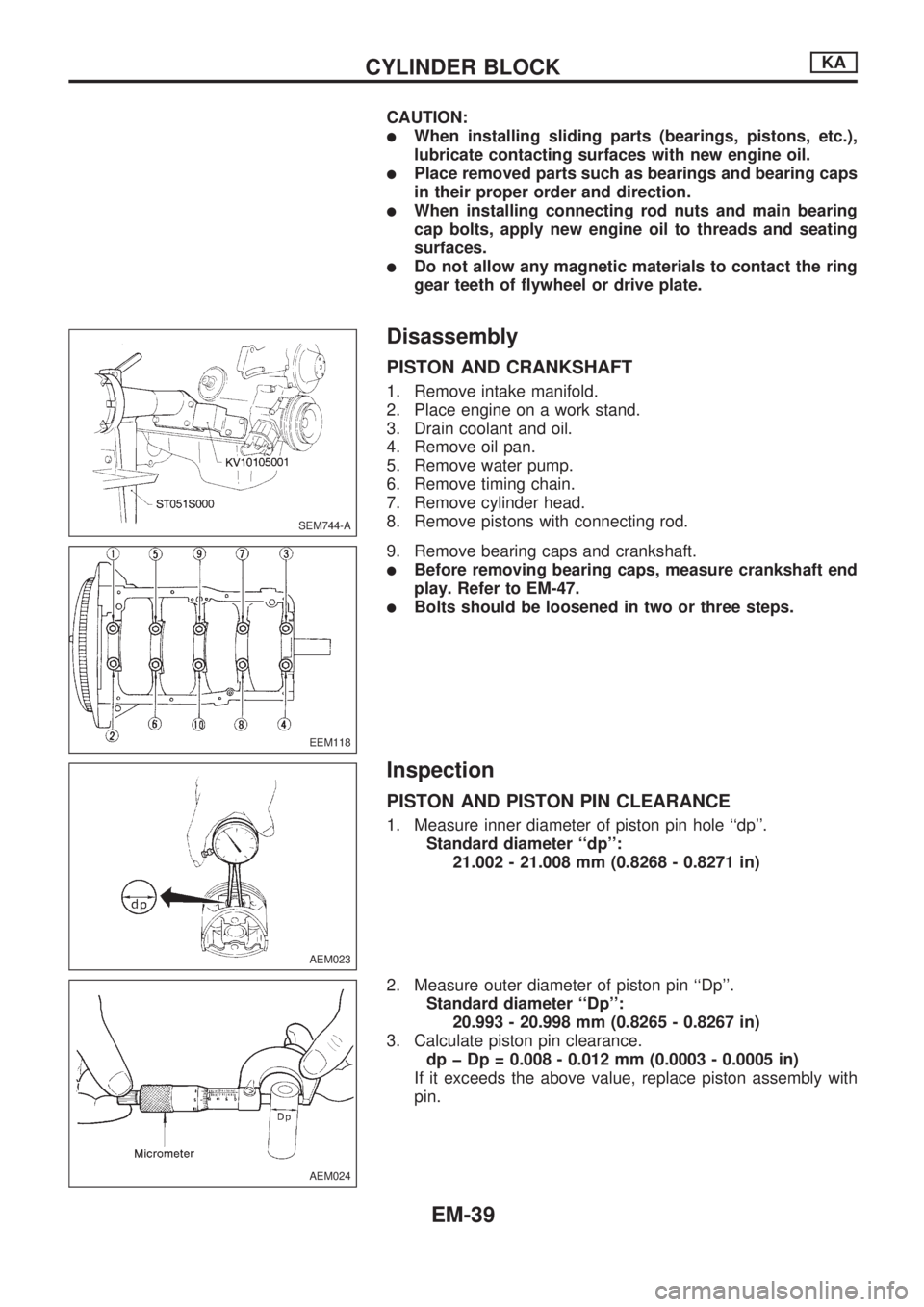
1. Measure inner diameter of piston pin hole ``dp''.
Standard diameter ``dp'':
21.002 - 21.008 mm (0.8268 - 0.8271 in)
2. Measure outer diameter of piston pin ``Dp''.
Standard diameter ``Dp'':
20.993 - 20.998 mm (0.8265 - 0.8267 in)
3. Calculate piston pin clearance.
dp þ Dp = 0.008 - 0.012 mm (0.0003 - 0.0005 in)
If it exceeds the above value, replace piston assembly with
pin.
SEM744-A
EEM118
AEM023
AEM024
CYLINDER BLOCKKA
EM-39
Page 699 of 1659
CAUTION:
lWhen installing sliding parts such as rocker arms, cam-
shaft and oil seal, be sure to apply new engine oil on
their sliding surfaces.
lWhen tightening cylinder head bolts and rocker shaft
bolts, apply new engine oil to thread portions and seat
surfaces of bolts.
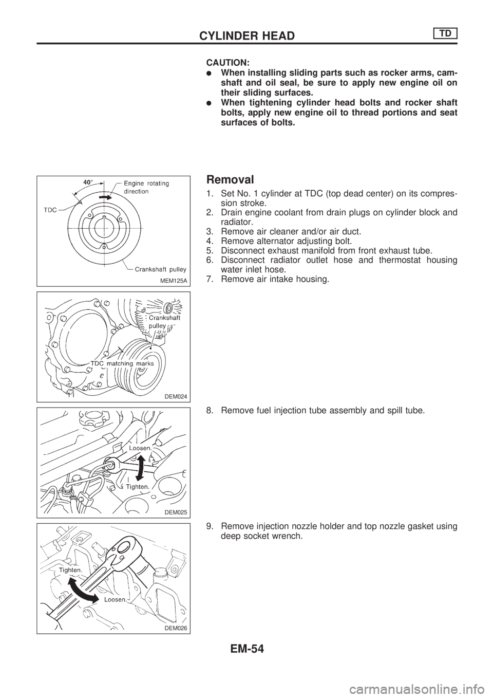
Removal
1. Set No. 1 cylinder at TDC (top dead center) on its compres-
sion stroke.
2. Drain engine coolant from drain plugs on cylinder block and
radiator.
3. Remove air cleaner and/or air duct.
4. Remove alternator adjusting bolt.
5. Disconnect exhaust manifold from front exhaust tube.
6. Disconnect radiator outlet hose and thermostat housing
water inlet hose.
7. Remove air intake housing.
8. Remove fuel injection tube assembly and spill tube.
9. Remove injection nozzle holder and top nozzle gasket using
deep socket wrench.
MEM125A
DEM024
DEM025
DEM026
CYLINDER HEADTD
EM-54
Page 711 of 1659
10. Connect thermostat housing water inlet hose and radiator
hose.
11. After assembling all disassembled parts, fill radiator and
engine with new coolant up to filler opening.
CYLINDER HEADTD
Installation (Cont'd)
EM-66