1998 NISSAN PICK-UP wiring diagram
[x] Cancel search: wiring diagramPage 54 of 1659
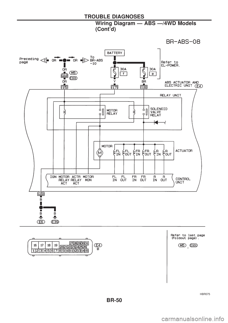
HBR075
TROUBLE DIAGNOSES
Wiring Diagram Ð ABS Ð/4WD Models
(Cont'd)
BR-50
Page 55 of 1659
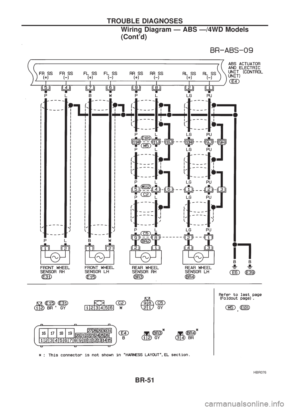
HBR076
TROUBLE DIAGNOSES
Wiring Diagram Ð ABS Ð/4WD Models
(Cont'd)
BR-51
Page 56 of 1659
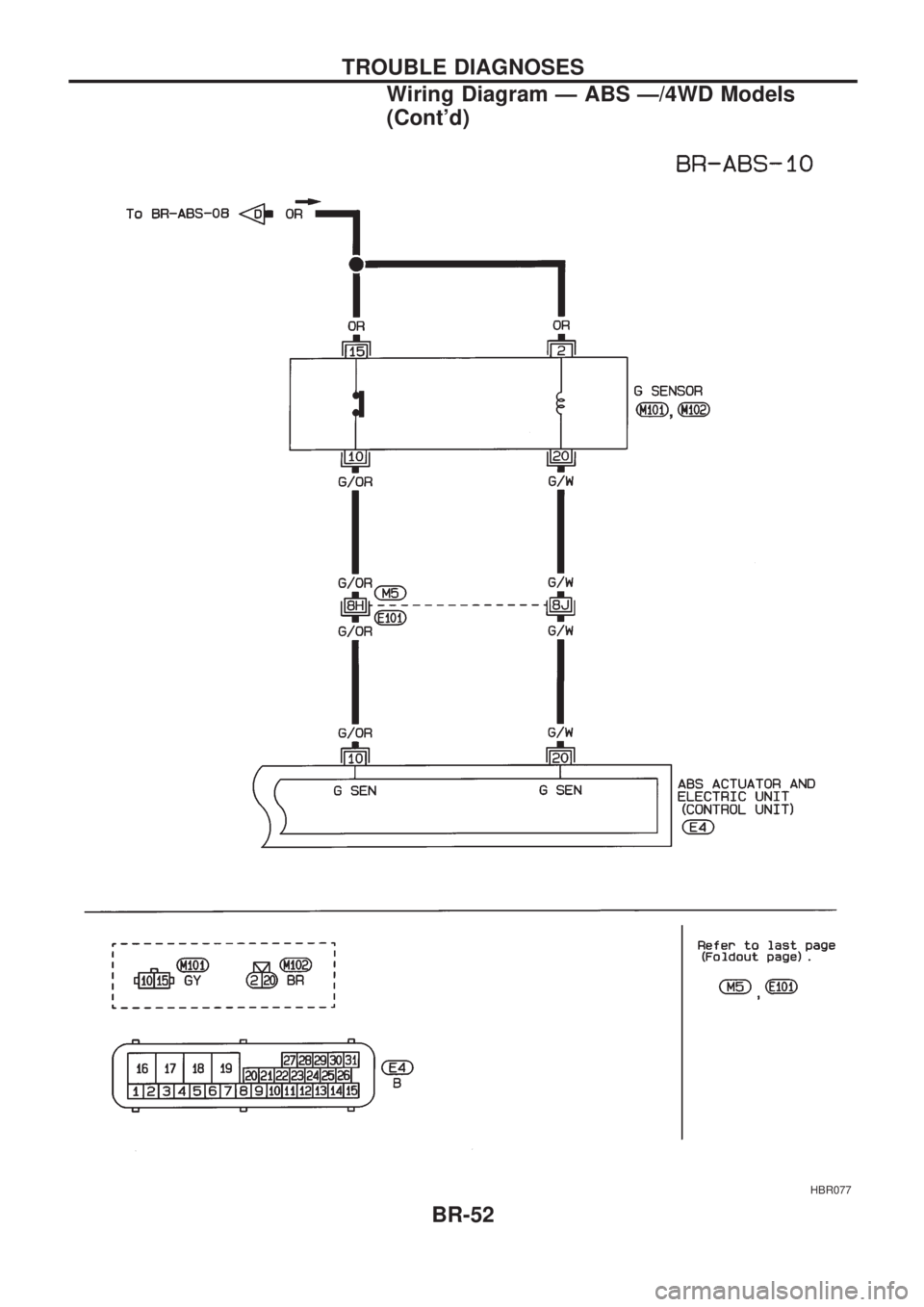
HBR077
TROUBLE DIAGNOSES
Wiring Diagram Ð ABS Ð/4WD Models
(Cont'd)
BR-52
Page 78 of 1659
Diagnostic Procedure 10
(ABS does not work.)
CHECK WARNING LAMP ACTIVATE.
-------------------------------------------------------------------------------------------------------------------------------------------------------------------------------------------------------------------------------------------------------------------------------------------------------------
Does the ABS warning lamp activate?
No
cYes
Carry out self-diagnosis.
Refer to BR-53, 57.
Go toin Diagnostic Procedure 8,
BR-73.
Note: ABS does not work when vehicle speed is under 10
km/h (6 MPH).
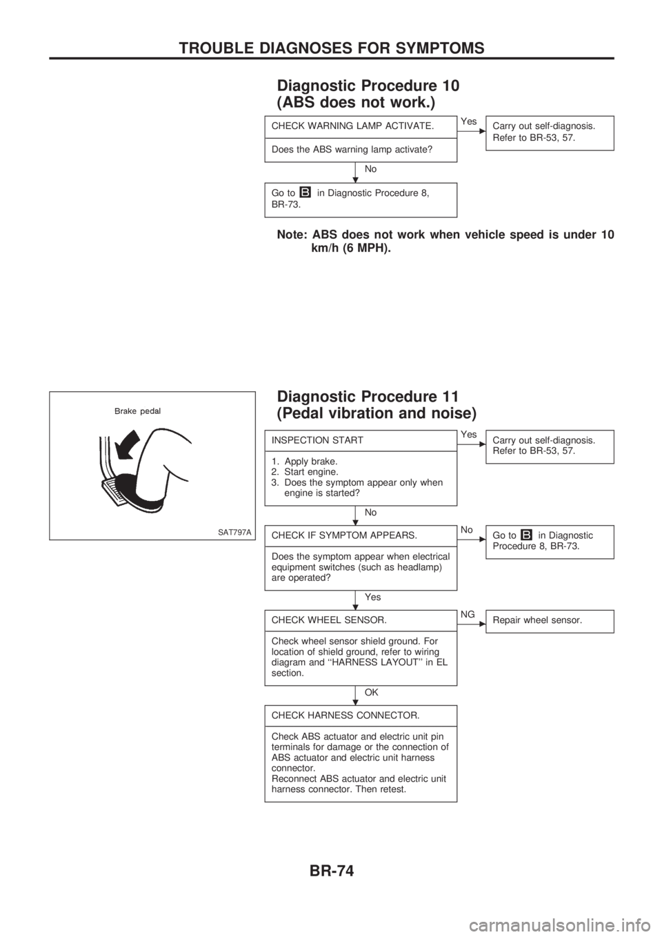
Diagnostic Procedure 11
(Pedal vibration and noise)
INSPECTION START
-------------------------------------------------------------------------------------------------------------------------------------------------------------------------------------------------------------------------------------------------------------------------------------------------------------
1. Apply brake.
2. Start engine.
3. Does the symptom appear only when
engine is started?
No
cYes
Carry out self-diagnosis.
Refer to BR-53, 57.
CHECK IF SYMPTOM APPEARS.
-------------------------------------------------------------------------------------------------------------------------------------------------------------------------------------------------------------------------------------------------------------------------------------------------------------
Does the symptom appear when electrical
equipment switches (such as headlamp)
are operated?
Yes
cNo
Go toin Diagnostic
Procedure 8, BR-73.
CHECK WHEEL SENSOR.
-------------------------------------------------------------------------------------------------------------------------------------------------------------------------------------------------------------------------------------------------------------------------------------------------------------
Check wheel sensor shield ground. For
location of shield ground, refer to wiring
diagram and ``HARNESS LAYOUT'' in EL
section.
OK
cNG
Repair wheel sensor.
CHECK HARNESS CONNECTOR.
-------------------------------------------------------------------------------------------------------------------------------------------------------------------------------------------------------------------------------------------------------------------------------------------------------------
Check ABS actuator and electric unit pin
terminals for damage or the connection of
ABS actuator and electric unit harness
connector.
Reconnect ABS actuator and electric unit
harness connector. Then retest.
SAT797A
.
.
.
.
TROUBLE DIAGNOSES FOR SYMPTOMS
BR-74
Page 100 of 1659
BODY & TRIM
SECTIONBT
CONTENTS
PRECAUTIONS......................................................... 1
Service Notice ........................................................ 1
Supplemental Restraint System (SRS) ``AIR
BAG'' (4WD models).............................................. 1
Supplemental Restraint System (SRS) ``AIR
BAG'' (2WD models).............................................. 1
GENERAL SERVICING............................................. 2
Clip and Fastener .................................................. 2
BODY END................................................................ 5
Body Front End ...................................................... 5
Body Rear End ...................................................... 8
DOOR....................................................................... 10
Front Door ............................................................ 10
Rear Door ............................................................ 11
INSTRUMENT PANEL............................................. 12
INTERIOR TRIM...................................................... 15
Side and Floor Trim ............................................. 15
Door Trim ............................................................. 18
Roof Trim ............................................................. 21EXTERIOR............................................................... 24
SEAT........................................................................ 30
Front Seat ............................................................ 30
Heated Seat ......................................................... 32
Rear Seat ............................................................. 33
Jump Seat ............................................................ 34
SUNROOF................................................................ 35
WINDSHIELD AND WINDOWS.............................. 36
Windshield............................................................ 37
Side Window ........................................................ 38
MIRROR................................................................... 39
Door Mirror ........................................................... 39
CAB AND REAR BODY.......................................... 40
Removal ............................................................... 40
Body Mounting ..................................................... 41
BODY ALIGNMENT................................................. 43
Engine Compartment ........................................... 44
Underbody............................................................ 46
.For seat belt, refer to MA and RS section.
.For wiring diagrams of body electrical systems, refer to EL section.BT
Page 132 of 1659
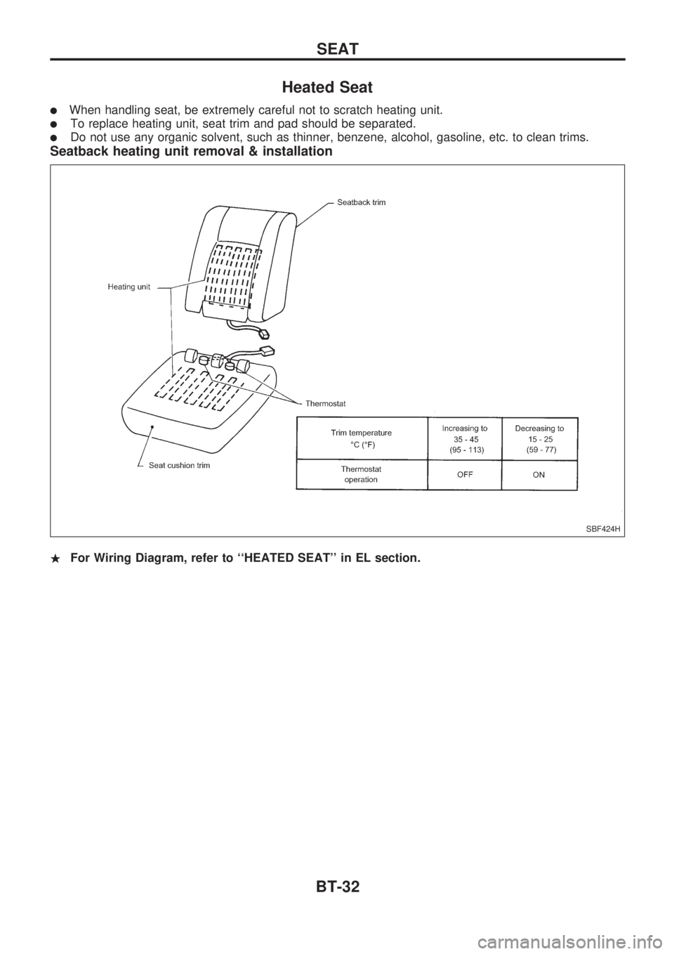
Heated Seat
lWhen handling seat, be extremely careful not to scratch heating unit.
lTo replace heating unit, seat trim and pad should be separated.
lDo not use any organic solvent, such as thinner, benzene, alcohol, gasoline, etc. to clean trims.
Seatback heating unit removal & installation
.For Wiring Diagram, refer to ``HEATED SEAT'' in EL section.
SBF424H
SEAT
BT-32
Page 139 of 1659

Door MirrorCAUTION:
Be careful not to scratch door rearview mirror body.
.For Wiring Diagram, refer to ``POWER DOOR MIRROR'' in EL section.
REMOVAL Ð Door mirror
V1Remove door trim. Refer to ``Door Trim'' for details, BT-18.
V2Remove inner cover from front corner of door.
V3Disconnect door mirror harness connector.
V4Remove bolts securing door mirror, then remove door mirror assembly.
SBT458
MIRROR
BT-39
Page 151 of 1659

TROUBLE DIAGNOSIS FOR POWER SUPPLY.... 75
Main Power Supply and Ground Circuit .............. 75
TROUBLE DIAGNOSIS FOR ``CAMSHAFT
POSI SEN'' (DTC 11).............................................. 82
Camshaft Position Sensor (CMPS) ..................... 82
TROUBLE DIAGNOSIS FOR ``MASS AIR
FLOW SEN'' (DTC 12)............................................ 89
Mass Air Flow Sensor (MAFS) ............................ 89
TROUBLE DIAGNOSIS FOR ``COOLANT TEMP
SEN'' (DTC 13)........................................................ 95
Engine Coolant Temperature Sensor (ECTS) ..... 95
TROUBLE DIAGNOSIS FOR ``IGN SIGNAL-
PRIMARY'' (DTC 21)............................................... 99
Ignition Signal ...................................................... 99
TROUBLE DIAGNOSIS FOR ``OVER HEAT''
(DTC 28)................................................................. 106
Overheat ............................................................ 106
TROUBLE DIAGNOSIS FOR ``INT AIR TEMP
SEN'' (DTC 41)...................................................... 109
Intake Air Temperature Sensor ......................... 109
TROUBLE DIAGNOSIS FOR ``THROTTLE POSI
SEN'' (DTC 43)...................................................... 113
Throttle Position Sensor .................................... 113
TROUBLE DIAGNOSIS FOR
NON-DETECTABLE ITEMS.................................. 118
Vehicle Speed Sensor (VSS) ............................ 118
Heated Oxygen Sensor (HO2S)
- LHD Models - .................................................. 123
Heated Oxygen Sensor Heater
- LHD Models - .................................................. 127
Idle Air Control Valve (IACV) - Auxiliary Air
Control (AAC) Valve .......................................... 131
Neutral Position Switch ...................................... 136
EVAP Canister Purge Control Solenoid Valve .. 140
Injector ............................................................... 144
Start Signal ........................................................ 149
Fuel Pump.......................................................... 151
Power Steering Oil Pressure Switch ................. 157
Swirl Control Valve Control Solenoid Valve ...... 161
IACV-FICD Solenoid Valve ................................ 168
MIL & Data Link Connectors ............................. 173
TD
INJECTION SYSTEM............................................ 176
Fuel System ....................................................... 176
INJECTION PUMP................................................. 178
Inspection ........................................................... 178
Removal ............................................................. 178
Installation and Adjustment................................ 180
Disassembly ....................................................... 183
Load Timer Adjustment...................................... 183
Start Q Adjustment Lever .................................. 184
INJECTION NOZZLE............................................. 186Removal and Installation ................................... 186
Disassembly ....................................................... 186
Inspection ........................................................... 187
Cleaning ............................................................. 187
Assembly............................................................ 189
Test and Adjustment .......................................... 189
FUEL SYSTEM CHECK........................................ 191
Bleeding Fuel System ........................................ 191
Bleeding Fuel Filter ............................................ 192
Checking Priming Pump .................................... 192
Checking Fuel Filter Switch ............................... 192
POSITIVE CRANKCASE VENTILATION.............. 193
Description ......................................................... 193
Inspection ........................................................... 193
QUICK-GLOW SYSTEM........................................ 194
Component Parts Location ................................ 194
Circuit Diagram .................................................. 195
Description ......................................................... 196
Wiring Diagram .................................................. 197
Glow Control Unit Circuit Inspection (For Cold
Areas)................................................................. 203
Glow Control Unit Circuit Inspection (Except
for Cold Areas)................................................... 206
Component Inspection ....................................... 208
EGR SYSTEM........................................................ 210
Component Parts Location ................................ 210
Description ......................................................... 211
Operation ........................................................... 212
Wiring Diagram .................................................. 213
System Inspection.............................................. 217
Component Inspection ....................................... 218
SOLENOID TIMER................................................ 220
Description ......................................................... 220
Operation ........................................................... 220
Wiring Diagram .................................................. 222
Inspection ........................................................... 224
FUEL CUT SYSTEM.............................................. 225
Wiring Diagram .................................................. 225
FUEL HEATER SYSTEM...................................... 226
Description ......................................................... 226
Wiring Diagram .................................................. 227
System Inspection.............................................. 228
Component Inspection ....................................... 228
FAST IDLE CONTROL CIRCUIT.......................... 230
Wiring Diagram .................................................. 230
Electrical Components Inspection ..................... 231
KA
SERVICE DATA AND SPECIFICATIONS (SDS). 232
General Specifications ....................................... 232
Inspection and Adjustment ................................ 232