1998 NISSAN PICK-UP service indicator
[x] Cancel search: service indicatorPage 741 of 1659

CRANKSHAFT
SEM394EM715
Unit: mm (in)
Main journal diameter (Dm) GradeNo. 0 59.967 - 59.975 (2.3609 - 2.3612)
No. 1 59.959 - 59.967 (2.3606 - 2.3609)
No. 2 59.951 - 59.959 (2.3603 - 2.3606)
Pin journal diameter (Dp) GradeNo. 0 49.968 - 49.974 (1.9672 - 1.9675)
No. 1 49.962 - 49.968 (1.9670 - 1.9672)
No. 2 49.956 - 49.962 (1.9668 - 1.9670)
Center distance (r) 47.95 - 48.05 (1.8878 - 1.8917)
Standard Limit
Taper of journal and pin [
VA±VB]Journal Ð 0.01 (0.0004)
Pin Ð 0.005 (0.0002)
Out-of-round of journal and pin
[
VX±VY]Journal Ð 0.01 (0.0004)
Pin Ð 0.005 (0.0002)
Runout [TIR]* Ð 0.10 (0.0039)
Free end play 0.05 - 0.18 (0.0020 - 0.0071) 0.3 (0.012)
Fillet roilMore than 0.1 (0.004)
* Total indicator reading
BEARING CLEARANCE
Unit: mm (in)
Standard Limit
Main bearing clearance0.020 - 0.047
(0.0008 - 0.0019)0.1 (0.004)
Connecting rod bearing
clearance0.010 - 0.035
(0.0004 - 0.0014)0.09 (0.0035)
SERVICE DATA AND SPECIFICATIONS (SDS)KA
Inspection and Adjustment (Cont'd)
EM-96
Page 742 of 1659
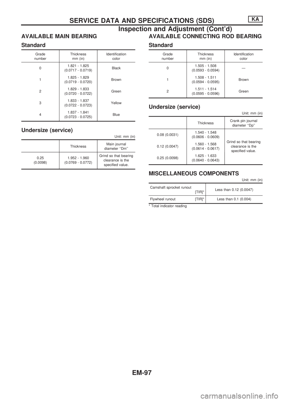
AVAILABLE MAIN BEARING
Standard
Grade
numberThickness
mm (in)Identification
color
01.821 - 1.825
(0.0717 - 0.0719)Black
11.825 - 1.829
(0.0719 - 0.0720)Brown
21.829 - 1.833
(0.0720 - 0.0722)Green
31.833 - 1.837
(0.0722 - 0.0723)Yellow
41.837 - 1.841
(0.0723 - 0.0725)Blue
Undersize (service)
Unit: mm (in)
ThicknessMain journal
diameter ``Dm''
0.25
(0.0098)1.952 - 1.960
(0.0769 - 0.0772)Grind so that bearing
clearance is the
specified value.
AVAILABLE CONNECTING ROD BEARING
Standard
Grade
numberThickness
mm (in)Identification
color
01.505 - 1.508
(0.0593 - 0.0594)Ð
11.508 - 1.511
(0.0594 - 0.0595)Brown
21.511 - 1.514
(0.0595 - 0.0596)Green
Undersize (service)
Unit: mm (in)
ThicknessCrank pin journal
diameter ``Dp''
0.08 (0.0031)1.540 - 1.548
(0.0606 - 0.0609)
Grind so that bearing
clearance is the
specified value. 0.12 (0.0047)1.560 - 1.568
(0.0614 - 0.0617)
0.25 (0.0098)1.625 - 1.633
(0.0640 - 0.0643)
MISCELLANEOUS COMPONENTS
Unit: mm (in)
Camshaft sprocket runout
[TIR]*Less than 0.12 (0.0047)
Flywheel runout [TIR]* Less than 0.1 (0.004)
* Total indicator reading
SERVICE DATA AND SPECIFICATIONS (SDS)KA
Inspection and Adjustment (Cont'd)
EM-97
Page 744 of 1659
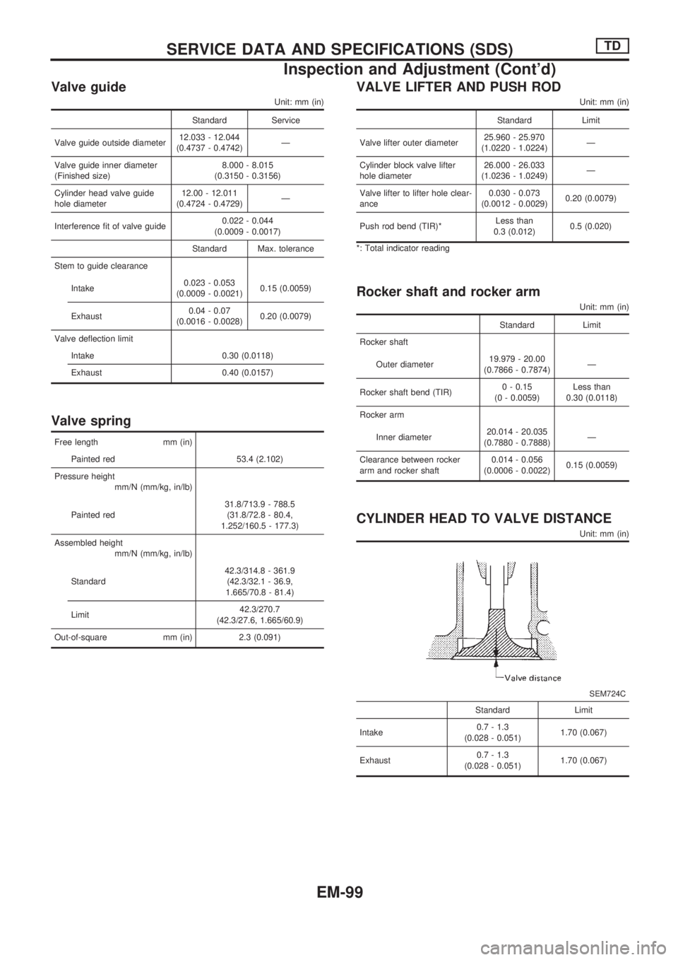
Valve guide
Unit: mm (in)
Standard Service
Valve guide outside diameter12.033 - 12.044
(0.4737 - 0.4742)Ð
Valve guide inner diameter
(Finished size)8.000 - 8.015
(0.3150 - 0.3156)
Cylinder head valve guide
hole diameter12.00 - 12.011
(0.4724 - 0.4729)Ð
Interference fit of valve guide0.022 - 0.044
(0.0009 - 0.0017)
Standard Max. tolerance
Stem to guide clearance
Intake0.023 - 0.053
(0.0009 - 0.0021)0.15 (0.0059)
Exhaust0.04 - 0.07
(0.0016 - 0.0028)0.20 (0.0079)
Valve deflection limit
Intake 0.30 (0.0118)
Exhaust 0.40 (0.0157)
Valve spring
Free length mm (in)
Painted red 53.4 (2.102)
Pressure height
mm/N (mm/kg, in/lb)
Painted red31.8/713.9 - 788.5
(31.8/72.8 - 80.4,
1.252/160.5 - 177.3)
Assembled height
mm/N (mm/kg, in/lb)
Standard42.3/314.8 - 361.9
(42.3/32.1 - 36.9,
1.665/70.8 - 81.4)
Limit42.3/270.7
(42.3/27.6, 1.665/60.9)
Out-of-square mm (in) 2.3 (0.091)
VALVE LIFTER AND PUSH ROD
Unit: mm (in)
Standard Limit
Valve lifter outer diameter25.960 - 25.970
(1.0220 - 1.0224)Ð
Cylinder block valve lifter
hole diameter26.000 - 26.033
(1.0236 - 1.0249)Ð
Valve lifter to lifter hole clear-
ance0.030 - 0.073
(0.0012 - 0.0029)0.20 (0.0079)
Push rod bend (TIR)*Less than
0.3 (0.012)0.5 (0.020)
*: Total indicator reading
Rocker shaft and rocker arm
Unit: mm (in)
Standard Limit
Rocker shaft
Outer diameter19.979 - 20.00
(0.7866 - 0.7874)Ð
Rocker shaft bend (TIR)0 - 0.15
(0 - 0.0059)Less than
0.30 (0.0118)
Rocker arm
Inner diameter20.014 - 20.035
(0.7880 - 0.7888)Ð
Clearance between rocker
arm and rocker shaft0.014 - 0.056
(0.0006 - 0.0022)0.15 (0.0059)
CYLINDER HEAD TO VALVE DISTANCE
Unit: mm (in)
SEM724C
Standard Limit
Intake0.7 - 1.3
(0.028 - 0.051)1.70 (0.067)
Exhaust0.7 - 1.3
(0.028 - 0.051)1.70 (0.067)
SERVICE DATA AND SPECIFICATIONS (SDS)TD
Inspection and Adjustment (Cont'd)
EM-99
Page 746 of 1659
![NISSAN PICK-UP 1998 Repair Manual CAMSHAFT AND CAMSHAFT BEARING
Unit: mm (in)
Standard Limit
Camshaft journal to bush-
ing clearance
[Oil clearance]0.020 - 0.109
(0.0008 - 0.0043)0.15 (0.0059)
Camshaft journal diam-
eter
Front50.721 - NISSAN PICK-UP 1998 Repair Manual CAMSHAFT AND CAMSHAFT BEARING
Unit: mm (in)
Standard Limit
Camshaft journal to bush-
ing clearance
[Oil clearance]0.020 - 0.109
(0.0008 - 0.0043)0.15 (0.0059)
Camshaft journal diam-
eter
Front50.721 -](/manual-img/5/57374/w960_57374-745.png)
CAMSHAFT AND CAMSHAFT BEARING
Unit: mm (in)
Standard Limit
Camshaft journal to bush-
ing clearance
[Oil clearance]0.020 - 0.109
(0.0008 - 0.0043)0.15 (0.0059)
Camshaft journal diam-
eter
Front50.721 - 50.740
(1.9969 - 1.9976)Ð
2nd50.521 - 50.540
(1.9890 - 1.9898)Ð
3rd50.321 - 50.340
(1.9811 - 1.9819)Ð
4th50.121 - 50.140
(1.9733 - 1.9740)Ð
Rear49.921 - 49.940
(1.9654 - 1.9661)Ð
Camshaft bend (Total
indicator reading)Less than
0.02 (0.0008)0.06 (0.0024)
Camshaft end play0.08 - 0.28
(0.0031 - 0.0110)0.50 (0.0197)
EM671
Standard Limit
Cam height ``A''
Intake & Exhaust41.88 - 41.92
(1.6488 - 1.6504)41.40 (1.6299)
SERVICE DATA AND SPECIFICATIONS (SDS)TD
Inspection and Adjustment (Cont'd)
EM-101
Page 751 of 1659
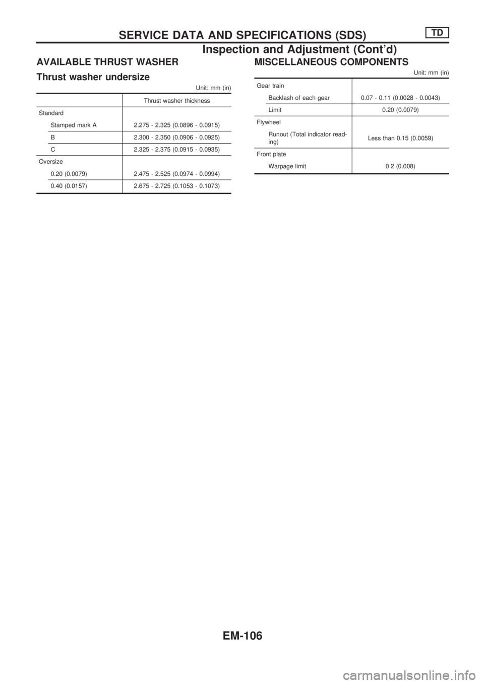
AVAILABLE THRUST WASHER
Thrust washer undersize
Unit: mm (in)
Thrust washer thickness
Standard
Stamped mark A 2.275 - 2.325 (0.0896 - 0.0915)
B 2.300 - 2.350 (0.0906 - 0.0925)
C 2.325 - 2.375 (0.0915 - 0.0935)
Oversize
0.20 (0.0079) 2.475 - 2.525 (0.0974 - 0.0994)
0.40 (0.0157) 2.675 - 2.725 (0.1053 - 0.1073)
MISCELLANEOUS COMPONENTS
Unit: mm (in)
Gear train
Backlash of each gear 0.07 - 0.11 (0.0028 - 0.0043)
Limit 0.20 (0.0079)
Flywheel
Runout (Total indicator read-
ing)Less than 0.15 (0.0059)
Front plate
Warpage limit 0.2 (0.008)
SERVICE DATA AND SPECIFICATIONS (SDS)TD
Inspection and Adjustment (Cont'd)
EM-106
Page 806 of 1659
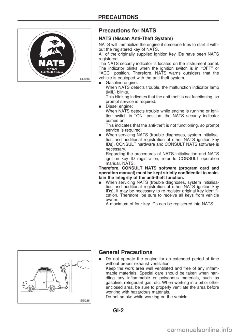
Precautions for NATS
NATS (Nissan Anti-Theft System)
NATS will immobilize the engine if someone tries to start it with-
out the registered key of NATS.
All of the originally supplied ignition key IDs have been NATS
registered.
The NATS security indicator is located on the instrument panel.
The indicator blinks when the ignition switch is in ``OFF'' or
``ACC'' position. Therefore, NATS warns outsiders that the
vehicle is equipped with the anti-theft system.
lGasoline engine:
When NATS detects trouble, the malfunction indicator lamp
(MIL) blinks.
This blinking indicates that the anti-theft is not functioning, so
prompt service is required.
lDiesel engine:
When NATS detects trouble while engine is running or igni-
tion switch in ``ON'' position, the NATS security indicator
comes on.
This indicates that the anti-theft is not functioning, so prompt
service is required.
lWhen servicing NATS (trouble diagnoses, system initialisa-
tion and additional registration of other NATS ignition key
IDs), CONSULT hardware and CONSULT NATS software is
necessary.
Regarding the procedures of NATS initialisation and NATS
ignition key ID registration, refer to CONSULT operation
manual, NATS.
Therefore, CONSULT NATS software (program card and
operation manual) must be kept strictly confidential to main-
tain the integrity of the anti-theft function.
lWhen servicing NATS (trouble diagnoses, system initialisa-
tion and additional registration of other NATS ignition key
IDs), it may be necessary to re-register original key identifi-
cation. Therefore, be sure to receive all keys from vehicle
owner.
A maximum of four key IDs can be registered into NATS.
General Precautions
lDo not operate the engine for an extended period of time
without proper exhaust ventilation.
Keep the work area well ventilated and free of any inflam-
mable materials. Special care should be taken when han-
dling any inflammable or poisonous materials, such as
gasoline, refrigerant gas, etc. When working in a pit or other
enclosed area, be sure to properly ventilate the area before
working with hazardous materials.
Do not smoke while working on the vehicle.
SGI916
SGI285
PRECAUTIONS
GI-2
Page 861 of 1659
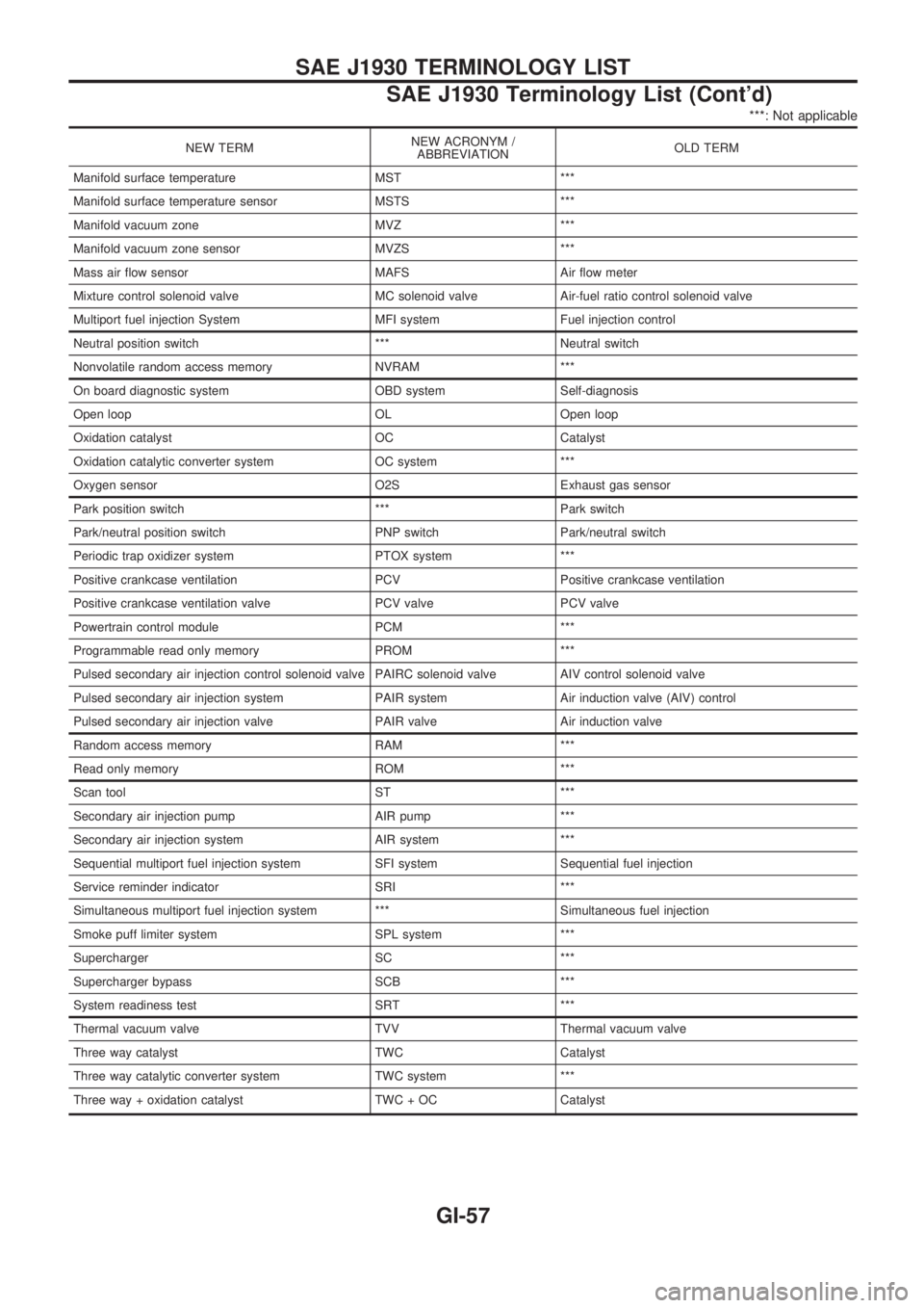
***: Not applicable
NEW TERMNEW ACRONYM /
ABBREVIATIONOLD TERM
Manifold surface temperature MST ***
Manifold surface temperature sensor MSTS ***
Manifold vacuum zone MVZ ***
Manifold vacuum zone sensor MVZS ***
Mass air flow sensor MAFS Air flow meter
Mixture control solenoid valve MC solenoid valve Air-fuel ratio control solenoid valve
Multiport fuel injection System MFI system Fuel injection control
Neutral position switch *** Neutral switch
Nonvolatile random access memory NVRAM ***
On board diagnostic system OBD system Self-diagnosis
Open loop OL Open loop
Oxidation catalyst OC Catalyst
Oxidation catalytic converter system OC system ***
Oxygen sensor O2S Exhaust gas sensor
Park position switch *** Park switch
Park/neutral position switch PNP switch Park/neutral switch
Periodic trap oxidizer system PTOX system ***
Positive crankcase ventilation PCV Positive crankcase ventilation
Positive crankcase ventilation valve PCV valve PCV valve
Powertrain control module PCM ***
Programmable read only memory PROM ***
Pulsed secondary air injection control solenoid valve PAIRC solenoid valve AIV control solenoid valve
Pulsed secondary air injection system PAIR system Air induction valve (AIV) control
Pulsed secondary air injection valve PAIR valve Air induction valve
Random access memory RAM ***
Read only memory ROM ***
Scan tool ST ***
Secondary air injection pump AIR pump ***
Secondary air injection system AIR system ***
Sequential multiport fuel injection system SFI system Sequential fuel injection
Service reminder indicator SRI ***
Simultaneous multiport fuel injection system *** Simultaneous fuel injection
Smoke puff limiter system SPL system ***
Supercharger SC ***
Supercharger bypass SCB ***
System readiness test SRT ***
Thermal vacuum valve TVV Thermal vacuum valve
Three way catalyst TWC Catalyst
Three way catalytic converter system TWC system ***
Three way + oxidation catalyst TWC + OC Catalyst
SAE J1930 TERMINOLOGY LIST
SAE J1930 Terminology List (Cont'd)
GI-57
Page 1079 of 1659
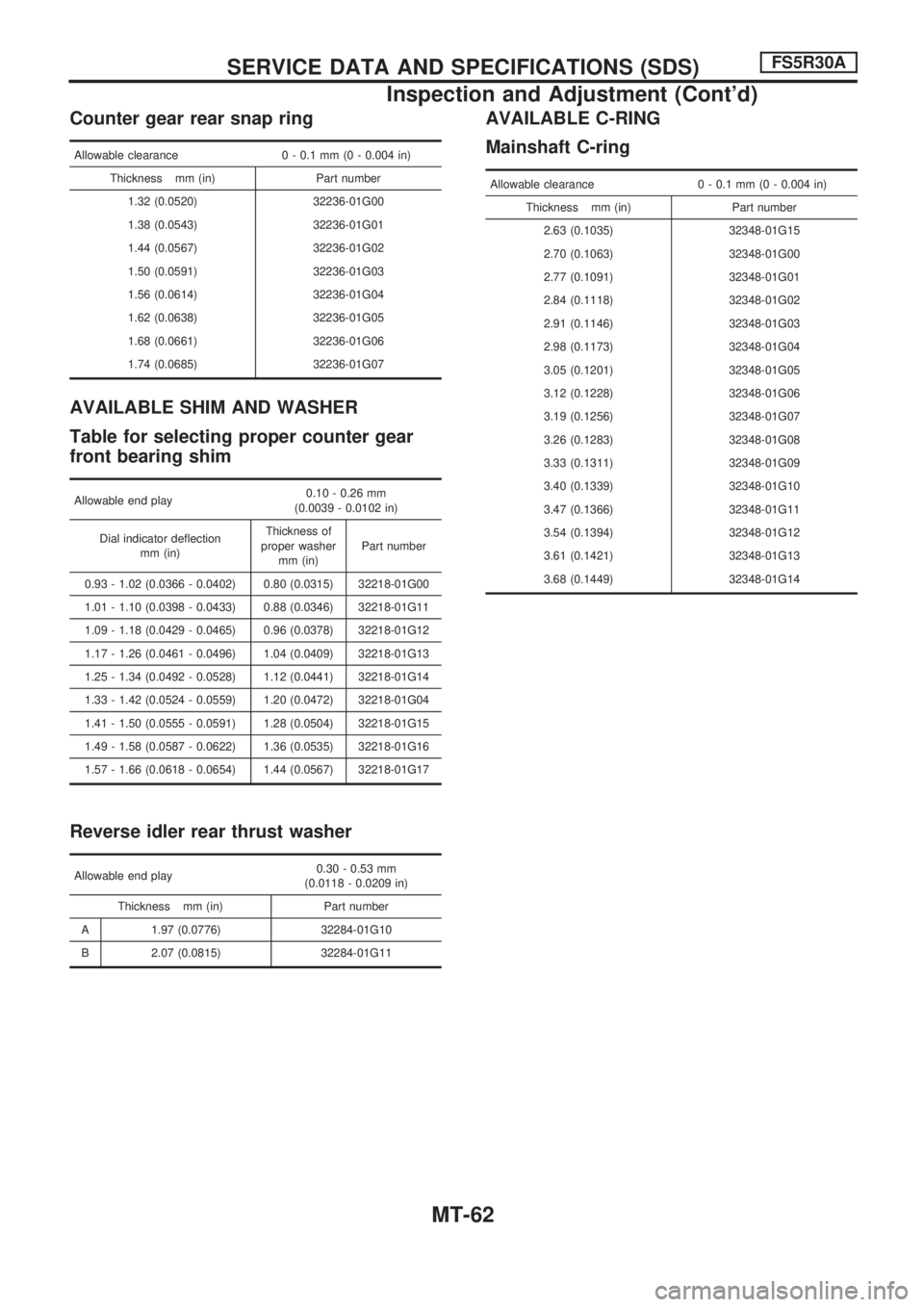
Counter gear rear snap ring
Allowable clearance 0 - 0.1 mm (0 - 0.004 in)
Thickness mm (in) Part number
1.32 (0.0520) 32236-01G00
1.38 (0.0543) 32236-01G01
1.44 (0.0567) 32236-01G02
1.50 (0.0591) 32236-01G03
1.56 (0.0614) 32236-01G04
1.62 (0.0638) 32236-01G05
1.68 (0.0661) 32236-01G06
1.74 (0.0685) 32236-01G07
AVAILABLE SHIM AND WASHER
Table for selecting proper counter gear
front bearing shim
Allowable end play0.10 - 0.26 mm
(0.0039 - 0.0102 in)
Dial indicator deflection
mm (in)Thickness of
proper washer
mm (in)Part number
0.93 - 1.02 (0.0366 - 0.0402) 0.80 (0.0315) 32218-01G00
1.01 - 1.10 (0.0398 - 0.0433) 0.88 (0.0346) 32218-01G11
1.09 - 1.18 (0.0429 - 0.0465) 0.96 (0.0378) 32218-01G12
1.17 - 1.26 (0.0461 - 0.0496) 1.04 (0.0409) 32218-01G13
1.25 - 1.34 (0.0492 - 0.0528) 1.12 (0.0441) 32218-01G14
1.33 - 1.42 (0.0524 - 0.0559) 1.20 (0.0472) 32218-01G04
1.41 - 1.50 (0.0555 - 0.0591) 1.28 (0.0504) 32218-01G15
1.49 - 1.58 (0.0587 - 0.0622) 1.36 (0.0535) 32218-01G16
1.57 - 1.66 (0.0618 - 0.0654) 1.44 (0.0567) 32218-01G17
Reverse idler rear thrust washer
Allowable end play0.30 - 0.53 mm
(0.0118 - 0.0209 in)
Thickness mm (in) Part number
A 1.97 (0.0776) 32284-01G10
B 2.07 (0.0815) 32284-01G11
AVAILABLE C-RING
Mainshaft C-ring
Allowable clearance 0 - 0.1 mm (0 - 0.004 in)
Thickness mm (in) Part number
2.63 (0.1035) 32348-01G15
2.70 (0.1063) 32348-01G00
2.77 (0.1091) 32348-01G01
2.84 (0.1118) 32348-01G02
2.91 (0.1146) 32348-01G03
2.98 (0.1173) 32348-01G04
3.05 (0.1201) 32348-01G05
3.12 (0.1228) 32348-01G06
3.19 (0.1256) 32348-01G07
3.26 (0.1283) 32348-01G08
3.33 (0.1311) 32348-01G09
3.40 (0.1339) 32348-01G10
3.47 (0.1366) 32348-01G11
3.54 (0.1394) 32348-01G12
3.61 (0.1421) 32348-01G13
3.68 (0.1449) 32348-01G14
SERVICE DATA AND SPECIFICATIONS (SDS)FS5R30A
Inspection and Adjustment (Cont'd)
MT-62