Page 1486 of 1659

Trouble Diagnoses
WORK FLOW
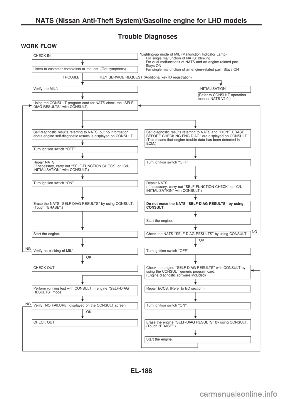
CHECK IN*Lighting-up mode of MIL (Malfunction Indicator Lamp)
For single malfunction of NATS: Blinking
For dual malfunctions of NATS and an engine-related part:
Stays ON
For single malfunction of an engine-related part: Stays ON Listen to customer complaints or request. (Get symptoms)
TROUBLE KEY SERVICE REQUEST (Additional key ID registration)
.Verify the MIL*.INITIALISATION
(Refer to CONSULT operation
manual NATS V2.0.)
cUsing the CONSULT program card for NATS check the ``SELF-
DIAG RESULTS'' with CONSULT.b
Self-diagnostic results referring to NATS, but no information
about engine self-diagnostic results is displayed on CONSULT.Self-diagnostic results referring to NATS and ``DON'T ERASE
BEFORE CHECKING ENG DIAG'' are displayed on CONSULT.
(This means that engine trouble data has been detected in
ECM.)
Turn ignition switch ``OFF''.
Repair NATS.
(If necessary, carry out ``SELF-FUNCTION CHECK'' or ``C/U
INITIALISATION'' with CONSULT.)Turn ignition switch ``OFF''.
Turn ignition switch ``ON''.Repair NATS.
(If necessary, carry out ``SELF-FUNCTION CHECK'' or ``C/U
INITIALISATION'' with CONSULT.)
Erase the NATS ``SELF-DIAG RESULTS'' by using CONSULT.
(Touch ``ERASE''.)Do not erase the NATS ``SELF-DIAG RESULTS'' by using
CONSULT.
Start the engine.
Start the engine.Check the NATS ``SELF-DIAG RESULTS'' by using CONSULT.
OKNG
NGVerify no blinking of MIL*.
OKTurn ignition switch ``OFF''.
CHECK OUTCheck the engine ``SELF-DIAG RESULTS'' with CONSULT by
using the CONSULT generic program card.
(Engine diagnostic software included)b
Perform running test with CONSULT in engine ``SELF-DIAG
RESULTS'' mode.Repair ECCS. (Refer to EC section.)
NGVerify ``NO FAILURE'' displayed on the CONSULT screen.
OKTurn ignition switch ``ON''.
CHECK OUTErase the engine ``SELF-DIAG RESULTS'' by using CONSULT.
(Touch ``ERASE''.)
Start the engine.
.
.
.
..
.
..
..
..
.
..
..
..
..
..
..
.
NATS (Nissan Anti-Theft System)/Gasoline engine for LHD models
EL-188
Page 1649 of 1659

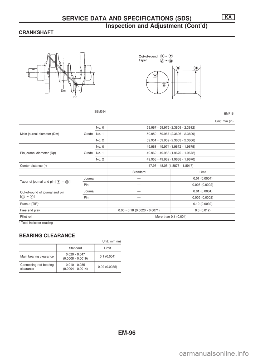
CRANKSHAFT
SEM394EM715
Unit: mm (in)
Main journal diameter (Dm) GradeNo. 0 59.967 - 59.975 (2.3609 - 2.3612)
No. 1 59.959 - 59.967 (2.3606 - 2.3609)
No. 2 59.951 - 59.959 (2.3603 - 2.3606)
Pin journal diameter (Dp) GradeNo. 0 49.968 - 49.974 (1.9672 - 1.9675)
No. 1 49.962 - 49.968 (1.9670 - 1.9672)
No. 2 49.956 - 49.962 (1.9668 - 1.9670)
Center distance (r) 47.95 - 48.05 (1.8878 - 1.8917)
Standard Limit
Taper of journal and pin [
VA±VB]Journal Ð 0.01 (0.0004)
Pin Ð 0.005 (0.0002)
Out-of-round of journal and pin
[
VX±VY]Journal Ð 0.01 (0.0004)
Pin Ð 0.005 (0.0002)
Runout [TIR]* Ð 0.10 (0.0039)
Free end play 0.05 - 0.18 (0.0020 - 0.0071) 0.3 (0.012)
Fillet roilMore than 0.1 (0.004)
* Total indicator reading
BEARING CLEARANCE
Unit: mm (in)
Standard Limit
Main bearing clearance0.020 - 0.047
(0.0008 - 0.0019)0.1 (0.004)
Connecting rod bearing
clearance0.010 - 0.035
(0.0004 - 0.0014)0.09 (0.0035)
SERVICE DATA AND SPECIFICATIONS (SDS)KA
Inspection and Adjustment (Cont'd)
EM-96
Page 1650 of 1659

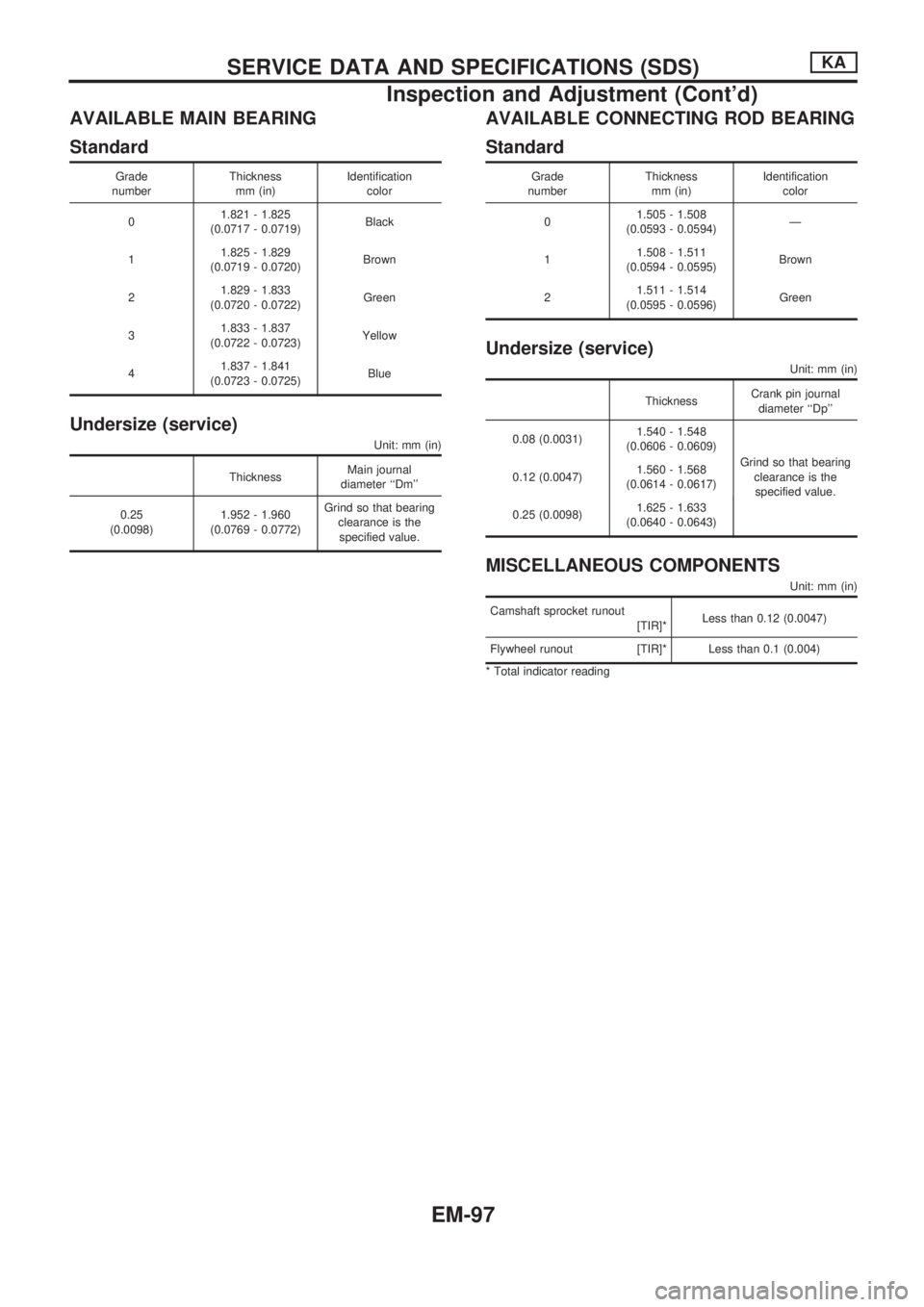
AVAILABLE MAIN BEARING
Standard
Grade
numberThickness
mm (in)Identification
color
01.821 - 1.825
(0.0717 - 0.0719)Black
11.825 - 1.829
(0.0719 - 0.0720)Brown
21.829 - 1.833
(0.0720 - 0.0722)Green
31.833 - 1.837
(0.0722 - 0.0723)Yellow
41.837 - 1.841
(0.0723 - 0.0725)Blue
Undersize (service)
Unit: mm (in)
ThicknessMain journal
diameter ``Dm''
0.25
(0.0098)1.952 - 1.960
(0.0769 - 0.0772)Grind so that bearing
clearance is the
specified value.
AVAILABLE CONNECTING ROD BEARING
Standard
Grade
numberThickness
mm (in)Identification
color
01.505 - 1.508
(0.0593 - 0.0594)Ð
11.508 - 1.511
(0.0594 - 0.0595)Brown
21.511 - 1.514
(0.0595 - 0.0596)Green
Undersize (service)
Unit: mm (in)
ThicknessCrank pin journal
diameter ``Dp''
0.08 (0.0031)1.540 - 1.548
(0.0606 - 0.0609)
Grind so that bearing
clearance is the
specified value. 0.12 (0.0047)1.560 - 1.568
(0.0614 - 0.0617)
0.25 (0.0098)1.625 - 1.633
(0.0640 - 0.0643)
MISCELLANEOUS COMPONENTS
Unit: mm (in)
Camshaft sprocket runout
[TIR]*Less than 0.12 (0.0047)
Flywheel runout [TIR]* Less than 0.1 (0.004)
* Total indicator reading
SERVICE DATA AND SPECIFICATIONS (SDS)KA
Inspection and Adjustment (Cont'd)
EM-97
Page 1652 of 1659

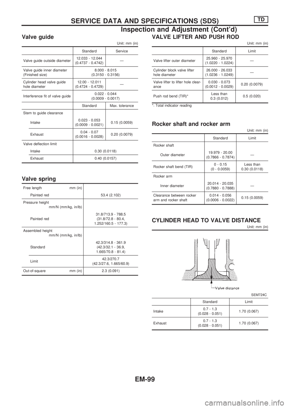
Valve guide
Unit: mm (in)
Standard Service
Valve guide outside diameter12.033 - 12.044
(0.4737 - 0.4742)Ð
Valve guide inner diameter
(Finished size)8.000 - 8.015
(0.3150 - 0.3156)
Cylinder head valve guide
hole diameter12.00 - 12.011
(0.4724 - 0.4729)Ð
Interference fit of valve guide0.022 - 0.044
(0.0009 - 0.0017)
Standard Max. tolerance
Stem to guide clearance
Intake0.023 - 0.053
(0.0009 - 0.0021)0.15 (0.0059)
Exhaust0.04 - 0.07
(0.0016 - 0.0028)0.20 (0.0079)
Valve deflection limit
Intake 0.30 (0.0118)
Exhaust 0.40 (0.0157)
Valve spring
Free length mm (in)
Painted red 53.4 (2.102)
Pressure height
mm/N (mm/kg, in/lb)
Painted red31.8/713.9 - 788.5
(31.8/72.8 - 80.4,
1.252/160.5 - 177.3)
Assembled height
mm/N (mm/kg, in/lb)
Standard42.3/314.8 - 361.9
(42.3/32.1 - 36.9,
1.665/70.8 - 81.4)
Limit42.3/270.7
(42.3/27.6, 1.665/60.9)
Out-of-square mm (in) 2.3 (0.091)
VALVE LIFTER AND PUSH ROD
Unit: mm (in)
Standard Limit
Valve lifter outer diameter25.960 - 25.970
(1.0220 - 1.0224)Ð
Cylinder block valve lifter
hole diameter26.000 - 26.033
(1.0236 - 1.0249)Ð
Valve lifter to lifter hole clear-
ance0.030 - 0.073
(0.0012 - 0.0029)0.20 (0.0079)
Push rod bend (TIR)*Less than
0.3 (0.012)0.5 (0.020)
*: Total indicator reading
Rocker shaft and rocker arm
Unit: mm (in)
Standard Limit
Rocker shaft
Outer diameter19.979 - 20.00
(0.7866 - 0.7874)Ð
Rocker shaft bend (TIR)0 - 0.15
(0 - 0.0059)Less than
0.30 (0.0118)
Rocker arm
Inner diameter20.014 - 20.035
(0.7880 - 0.7888)Ð
Clearance between rocker
arm and rocker shaft0.014 - 0.056
(0.0006 - 0.0022)0.15 (0.0059)
CYLINDER HEAD TO VALVE DISTANCE
Unit: mm (in)
SEM724C
Standard Limit
Intake0.7 - 1.3
(0.028 - 0.051)1.70 (0.067)
Exhaust0.7 - 1.3
(0.028 - 0.051)1.70 (0.067)
SERVICE DATA AND SPECIFICATIONS (SDS)TD
Inspection and Adjustment (Cont'd)
EM-99
Page 1654 of 1659
CAMSHAFT AND CAMSHAFT BEARING
Unit: mm (in)
Standard Limit
Camshaft journal to bush-
ing clearance
[Oil clearance]0.020 - 0.109
(0.0008 - 0.0043)0.15 (0.0059)
Camshaft journal diam-
eter
Front50.721 - 50.740
(1.9969 - 1.9976)Ð
2nd50.521 - 50.540
(1.9890 - 1.9898)Ð
3rd50.321 - 50.340
(1.9811 - 1.9819)Ð
4th50.121 - 50.140
(1.9733 - 1.9740)Ð
Rear49.921 - 49.940
(1.9654 - 1.9661)Ð
Camshaft bend (Total
indicator reading)Less than
0.02 (0.0008)0.06 (0.0024)
Camshaft end play0.08 - 0.28
(0.0031 - 0.0110)0.50 (0.0197)
EM671
Standard Limit
Cam height ``A''
Intake & Exhaust41.88 - 41.92
(1.6488 - 1.6504)41.40 (1.6299)
SERVICE DATA AND SPECIFICATIONS (SDS)TD
Inspection and Adjustment (Cont'd)
EM-101
Page 1659 of 1659
AVAILABLE THRUST WASHER
Thrust washer undersize
Unit: mm (in)
Thrust washer thickness
Standard
Stamped mark A 2.275 - 2.325 (0.0896 - 0.0915)
B 2.300 - 2.350 (0.0906 - 0.0925)
C 2.325 - 2.375 (0.0915 - 0.0935)
Oversize
0.20 (0.0079) 2.475 - 2.525 (0.0974 - 0.0994)
0.40 (0.0157) 2.675 - 2.725 (0.1053 - 0.1073)
MISCELLANEOUS COMPONENTS
Unit: mm (in)
Gear train
Backlash of each gear 0.07 - 0.11 (0.0028 - 0.0043)
Limit 0.20 (0.0079)
Flywheel
Runout (Total indicator read-
ing)Less than 0.15 (0.0059)
Front plate
Warpage limit 0.2 (0.008)
SERVICE DATA AND SPECIFICATIONS (SDS)TD
Inspection and Adjustment (Cont'd)
EM-106
Page:
< prev 1-8 9-16 17-24