1998 NISSAN PICK-UP maintenance
[x] Cancel search: maintenancePage 1196 of 1659
![NISSAN PICK-UP 1998 Repair Manual DIAGNOSTIC PROCEDURE 4 (Continued from
DIAGNOSTIC PROCEDURE 2)
Inspecting SRS malfunctioning record
Is it the first time for maintenance of
SRS?
Yes
cNo
``SELF-DIAG [PAST]
(previously entered) might](/manual-img/5/57374/w960_57374-1195.png "NISSAN PICK-UP 1998 Repair Manual DIAGNOSTIC PROCEDURE 4 (Continued from
DIAGNOSTIC PROCEDURE 2)
Inspecting SRS malfunctioning record
Is it the first time for maintenance of
SRS?
Yes
cNo
``SELF-DIAG [PAST]
(previously entered) might")
DIAGNOSTIC PROCEDURE 4 (Continued from
DIAGNOSTIC PROCEDURE 2)
Inspecting SRS malfunctioning record
Is it the first time for maintenance of
SRS?
Yes
cNo
``SELF-DIAG [PAST]''
(previously entered) might
not be erased after repair.
Go to DIAGNOSTIC PRO-
CEDURE 3, step 8 (RS-
31).
GO TO DIAGNOSTIC PROCEDURE 5
(RS-34).
.
TROUBLE DIAGNOSES Ð Supplemental Restraint System (SRS) Ð
4WD models
Trouble Diagnoses with CONSULT (Cont'd)
RS-33
Page 1203 of 1659
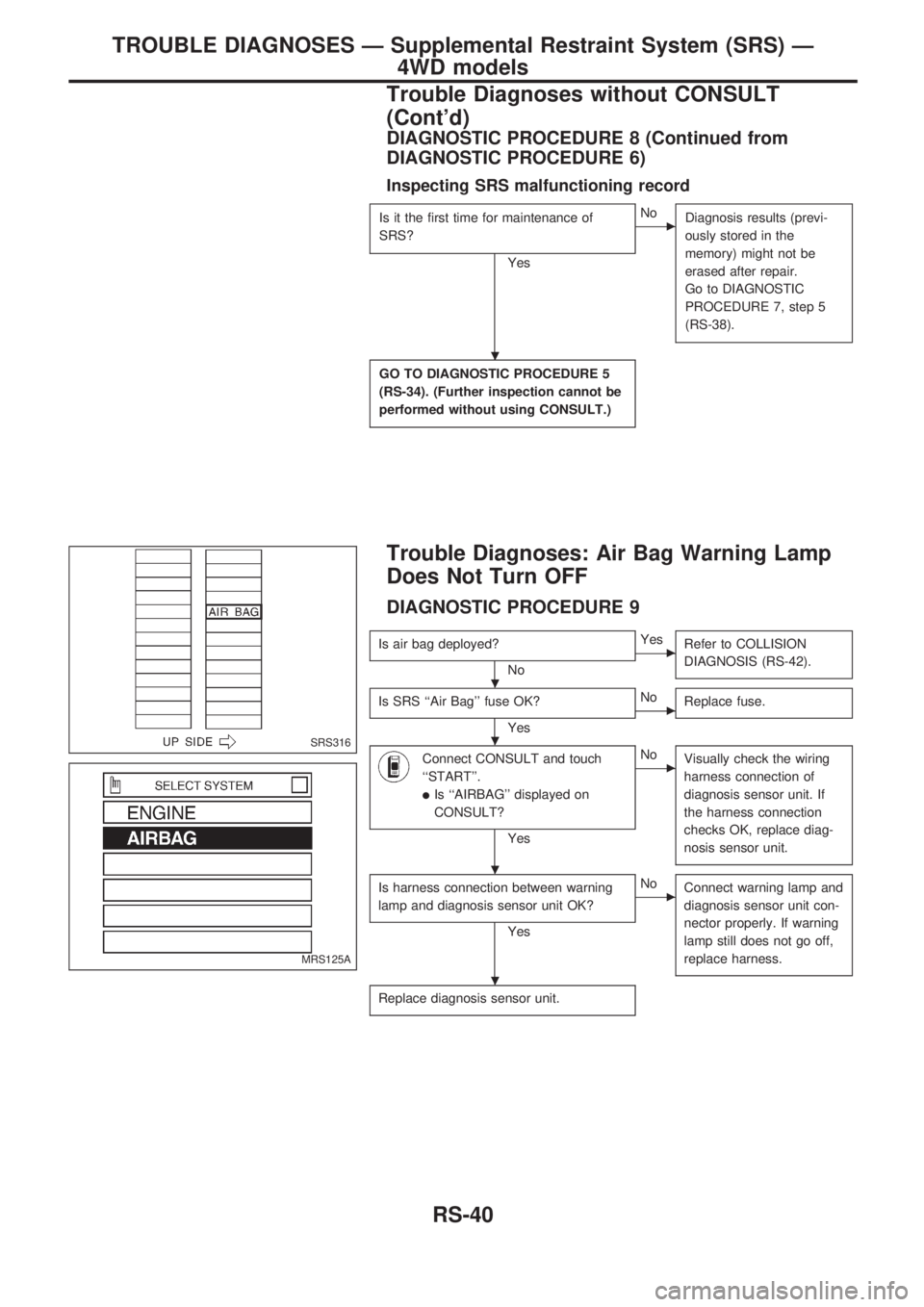
DIAGNOSTIC PROCEDURE 8 (Continued from
DIAGNOSTIC PROCEDURE 6)
Inspecting SRS malfunctioning record
Is it the first time for maintenance of
SRS?
Yes
cNo
Diagnosis results (previ-
ously stored in the
memory) might not be
erased after repair.
Go to DIAGNOSTIC
PROCEDURE 7, step 5
(RS-38).
GO TO DIAGNOSTIC PROCEDURE 5
(RS-34). (Further inspection cannot be
performed without using CONSULT.)
Trouble Diagnoses: Air Bag Warning Lamp
Does Not Turn OFF
DIAGNOSTIC PROCEDURE 9
Is air bag deployed?
No
cYes
Refer to COLLISION
DIAGNOSIS (RS-42).
Is SRS ``Air Bag'' fuse OK?
Yes
cNo
Replace fuse.
Connect CONSULT and touch
``START''.
lIs ``AIRBAG'' displayed on
CONSULT?
Yes
cNo
Visually check the wiring
harness connection of
diagnosis sensor unit. If
the harness connection
checks OK, replace diag-
nosis sensor unit.
Is harness connection between warning
lamp and diagnosis sensor unit OK?
Yes
cNo
Connect warning lamp and
diagnosis sensor unit con-
nector properly. If warning
lamp still does not go off,
replace harness.
Replace diagnosis sensor unit.
SRS316
MRS125A
.
.
.
.
.
TROUBLE DIAGNOSES Ð Supplemental Restraint System (SRS) Ð
4WD models
Trouble Diagnoses without CONSULT
(Cont'd)
RS-40
Page 1212 of 1659
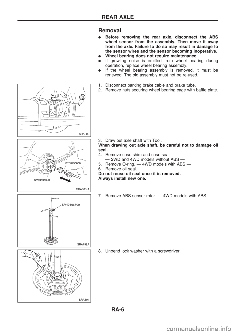
Removal
lBefore removing the rear axle, disconnect the ABS
wheel sensor from the assembly. Then move it away
from the axle. Failure to do so may result in damage to
the sensor wires and the sensor becoming inoperative.
lWheel bearing does not require maintenance.
lIf growling noise is emitted from wheel bearing during
operation, replace wheel bearing assembly.
lIf the wheel bearing assembly is removed, it must be
renewed. The old assembly must not be re-used.
1. Disconnect parking brake cable and brake tube.
2. Remove nuts securing wheel bearing cage with baffle plate.
3. Draw out axle shaft with Tool.
When drawing out axle shaft, be careful not to damage oil
seal.
4. Remove case shim and case seal.
Ð 2WD and 4WD models without ABS Ð
5. Remove O-ring. Ð 4WD models with ABS Ð
6. Remove oil seal.
Do not reuse oil seal once it is removed.
Always install new one.
7. Remove ABS sensor rotor. Ð 4WD models with ABS Ð
8. Unbend lock washer with a screwdriver.
SRA002
SRA003-A
SRA799A
SRA104
REAR AXLE
RA-6
Page 1223 of 1659
Supplemental Restraint System (SRS) ``AIR
BAG'' (4WD models)
The Supplemental Restraint System ``Air Bag'', used along with a seat belt, helps to reduce the risk or
severity of injury to the driver in a frontal collision. The Supplemental Restraint System consists of an air
bag module (located in the center of the steering wheel), a diagnosis sensor unit, warning lamp, wiring har-
ness and spiral cable. Information necessary to service the system safely is included in theRS sectionof
this Service Manual.
WARNING:
lTo avoid rendering the SRS inoperative, which could increase the risk of personal injury or death
in the event of a collision which would result in air bag inflation, all maintenance must be per-
formed by an authorized NISSAN dealer.
lImproper maintenance, including incorrect removal and installation of the SRS, can lead to per-
sonal injury caused by unintentional activation of the system.
lDo not use electrical test equipment on any circuit related to the SRS unless instructed to in this
Service Manual. SRS wiring harnesses are covered with yellow insulation either just before the
harness connectors or for the complete harness, for easy identification.
Supplemental Restraint System (SRS) ``AIR
BAG'' (2WD models)
The Supplemental Restraint System ``Air Bag'', used along with a seat belt, helps to reduce the risk or
severity of injury to the driver in a frontal collision. The Supplemental Restraint System consists of an air
bag module (located in the center of the steering wheel), a diagnosis sensor unit, warning lamp and spiral
cable. Information necessary to service the system safely is included in theRS sectionof this Service
Manual.
WARNING:
lTo avoid rendering the SRS inoperative, which could increase the risk of personal injury or death
in the event of a collision which would result in air bag inflation, all maintenance must be per-
formed by an authorized NISSAN dealer.
lImproper maintenance, including incorrect removal and installation of the SRS, can lead to per-
sonal injury caused by unintentional activation of the system.
lDo not use electrical test equipment on any circuit related to the SRS.
Precautions for Steering System
lBefore disassembly, thoroughly clean the outside of the unit.
lDisassembly should be done in a clean work area. It is important to prevent the internal parts
from becoming contaminated by dirt or other foreign matter.
lFor easier and proper assembly, place disassembled parts in order on a parts rack.
lUse nylon cloths or paper towels to clean the parts; common shop rags can leave lint that might
interfere with their operation.
lBefore inspection or reassembly, carefully clean all parts with a general purpose, non-flammable
solvent.
lBefore assembly, apply a coat of recommended ATF* to hydraulic parts. Petroleum jelly may be
applied to O-rings and seals. Do not use any grease.
lReplace all gaskets, seals and O-rings. Avoid damaging O-rings, seals and gaskets during instal-
lation. Perform functional tests whenever designated.
*: Automatic Transmission Fluid type DEXRON
TMII E, DEXRONTMIII, or equivalent.
PRECAUTIONS AND PREPARATION
ST-1
Page 1299 of 1659
Supplemental Restraint System (SRS) ``AIR
BAG'' (4WD models)
The Supplemental Restraint System ``AIR BAG'', used along with a seat belt, helps to reduce the risk or
severity of injury to the driver in a frontal collision. The Supplemental Restraint System consists of an air
bag module (located in the center of the steering wheel), a diagnosis sensor unit, warning lamp, wiring har-
ness and spiral cable. Information necessary to service the system safely is included in theRS sectionof
this Service Manual.
WARNING:
lTo avoid rendering the SRS inoperative, which could increase the risk of personal injury or death
in the event of a collision which would result in air bag inflation, all maintenance must be per-
formed by an authorized NISSAN dealer.
lImproper maintenance, including incorrect removal and installation of the SRS, can lead to per-
sonal injury caused by unintentional activation of the system.
lDo not use electrical test equipment on any circuit related to the SRS unless instructed to in this
Service Manual. SRS wiring harnesses are covered with yellow insulation either just before the
harness connectors or for the complete harness, for easy identification.
Supplemental Restraint System (SRS) ``AIR
BAG'' (2WD models)
The Supplemental Restraint System ``AIR BAG'', used along with a seat belt, helps to reduce the risk or
severity of injury to the driver in a frontal collision. The Supplemental Restraint System consists of an air
bag module (located in the center of the steering wheel), a diagnosis sensor unit, warning lamp and spiral
cable. Information necessary to service the system safely is included in theRS sectionof this Service
Manual.
WARNING:
lTo avoid rendering the SRS inoperative, which could increase the risk of personal injury or death
in the event of a collision which would result in air bag inflation, all maintenance must be per-
formed by an authorized NISSAN dealer.
lImproper maintenance, including incorrect removal and installation of the SRS, can lead to per-
sonal injury caused by unintentional activation of the system.
lDo not use electrical test equipment on any circuit related to the SRS.
PRECAUTIONS
EL-1
Page 1316 of 1659
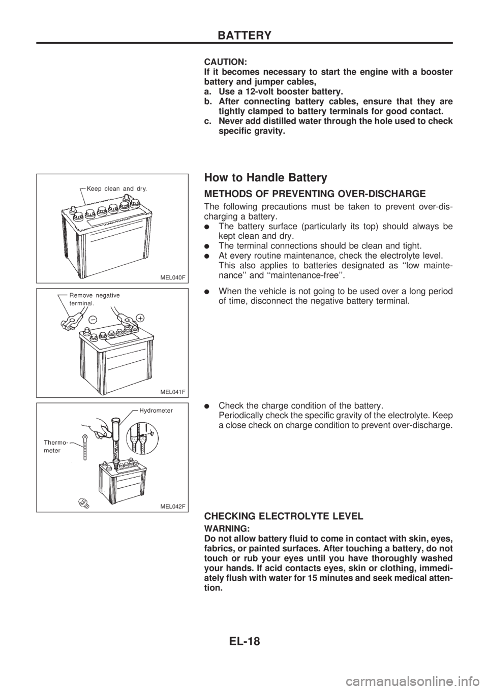
CAUTION:
If it becomes necessary to start the engine with a booster
battery and jumper cables,
a. Use a 12-volt booster battery.
b. After connecting battery cables, ensure that they are
tightly clamped to battery terminals for good contact.
c. Never add distilled water through the hole used to check
specific gravity.
How to Handle Battery
METHODS OF PREVENTING OVER-DISCHARGE
The following precautions must be taken to prevent over-dis-
charging a battery.
lThe battery surface (particularly its top) should always be
kept clean and dry.
lThe terminal connections should be clean and tight.
lAt every routine maintenance, check the electrolyte level.
This also applies to batteries designated as ``low mainte-
nance'' and ``maintenance-free''.
lWhen the vehicle is not going to be used over a long period
of time, disconnect the negative battery terminal.
lCheck the charge condition of the battery.
Periodically check the specific gravity of the electrolyte. Keep
a close check on charge condition to prevent over-discharge.
CHECKING ELECTROLYTE LEVEL
WARNING:
Do not allow battery fluid to come in contact with skin, eyes,
fabrics, or painted surfaces. After touching a battery, do not
touch or rub your eyes until you have thoroughly washed
your hands. If acid contacts eyes, skin or clothing, immedi-
ately flush with water for 15 minutes and seek medical atten-
tion.
MEL040F
MEL041F
MEL042F
BATTERY
EL-18
Page 1617 of 1659
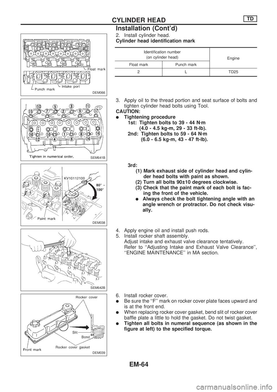
2. Install cylinder head.
Cylinder head identification mark
Identification number
(on cylinder head)
Engine
Float mark Punch mark
2 L TD25
3. Apply oil to the thread portion and seat surface of bolts and
tighten cylinder head bolts using Tool.
CAUTION:
lTightening procedure
1st: Tighten bolts to 39 - 44 Nzm
(4.0 - 4.5 kg-m, 29 - 33 ft-lb).
2nd: Tighten bolts to 59 - 64 Nzm
(6.0 - 6.5 kg-m, 43 - 47 ft-lb).
3rd:
(1) Mark exhaust side of cylinder head and cylin-
der head bolts with paint as shown.
(2) Turn all bolts 90 10 degrees clockwise.
(3) Check that the paint mark of each bolt is fac-
ing the front of the vehicle.
lAlways check the bolt tightening angle with an
angle wrench or protractor. Do not check visu-
ally.
4. Apply engine oil and install push rods.
5. Install rocker shaft assembly.
Adjust intake and exhaust valve clearance tentatively.
Refer to ``Adjusting Intake and Exhaust Valve Clearance'',
``ENGINE MAINTENANCE'' in MA section.
6. Install rocker cover.
lBe sure the ``F'' mark on rocker cover plate faces upward and
is at the front end.
lWhen replacing rocker cover gasket, bend slit of rocker cover
baffle plate a little to hold the gasket. Do not twist gasket.
lTighten all bolts in numeral sequence (as shown in the
figure at left) to the specified torque.
DEM066
SEM641B
DEM038
SEM642B
DEM039
CYLINDER HEADTD
Installation (Cont'd)
EM-64