Page 1012 of 1659
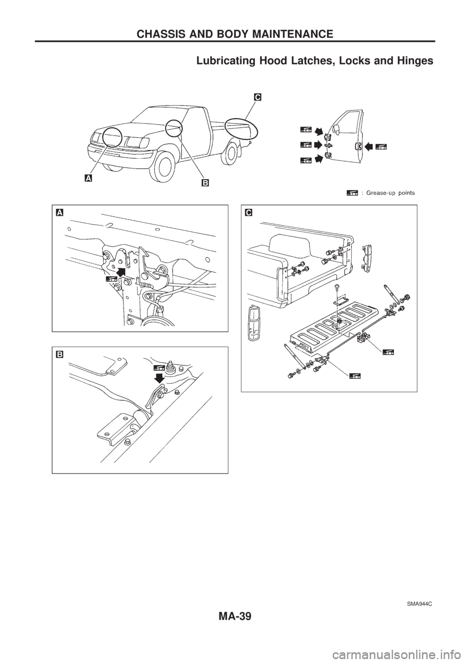
Lubricating Hood Latches, Locks and Hinges
SMA944C
CHASSIS AND BODY MAINTENANCE
MA-39
Page 1013 of 1659
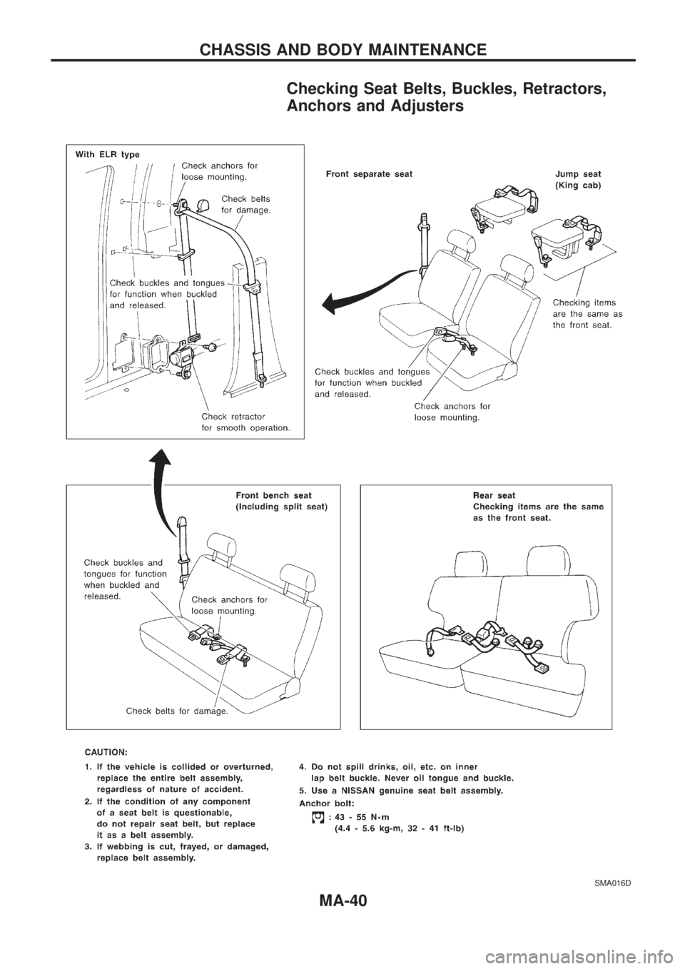
Checking Seat Belts, Buckles, Retractors,
Anchors and Adjusters
SMA016D
CHASSIS AND BODY MAINTENANCE
MA-40
Page 1014 of 1659
Checking Body Corrosion
Visually check the body sheet metal panel for corrosion, paint damage (scratches, chipping, rubbing, etc.)
or damage to the anti-corrosion materials. In particular, check the following locations.
Hemmed portion
Hood front end, door lower end, trunk lid rear end, etc.
Panel joint
Side sill of rear fender and center pillar, rear wheel housing of rear fender, around strut tower in engine
compartment, etc.
Panel edge
Trunk lid opening, sunroof opening, fender wheelarch flange, fuel filler lid flange, around holes in panel, etc.
Parts contact
Waist molding, windshield molding, bumper, etc.
Protectors
Damage or condition of mudguard, fender protector, chipping protector, etc.
Anti-corrosion materials
Damage or separation of anti-corrosion materials under the body.
Drain holes
Condition of drain holes at door and side sill.
When repairing corroded areas, refer to the Corrosion Repair Manual.
CHASSIS AND BODY MAINTENANCE
MA-41
Page 1015 of 1659
Engine Maintenance (KA)
INSPECTION AND ADJUSTMENT
Drive belt deflection
Unit: mm (in)
Used belt deflection
Deflection of
new belt
LimitDeflection after
adjustment
Alternator 17 (0.67)10-12
(0.39 - 0.47)8-10
(0.31 - 0.39)
Air conditioner
compressor16 (0.63)10-12
(0.39 - 0.47)8-10
(0.31 - 0.39)
Power steering
oil pump15 (0.59)9-11
(0.35 - 0.43)7-9
(0.28 - 0.35)
Applied pushing
force98 N (10 kg, 22 lb)
Spark plug
Standard type ZFR5E-11
Hot type ZFR4E-11
Cold type ZFR6E-11
Plug gap mm (in) 1.0 - 1.1 (0.039 - 0.043)
Ignition wire
Resistance kW/m (kW/ft) Less than 12.2 (3.72)
Engine Maintenance (TD)
INSPECTION AND ADJUSTMENT
Drive belt deflection
Unit: mm (in)
Used belt deflection
Deflection of
new belt
LimitDeflection after
adjustment
Alternator20
(0.79)11-13
(0.43 - 0.51)9-11
(0.35 - 0.43)
Air conditioner
compressor12
(0.47)6 - 7.5
(0.236 - 0.295)5 - 6.5
(0.197 - 0.256)
Power steering
oil pump15
(0.59)8 - 9.5
(0.315 - 0.374)7 - 8.5
(0.276 - 0.335)
Applied pushing
force98 N (10 kg, 22 lb)
Inspect drive belt deflections when engine is cold.
Valve clearance (Hot)
Intake and exhaust mm (in) 0.30 - 0.40 (0.012 - 0.016)
Injection nozzle
Injection pressure
kPa (bar, kg/cm2, psi)
Used nozzle9,807 - 10,297
(98.1 - 103.0, 100 - 105,
1,422 - 1,493)
New nozzle10,297 - 11,278
(103.0 - 112.8, 105 - 115,
1,493 - 1,635)
Idle speed
FICD OFF FICD ON
Idle speed rpm
TD25 700 50 850 50
Chassis and Body Maintenance
INSPECTION AND ADJUSTMENT
Wheel balance
Maximum allowable
unbalanceDynamic
(At rim flange)
g (oz)10 (0.35) (one side)
Static g (oz) 20 (0.71)
SERVICE DATA AND SPECIFICATIONS (SDS)
MA-42
Page 1163 of 1659
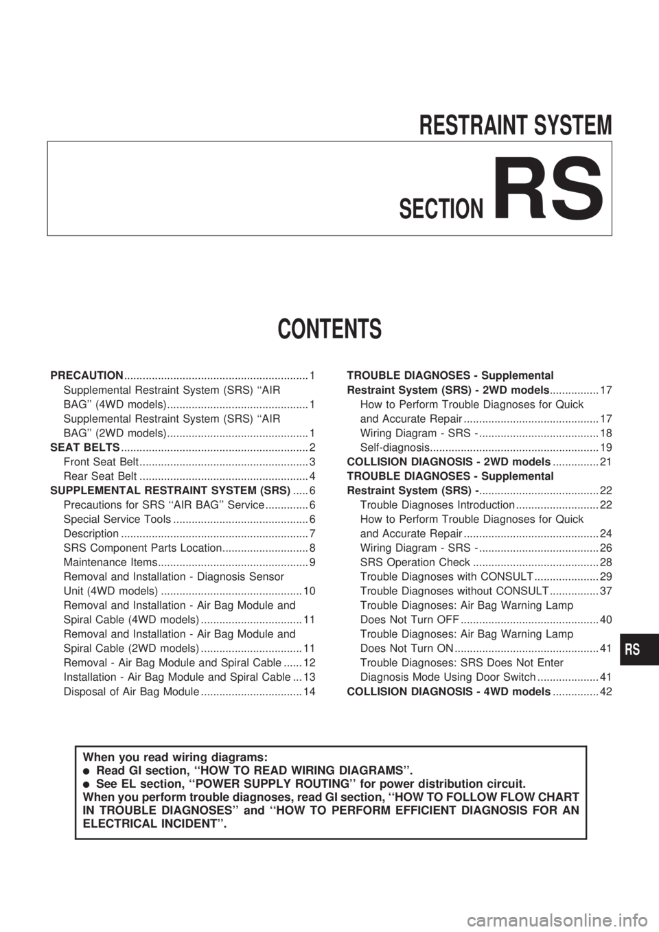
RESTRAINT SYSTEM
SECTION
RS
CONTENTS
PRECAUTION............................................................ 1
Supplemental Restraint System (SRS) ``AIR
BAG'' (4WD models).............................................. 1
Supplemental Restraint System (SRS) ``AIR
BAG'' (2WD models).............................................. 1
SEAT BELTS............................................................. 2
Front Seat Belt ....................................................... 3
Rear Seat Belt ....................................................... 4
SUPPLEMENTAL RESTRAINT SYSTEM (SRS)..... 6
Precautions for SRS ``AIR BAG'' Service .............. 6
Special Service Tools ............................................ 6
Description ............................................................. 7
SRS Component Parts Location............................ 8
Maintenance Items................................................. 9
Removal and Installation - Diagnosis Sensor
Unit (4WD models) .............................................. 10
Removal and Installation - Air Bag Module and
Spiral Cable (4WD models) ................................. 11
Removal and Installation - Air Bag Module and
Spiral Cable (2WD models) ................................. 11
Removal - Air Bag Module and Spiral Cable ...... 12
Installation - Air Bag Module and Spiral Cable ... 13
Disposal of Air Bag Module ................................. 14TROUBLE DIAGNOSES - Supplemental
Restraint System (SRS) - 2WD models................ 17
How to Perform Trouble Diagnoses for Quick
and Accurate Repair ............................................ 17
Wiring Diagram - SRS - ....................................... 18
Self-diagnosis....................................................... 19
COLLISION DIAGNOSIS - 2WD models............... 21
TROUBLE DIAGNOSES - Supplemental
Restraint System (SRS) -....................................... 22
Trouble Diagnoses Introduction ........................... 22
How to Perform Trouble Diagnoses for Quick
and Accurate Repair ............................................ 24
Wiring Diagram - SRS - ....................................... 26
SRS Operation Check ......................................... 28
Trouble Diagnoses with CONSULT ..................... 29
Trouble Diagnoses without CONSULT ................ 37
Trouble Diagnoses: Air Bag Warning Lamp
Does Not Turn OFF ............................................. 40
Trouble Diagnoses: Air Bag Warning Lamp
Does Not Turn ON ............................................... 41
Trouble Diagnoses: SRS Does Not Enter
Diagnosis Mode Using Door Switch .................... 41
COLLISION DIAGNOSIS - 4WD models............... 42
When you read wiring diagrams:
lRead GI section, ``HOW TO READ WIRING DIAGRAMS''.
lSee EL section, ``POWER SUPPLY ROUTING'' for power distribution circuit.
When you perform trouble diagnoses, read GI section, ``HOW TO FOLLOW FLOW CHART
IN TROUBLE DIAGNOSES'' and ``HOW TO PERFORM EFFICIENT DIAGNOSIS FOR AN
ELECTRICAL INCIDENT''.
RS
Page 1164 of 1659
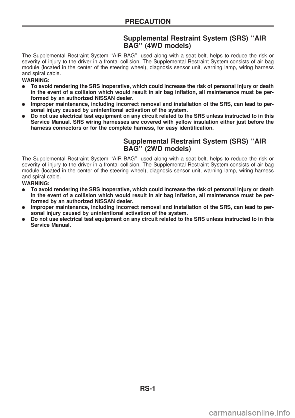
Supplemental Restraint System (SRS) ``AIR
BAG'' (4WD models)
The Supplemental Restraint System ``AIR BAG'', used along with a seat belt, helps to reduce the risk or
severity of injury to the driver in a frontal collision. The Supplemental Restraint System consists of air bag
module (located in the center of the steering wheel), diagnosis sensor unit, warning lamp, wiring harness
and spiral cable.
WARNING:
lTo avoid rendering the SRS inoperative, which could increase the risk of personal injury or death
in the event of a collision which would result in air bag inflation, all maintenance must be per-
formed by an authorized NISSAN dealer.
lImproper maintenance, including incorrect removal and installation of the SRS, can lead to per-
sonal injury caused by unintentional activation of the system.
lDo not use electrical test equipment on any circuit related to the SRS unless instructed to in this
Service Manual. SRS wiring harnesses are covered with yellow insulation either just before the
harness connectors or for the complete harness, for easy identification.
Supplemental Restraint System (SRS) ``AIR
BAG'' (2WD models)
The Supplemental Restraint System ``AIR BAG'', used along with a seat belt, helps to reduce the risk or
severity of injury to the driver in a frontal collision. The Supplemental Restraint System consists of air bag
module (located in the center of the steering wheel), diagnosis sensor unit, warning lamp, wiring harness
and spiral cable.
WARNING:
lTo avoid rendering the SRS inoperative, which could increase the risk of personal injury or death
in the event of a collision which would result in air bag inflation, all maintenance must be per-
formed by an authorized NISSAN dealer.
lImproper maintenance, including incorrect removal and installation of the SRS, can lead to per-
sonal injury caused by unintentional activation of the system.
lDo not use electrical test equipment on any circuit related to the SRS unless instructed to in this
Service Manual.
PRECAUTION
RS-1
Page 1172 of 1659
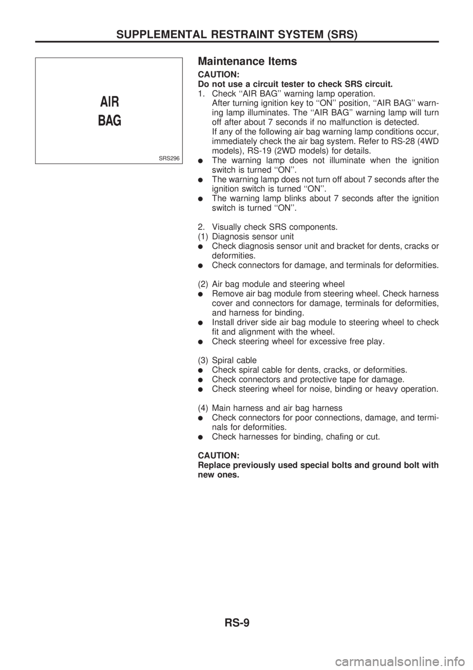
Maintenance Items
CAUTION:
Do not use a circuit tester to check SRS circuit.
1. Check ``AIR BAG'' warning lamp operation.
After turning ignition key to ``ON'' position, ``AIR BAG'' warn-
ing lamp illuminates. The ``AIR BAG'' warning lamp will turn
off after about 7 seconds if no malfunction is detected.
If any of the following air bag warning lamp conditions occur,
immediately check the air bag system. Refer to RS-28 (4WD
models), RS-19 (2WD models) for details.
lThe warning lamp does not illuminate when the ignition
switch is turned ``ON''.
lThe warning lamp does not turn off about 7 seconds after the
ignition switch is turned ``ON''.
lThe warning lamp blinks about 7 seconds after the ignition
switch is turned ``ON''.
2. Visually check SRS components.
(1) Diagnosis sensor unit
lCheck diagnosis sensor unit and bracket for dents, cracks or
deformities.
lCheck connectors for damage, and terminals for deformities.
(2) Air bag module and steering wheel
lRemove air bag module from steering wheel. Check harness
cover and connectors for damage, terminals for deformities,
and harness for binding.
lInstall driver side air bag module to steering wheel to check
fit and alignment with the wheel.
lCheck steering wheel for excessive free play.
(3) Spiral cable
lCheck spiral cable for dents, cracks, or deformities.
lCheck connectors and protective tape for damage.
lCheck steering wheel for noise, binding or heavy operation.
(4) Main harness and air bag harness
lCheck connectors for poor connections, damage, and termi-
nals for deformities.
lCheck harnesses for binding, chafing or cut.
CAUTION:
Replace previously used special bolts and ground bolt with
new ones.
SRS296
SUPPLEMENTAL RESTRAINT SYSTEM (SRS)
RS-9
Page 1180 of 1659
How to Perform Trouble Diagnoses for Quick
and Accurate Repair
A good understanding of the malfunction conditions can make troubleshooting faster and more accurate.
In general, each customer feels differently about a problem. It is important to fully understand the symptoms
or conditions for a customer complaint.
INFORMATION FROM CUSTOMER
WHAT ........ Vehicle model
WHEN ....... Date, Frequencies
WHERE ..... Road conditions
HOW .......... Operating conditions, Symptoms
PRELIMINARY CHECK
Check that the following parts are in good order.
lBattery [Refer to MA section (``GENERAL MAINTENANCE'').]
lFuse [Refer to EL section (``Fuse'', ``POWER SUPPLY ROUTING'').]
lSystem component-to-harness connections
DIAGNOSIS FUNCTION
The SRS self-diagnosis results can be read by using ``AIR BAG'' warning lamp.
Note: CONSULT cannot be used for trouble diagnoses.
CAUTION:
lDo not use a circuit tester to check SRS harness connectors unless instructed to in this Service
Manual.
lDo not attempt to repair, splice or modify the SRS wiring harness. If the harness is damaged,
replace it with a new one.
lKeep ground portion clean.
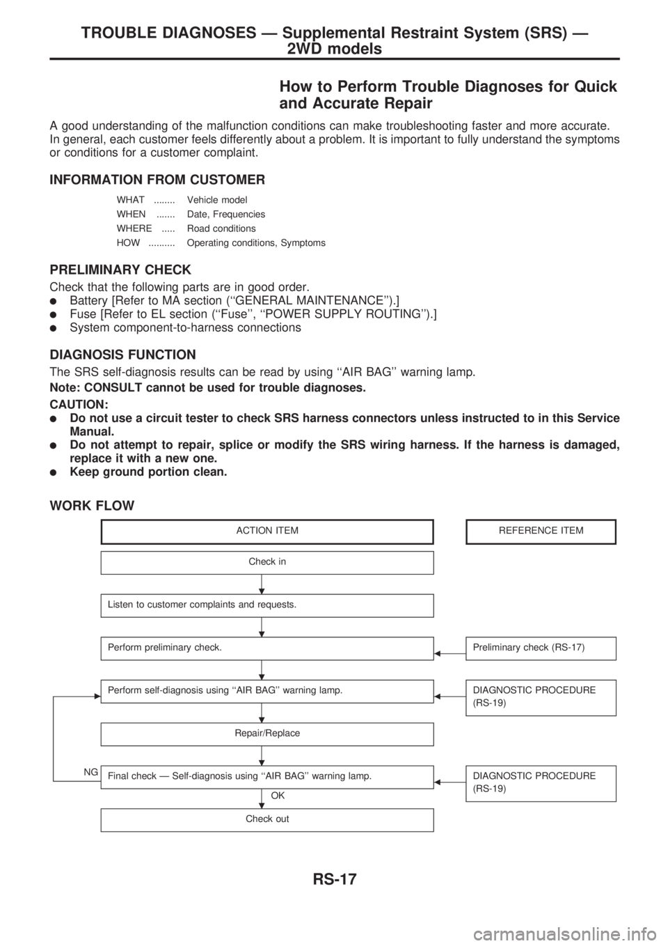
WORK FLOW
ACTION ITEMREFERENCE ITEM
Check in
Listen to customer complaints and requests.
Perform preliminary check.bPreliminary check (RS-17)
cPerform self-diagnosis using ``AIR BAG'' warning lamp.bDIAGNOSTIC PROCEDURE
(RS-19)
Repair/Replace
NGFinal check Ð Self-diagnosis using ``AIR BAG'' warning lamp.
OK
bDIAGNOSTIC PROCEDURE
(RS-19)
Check out
.
.
.
.
.
.
TROUBLE DIAGNOSES Ð Supplemental Restraint System (SRS) Ð
2WD models
RS-17