Page 1444 of 2490
Installation
8. Release the connector guide bush from the transmission case.
Release the (center) retaining bolt; remains captive in the
guide bush.
9. Remove the guide bush from the transmission casing.
Very carefully, pry the guid e bush from the transmission
casing using a screwdriver ag ainst the cast lug on the
casing.
10. Remove and discard the sealing rings.
Note the position and size of each ring.
1. Installation is the re verse of the removal procedure, noting the
following:
2. Clean all mating faces and relevant parts.
3. Lubricate the new sealing rings using clean transmission fluid.
Page 1450 of 2490

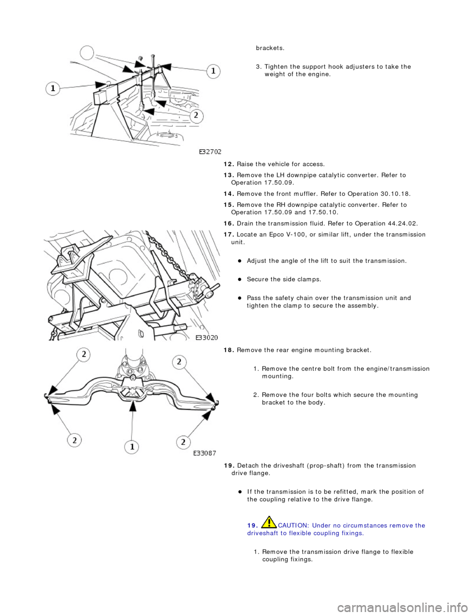
brackets.
3. Tighten the support hook adjusters to take the weight of the engine.
12. Raise the vehicle for access.
13. Remove the LH downpipe catalytic converter. Refer to
Operation 17.50.09.
14. Remove the front muffler. Re fer to Operation 30.10.18.
15. Remove the RH downpipe catalytic converter. Refer to
Operation 17.50.09 and 17.50.10.
16. Drain the transmission fluid. Refer to Operation 44.24.02.
17. Locate an Epco V-100, or sim ilar lift, under the transmission
unit.
Adjust the angle of the lift to suit the transmission.
Secure the side clamps.
Pass the safety chain over the transmission unit and
tighten the clamp to secure the assembly.
18. Remove the rear engine mounting bracket.
1. Remove the centre bolt from the engine/transmission
mounting.
2. Remove the four bolts which secure the mounting
bracket to the body.
19. Detach the driveshaft (prop- shaft) from the transmission
drive flange.
If the transmission is to be refitted, mark the position of
the coupling relative to the drive flange.
19. CAUTION: Under no circ umstances remove the
driveshaft to flexible coupling fixings.
1. Remove the transmission drive flange to flexible
coupling fixings.
Page 1451 of 2490
20. Lower the transmission unit.
21. Detach the gear selector cable from the transmission unit.
1. Remove the selector cable ball pin to selector lever nut.
2. Lower the transmissi on lift for access.
3. Remove the selector cable to transmission casing bolts.
22. Release the transmission ha rness multiplug bracket.
1. Remove the two bolts which secure the bracket to the
transmission case, noting that one bolt also retains
the dipstick tube.
23. Disconnect the fluid cooler upper pipe.
Remove the bolt which secures the pipe to the cylinder
block and remove the bracket.
Remove the 'banjo' bolt.
Page 1452 of 2490
Discard the Dowty seals.
Fit blanking plugs to the pipe and transmission.
24. Disconnect the fluid cooler lower pipe.
Remove the 'banjo' bolt.
Discard the Dowty seals.
Fit blanking plugs to the pipe and transmission.
25. Remove the three bolts which se cure the torque converter to
the drive plate.
1. Remove the access cover.
2. Rotate the crankshaft for access to each bolt and hold
to prevent movement. Remove each bolt.
26. Remove the LH and RH cataly st mounting brackets from the
transmission case.
Remove the two bolts from each side.
27. On the RH side, clear the cooler pipe for access.
28. NOTE: Viewed from the rear of the vehicle.
Remove the two upper bolts, as indicated, transmission to
engine.
Page 1456 of 2490

Automatic Transmission/Transaxle - 4.0L SC V8 - AJ26 - Input Shaft Seal
Disassembly and Assembly of Subassemblies
Special Tool(s)
Oil seal replacer
307-378
1. Disconnect the battery ground lead.
2. Remove the air intake / MAFM assembly, refer to Operation
19.10.30.
3. Raise the vehicle for access.
4. Remove the front muffler, 30.10.18
5. Remove the RH and LH catalytic converters, refer to Operation
17.50.09 and 17.50.10.
6. Drain the transmission fluid, refer to Operation 44.24.02.
7. Remove the transmission unit, refer to Operation 44.20.01.
8. Remove the torque converter fro m the transmission unit, refer
to Operation 44.17.07.
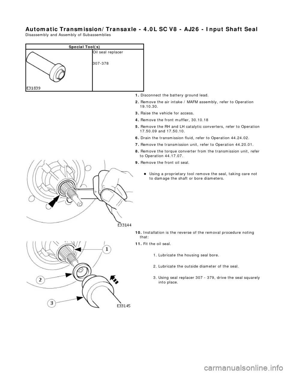
9. Remove the front oil seal.
Using a proprietary tool remove the seal, taking care not
to damage the shaft or bore diameters.
10. Installation is the reverse of the removal procedure noting
that:
11. Fit the oil seal.
1. Lubricate the housing seal bore.
2. Lubricate the outside diameter of the seal.
3. Using seal replacer 307 - 379, drive the seal squarely into place.
Page 1462 of 2490
Transmission/Transaxle Cooling - 4.0L NA V8 - AJ27/3.2L NA V8 - AJ26 -
Transmission Cooling
Description and Operation
The transmission fluid cooling system maintains fluid temperature within specified limits.
Parts List
Component Descriptions
The transmission fluid pipes:
Transfer fluid from the transmission to the cooler under the action of the hydraulic system pump. Return the cooled fluid from th e cooler to the transmission.
The transmission fluid cooler:
Is a plate type made from aluminum. Is mounted in the engi ne cooling radiator right-hand end tank.
Overheating Protection
If the engine coolant or transm ission fluid temperatures exceed their predefined limits, th e transmission control module locks
the torque converter clutch. By reducing slip, this minimises th e amount of heat transferred to the engine cooling system from
the transmission fluid.
ItemPart NumberDescription
1—Fluid pipe, oil FROM cooler
2—Fluid pipe, oil TO cooler
Page 1463 of 2490
Transmission/Transaxle Cooling - 4.0L SC V8 - AJ26 - Transmission
Cooling
Description and Operation
The transmission fluid cooling system maintains the fluid temperature within specified limits. The cooling element is located
in the engine cooling radiator LH end tank.
Fluid is circulated, under pressure, by the transmission pump to the cooler.
General Layout
Overheating Protection
If the engine coolant or transmission fluid temperatures exceed their predefined limits, the transmission control module
locks the torque converter clutch . By reducing slip, this minimises the amount of heat transferred to the engine cooling
system from the transmission fluid.
Page 1504 of 2490

Automatic Transmission/Transaxle External Controls - 4.0L SC V8 - AJ26 -
External Controls
Diagnosis and Testing
Problem Solving - Transmission Shift
Quick Reference Fault Chart
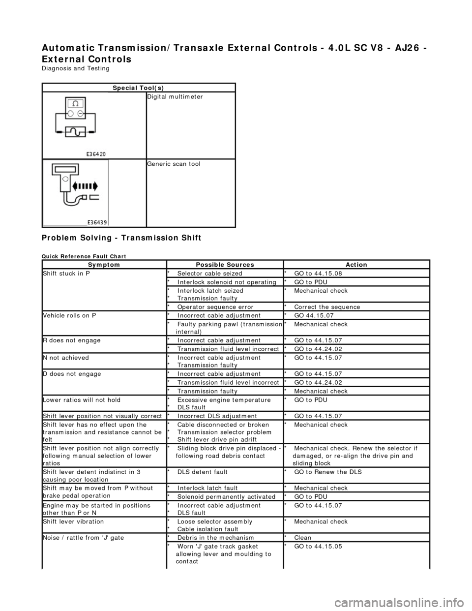
Special Tool(s)
Digital multimeter
Generic scan tool
SymptomPossible SourcesAction
Shift stuck in P Selector cable seized
*GO to 44.15.08
*
Interlock solenoid not operating
*GO to PDU
*
Interlock latch seized
Transmission faulty
*
*Mechanical check
*
Operator sequence error
*Correct the sequence
*
Vehicle rolls on P Incorrect cable adjustment
*GO 44.15.07
*
Faulty parking pawl (transmission internal)
*Mechanical check
*
R does not engageIncorrect cable adjustment
*GO to 44.15.07
*
Transmission fluid level incorrect
*GO to 44.24.02
*
N not achievedIncorrect cable adjustment
Transmission faulty
*
*GO to 44.15.07
*
D does not engageIncorrect cable adjustment *GO to 44.15.07
*
Transmission fluid level incorrect
*GO to 44.24.02
*
Transmission faulty
*Mechanical check
*
Lower ratios will not holdExcessive engine temperature
DLS fault
*
*GO to PDU
*
Shift lever position not visually correctIncorrect DLS adjustment
*GO to 44.15.07
*
Shift lever has no effect upon the
transmission and resistance cannot be
feltCable disconnected or broken
Transmission selector problem
Shift lever drive pin adrift
*
*
*Mechanical check
*
Shift lever position not align correctly
following manual selection of lower
ratiosSliding block drive pin displaced - following road debris contact
*Mechanical check. Renew the selector if
damaged, or re-align the drive pin and
sliding block
*
Shift lever detent indistinct in 3
causing poor locationDLS detent fault
*GO to Renew the DLS
*
Shift may be moved from P without
brake pedal operationInterlock latch fault
*Mechanical check
*
Solenoid permanently activated
*GO to PDU
*
Engine may be started in positions
other than P or N Incorrect cable adjustment
DLS fault
*
*GO to 44.15.07
*
Shift lever vibrationLoose selector assembly
Cable isolation fault
*
*Mechanical check
*
Noise / rattle from 'J' gateDebris in the mechanism
*Clean
*
Worn 'J' gate track gasket
allowing lever and moulding to
contact
*GO to 44.15.05
*