1998 JAGUAR X308 relay
[x] Cancel search: relayPage 1230 of 2490
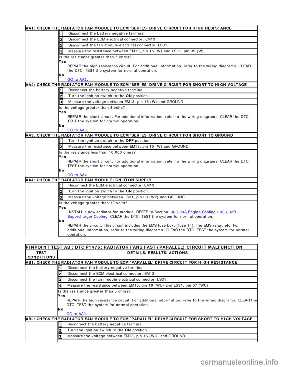
AA1: CHECK THE RA
DIATOR FAN MODULE TO ECM
'SERIES' DRIVE CIRCUIT FOR HIGH RESISTANCE
Disc
onnect the battery negative terminal.
1
D
i
sconnect the ECM electrical connector, EM13.
2
Disc
onne
ct the fan module electrical connector, LS31.
3
Meas
ure t
he resistance between EM13, pin 15 (W) and LS31, pin 09 (W).
4
Is th
e res
istance greater than 5 ohms?
Yes REPAIR the high resistance circui t. For additional information, refer to the wiring diagrams. CLEAR
the DTC. TEST the system for normal operation.
No GO to AA2
.
AA2: CHECK THE RA
DIATOR FAN MODULE TO ECM 'SER
IES' DRIVE CIRCUIT FOR SHORT TO HIGH VOLTAGE
Re
connect the battery negative terminal.
1
Turn the ignition swit
ch to the
ON position.
2
Measure t
he voltage between EM13, pin 15 (W) and GROUND.
3
Is the volt
age greater than 3 volts?
Yes REPAIR the short circuit. For addi tional information, refer to the wiring diagrams. CLEAR the DTC.
TEST the system for normal operation.
No GO to AA3
.
AA3: CHECK THE R A
DIATOR FAN MODULE TO ECM
'SERIES' DRIVE CIRCUIT FOR SHORT TO GROUND
Turn the ignition swit
ch to the
OFF position.
1
Meas ure t
he resistance between EM13, pin 15 (W) and GROUND.
2
Is
t
he resistance less than 10,000 ohms?
Yes
REPAIR the short circuit. For addi tional information, refer to the wiring diagrams. CLEAR the DTC.
TEST the system for normal operation.
No GO to AA4
.
AA4:
CHECK THE RADIATOR FAN MODULE IGNITION SUPPLY
Reconn
ect the ECM electrical connector, EM13.
1
Turn the ignition swit
ch to the
ON position.
2
Measure the voltage between LS 31,
pin 08 (WP) and GROUND.
3
Is the vol
t
age greater than 10 volts?
Yes INSTALL a new radiator fan module. REFER to Section 303
-03
A Engine Cooling
/
303-03B Supercharger Cooli
ng
. CLEA
R the DTC. TEST the sy stem f
or normal operation.
No REPAIR the circuit. This circui t includes the EMS fuse box, (f use 14), the EMS relay, etc. For
additional information, refer to the wiring diagrams. CLEAR the DT C. TEST the system for normal
operation.
PINPOINT TE ST
AB : DTC P1476; RADIATOR
FANS FAST (PARALLEL) CIRCUIT MALFUNCTION
TES
T
CONDITIONS
D E
TAILS/RESULTS/ACTIONS
AB1
:
CHECK THE RADIATOR FAN MODULE TO ECM
'PARALLEL' DRIVE CIRCUIT FOR HIGH RESISTANCE
Disc
onnect the battery negative terminal.
1
D
i
sconnect the ECM electrical connector, EM13.
2
Disc
onne
ct the fan module electrical connector, LS31.
3
Meas
ure t
he resistance between EM13, pin 16 (WU) and LS31, pin 07 (WU).
4
Is th
e res
istance greater than 5 ohms?
Yes REPAIR the high resistance circuit. For additional information, refer to the wiring diagrams. CLEAR the
DTC. TEST the system for normal operation.
No GO to AA2
.
AB2:
CHECK THE RADIATOR FAN MODULE TO ECM 'PARALLEL' DRIVE CIRCUIT FOR SHORT TO HIGH VOLTAGE
R
e
connect the battery negative terminal.
1
Turn the ignition swi
t
ch to the ON
position.
2
Measure t
he voltage between EM13, pin 16 (WU) and GROUND.
3
Page 1231 of 2490
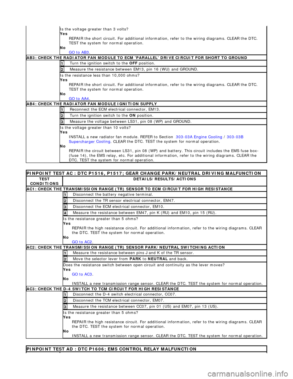
Is th
e voltage greater than 3 volts?
Yes REPAIR the short circuit. For addi tional information, refer to the wiring diagrams. CLEAR the DTC.
TEST the system for normal operation.
No GO to AB3
.
AB3
: CHECK THE RADIATOR FAN MODULE TO ECM
'PARALLEL' DRIVE CIRCUIT FOR SHORT TO GROUND
Turn the ignition swi
tch to the OFF
position.
1
Meas
ure the resistance between EM13, pin 16 (WU) and GROUND.
2
Is
the resistance less than 10,000 ohms?
Yes
REPAIR the short circuit. For addi tional information, refer to the wiring diagrams. CLEAR the DTC.
TEST the system for normal operation.
No GO to AA4
.
AB4
: CHECK THE RADIATOR FAN MODULE IGNITION SUPPLY
Re
connect the ECM electrical connector, EM13.
1
Turn the ignition swi
tch to the ON
position.
2
Measure the
voltage between LS
31, pin 08 (WP) and GROUND.
3
Is the vol
tage greater than 10 volts?
Yes INSTALL a new radiator fan module. REFER to Section 303
-0
3A Engine Cooling
/
30
3
-03
B
Supercharger
Cooling
. CLEA
R the DTC. TEST the sy
stem for normal operation.
No REPAIR the circuit between LS31, pin 08 (WP) and battery. This circuit includes the EMS fuse box-
(fuse 14), the EMS relay, etc. For additional information, refer to the wiring diagrams. CLEAR the
DTC. TEST the system for normal operation.
P
INPOINT TEST AC : DTC P1516, P1517; GEAR
CHANGE PARK/NEUTRAL DRIVING MALFUNCTION
TE
ST
CONDITIONS
D
ETAILS/RESULTS/ACTIONS
AC1: CH
ECK THE TRANSMISSION RANGE (TR) SE
NSOR TO ECM CIRCUIT FOR HIGH RESISTANCE
Di
sconnect the battery negative terminal.
1
Di
sconnect the TR sensor el
ectrical connector, EM47.
2
D
isconnect the ECM electrical connector, EM10.
3
Meas
ure the resistance between EM47, pin K (RU) and EM10, pin 15 (RU).
4
Is th
e resistance greater than 5 ohms?
Yes REPAIR the high resistance circui t. For additional information, refer to the wiring diagrams. CLEAR
the DTC. TEST the system for normal operation.
No GO to AC2
.
AC2: CH
ECK THE TRANSMISSION RANGE (TR)
SENSOR PARK/NEUTRAL SWITCHING ACTION
Meas
ure the resistance between pi
ns J and K of the TR sensor.
1
Mo
ve the selector lever from
PARK to NEUTRAL and back.
2
D
oes the resistance switch between open ci
rcuit and continuity as the lever moves?
Yes GO to AC3
.
No
INSTALL a new transmission range sensor. CLEAR th e DTC. TEST the system for normal operation.
AC3: CH
ECK THE D-4 SWITCH TO
TCM CIRCUIT FOR HIGH RESISTANCE
Di
sconnect the D-4 switch electrical connector, CC07.
1
Di
sconnect the TCM electrical connector, EM07.
2
Meas
ure the resistance between CC07,
pin 01 (US) and EM07, pin 13 (US).
3
Is th
e resistance greater than 5 ohms?
Yes REPAIR the high resistance circui t. For additional information, refer to the wiring diagrams. CLEAR
the DTC. TEST the system for normal operation.
No INSTALL a new transmission range sensor. CLEAR th e DTC. TEST the system for normal operation.
P
INPOINT TEST AD : DTC P1606;
EMS CONTROL RELAY MALFUNCTION
Page 1232 of 2490
TES
T
CONDITIONS
D E
TAILS/RESULTS/ACTIONS
AD1
:
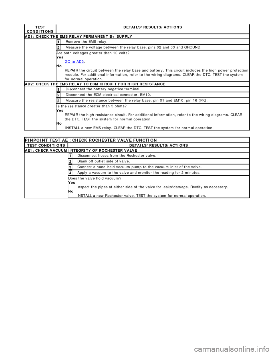
CHECK THE EMS RELAY PERMANENT B+ SUPPLY
R
e
move the EMS relay.
1
Meas
ure t
he voltage between the rela
y base, pins 02 and 03 and GROUND.
2
Are both vol
tages greater than 10 volts?
Yes GO to AD2
.
No
R
EPAIR the circuit between the rela
y base and battery. This circuit includes the high power protection
module. For additional information, refer to the wiring diagrams. CLEAR the DTC. TEST the system
for normal operation.
AD2 :
CHECK THE EMS RELAY TO ECM CIRCUIT FOR HIGH RESISTANCE
Di
sc
onnect the battery negative terminal.
1
D
i
sconnect the ECM electrical connector, EM10.
2
Meas
ure t
he resistance between the rela
y base, pin 01 and EM10, pin 16 (PK).
3
Is the res
istance greater than 5 ohms?
Yes REPAIR the high resistance circui t. For additional information, refer to the wiring diagrams. CLEAR
the DTC. TEST the system for normal operation.
No INSTALL a new EMS relay. CLEAR the DTC. TEST the system for normal operation.
PINPOINT TEST AE : CHECK
ROCHESTER VALVE FUNCTION
T
E
ST CONDITIONS
D
E
TAILS/RESULTS/ACTIONS
AE1: CHEC
K VAC
UUM INTEGRITY OF ROCHESTER VALVE
Di
sc
onnect hoses from the Rochester valve.
1
Bl
a
nk off outlet side of valve.
2
Con
n
ect a hand-held vacuum pump to the vacuum inlet of the valve.
3
Appl
y a vacuum t
o the valve and mo
nitor the reading for 2 minutes.
4
Do
es the valve hold vacuum?
Yes Inspect the pipes at either side of the valve for leaks/damage. Rectify as necessary.
No INSTALL a new Rochester valve. TEST the system for normal operation.
Page 1265 of 2490
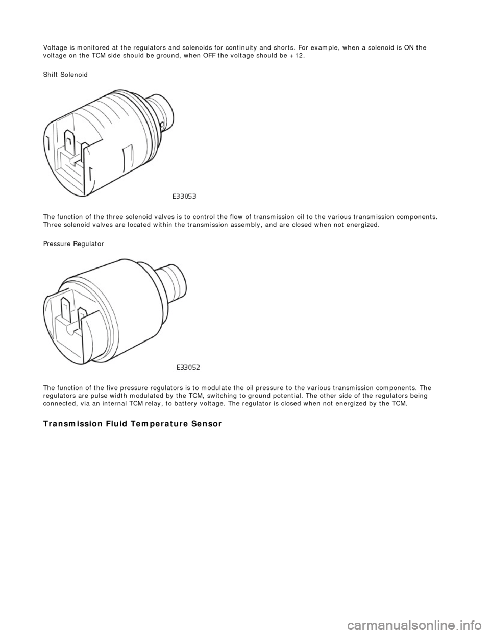
Voltage is monitored at the regulators and solenoids for continuity and shorts. For example, when a solenoid is ON the
voltage on the TCM side should be ground , when OFF the voltage should be +12.
Shift Solenoid
The function of the three soleno id valves is to control the flow of transmissi on oil to the various transmission components.
Three solenoid valves are located wi thin the transmission assembly, and are closed when not energized.
Pressure Regulator
The function of the five pressu re regulators is to modulate the oil pressure to the various transmission components. The
regulators are pulse width modulated by the TCM, switching to ground potential. The other side of the regulators being
connected, via an internal TCM relay, to battery voltage. The regulator is closed when not energized by the TCM.
Transmission Fluid Temperature Sensor
Page 1545 of 2490
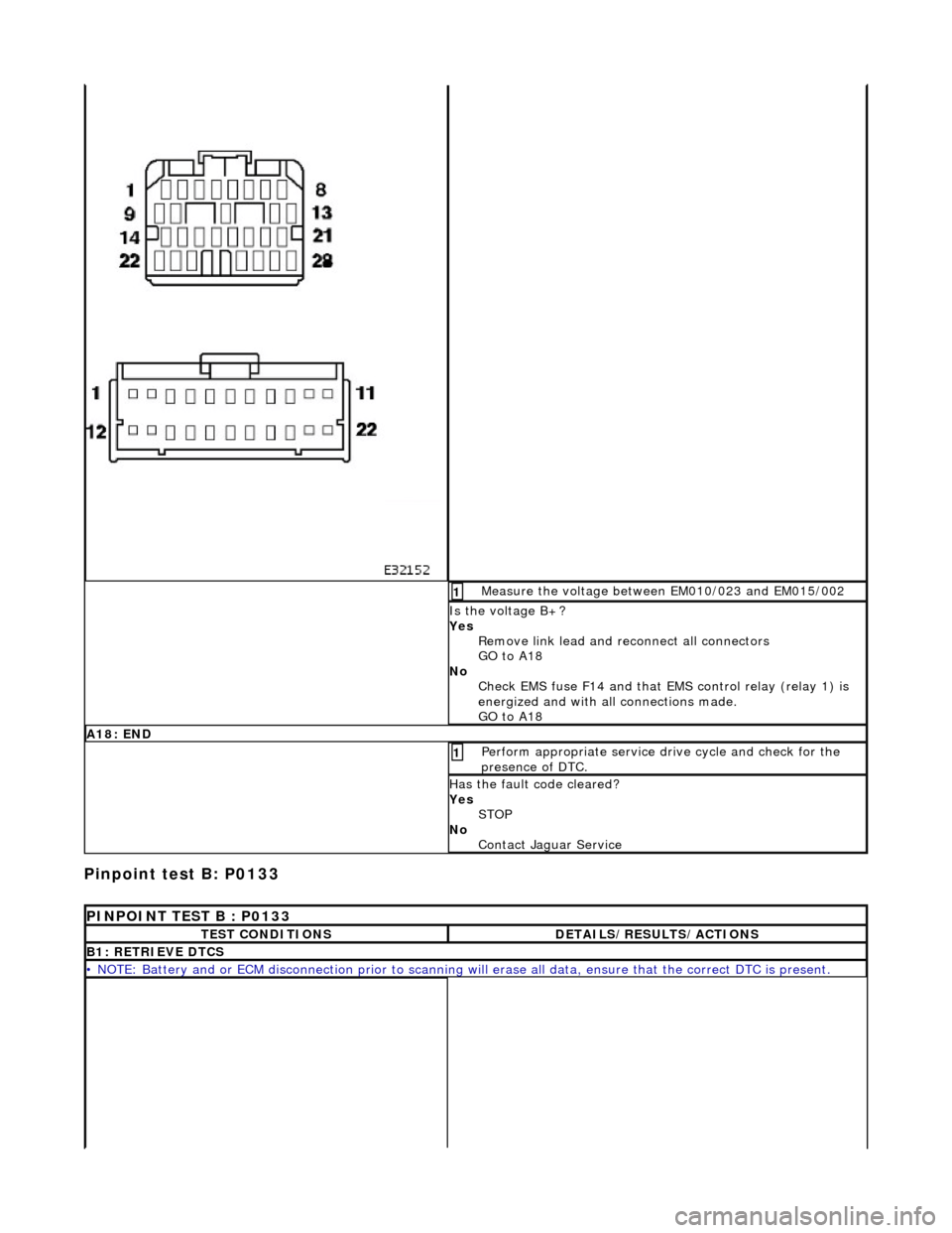
Pinpoint test B: P0133
Measure the voltage between EM010/023 and EM015/002 1
Is the voltage B+?
Yes Remove link lead and reconnect all connectors
GO to A18
No Check EMS fuse F14 and that EMS control relay (relay 1) is
energized and with all connections made.
GO to A18
A18: END
Perform appropriate service drive cycle and check for the
presence of DTC. 1
Has the fault code cleared?
Yes STOP
No Contact Jaguar Service
PINPOINT TEST B : P0133
TEST CONDITIONSDETAILS/RESULTS/ACTIONS
B1: RETRIEVE DTCS
• NOTE: Battery and or ECM disconnection prior to scanning wi ll erase all data, ensure that the correct DTC is present.
Page 1557 of 2490
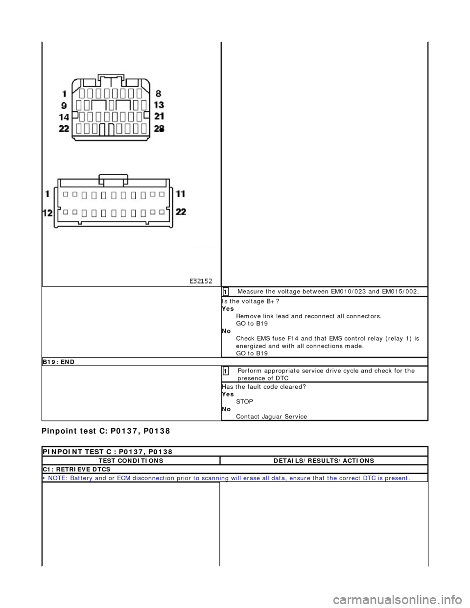
Pinpoint test C: P0137, P0138
Measure the voltage between EM010/023 and EM015/002. 1
Is the voltage B+?
Yes Remove link lead and reconnect all connectors.
GO to B19
No Check EMS fuse F14 and that EMS control relay (relay 1) is
energized and with all connections made.
GO to B19
B19: END
Perform appropriate service drive cycle and check for the
presence of DTC 1
Has the fault code cleared?
Yes STOP
No Contact Jaguar Service
PINPOINT TEST C : P0137, P0138
TEST CONDITIONSDETAILS/RESULTS/ACTIONS
C1: RETRIEVE DTCS
• NOTE: Battery and or ECM disconnection prior to scanning wi ll erase all data, ensure that the correct DTC is present.
Page 1597 of 2490
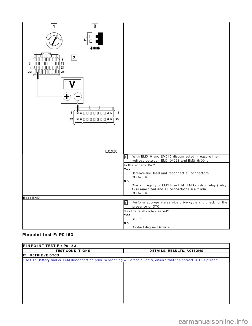
Pinpoint test F: P0153
With EM010 and EM015 disconnected, measure the
voltage between EM010/023 and EM015/001. 1
Is the voltage B+?
Yes Remove link lead and reconnect all connectors.
GO to E18
No Check integrity of EMS fuse F1 4, EMS control relay (relay
1) is energized and all connections are made.
GO to E18
E18: END
Perform appropriate service drive cycle and check for the
presence of DTC. 1
Has the fault code cleared?
Yes STOP
No Contact Jaguar Service
PINPOINT TEST F : P0153
TEST CONDITIONSDETAILS/RESULTS/ACTIONS
F1: RETRIEVE DTCS
• NOTE: Battery and or ECM disconnection prior to scanning wi ll erase all data, ensure that the correct DTC is present.
Page 1609 of 2490
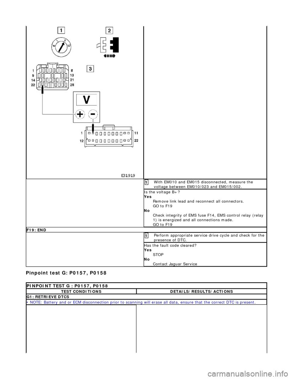
Pinpoint test G: P0157, P0158
With EM010 and EM015 disconnected, measure the
voltage between EM010/023 and EM015/002. 1
Is the voltage B+?
Yes Remove link lead and reconnect all connectors.
GO to F19
No Check integrity of EMS fuse F1 4, EMS control relay (relay
1) is energized and all connections made.
GO to F19
F19: END
Perform appropriate service drive cycle and check for the
presence of DTC. 1
Has the fault code cleared?
Yes STOP
No Contact Jaguar Service
PINPOINT TEST G : P0157, P0158
TEST CONDITIONSDETAILS/RESULTS/ACTIONS
G1: RETRIEVE DTCS
• NOTE: Battery and or ECM disconnection prior to scanning wi ll erase all data, ensure that the correct DTC is present.