Page 1800 of 2490
Compressor:
Features
Engine mounted, driven by the accessory drive belt. Fixed displacement type. High-pressure relief valve, to avoid system over-pressure. ECM controlled clutch energized via a relay.
Receiver drier:
Vertically mounted on the ri ght-hand side of the engine compartment next to the engine coolant radiator. Fitted with the high-side charge port. Includes a fluorescent tracer dye me chanism to aid leak detection.
ItemPart NumberDescription
1—Compressor assembly
2—Condenser
3—Evaporator and heater matrix (internal)
4—Receiver drier
5—4-level pressure switch
6—Expansion valve (internal)
7—High-side charge port
8—Low-side charge port
9—Suction muffler
10—Discharge hose
11—Discharge pipe
12—Suction hose
13—Suction pipe
14—Liquid line
15—Jumper hose (condenser hose)
Page 1831 of 2490

other sensors. This feature prevents the effects of sudden changes in air outlet temperatures due to factors such as:
Recirculating air from the engine cooling pack at low vehicle speeds Sudden changes in ambient temperature The effects of water splash
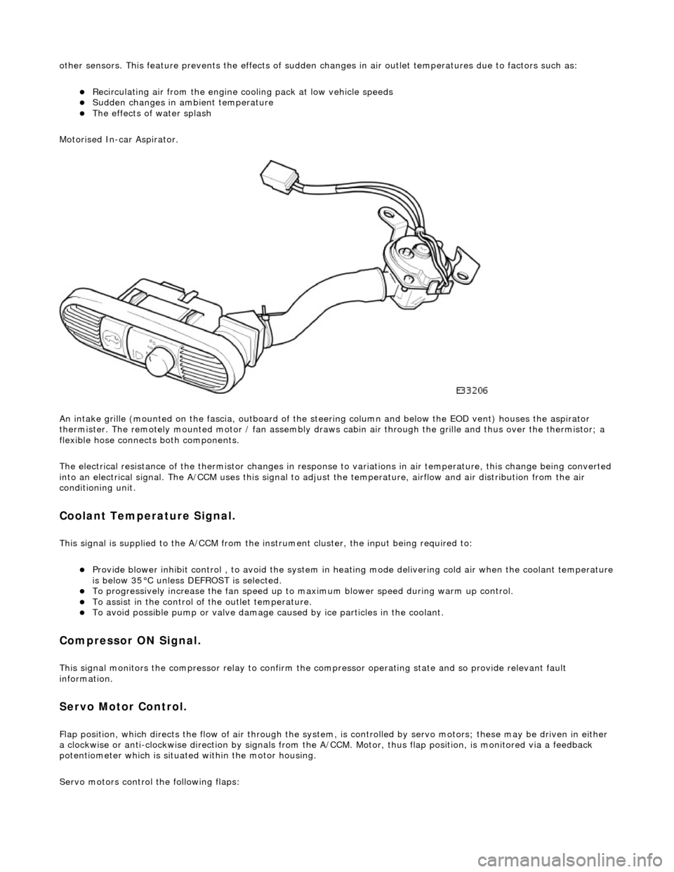
Motorised In-car Aspirator.
An intake grille (mounted on the fascia , outboard of the steering column and below the EOD vent) houses the aspirator
thermister. The remotely mounted motor / fan assembly draws ca bin air through the grille and thus over the thermistor; a
flexible hose connects both components.
The electrical resistance of the thermistor changes in response to variations in air temperatur e, this change being converted
into an electrical signal. The A/CCM uses this signal to adjust the temperature, airflow and air distribution from the air
conditioning unit.
Coolant Temperature Signal.
This signal is supplied to the A/CCM from the instrument cluster, the input being required to:
Provide blower inhibit control , to avoid the system in heat ing mode delivering cold air when the coolant temperature is below 35°C unless DEFROST is selected. To progressively increase the fan speed up to maximum blower speed during warm up control. To assist in the control of the outlet temperature. To avoid possible pump or valve damage ca used by ice particles in the coolant.
Compressor ON Signal.
This signal monitors the compressor relay to confirm the compressor operating state and so provide relevant fault
information.
Servo Motor Control.
Flap position, which directs the flow of air through the system, is controlled by servo motors; these may be driven in either
a clockwise or anti-clockwise direction by signals from the A/ CCM. Motor, thus flap position, is monitored via a feedback
potentiometer which is situated within the motor housing.
Servo motors control the following flaps:
Page 1833 of 2490

Control Components - Control Components
Diagnosis and Testing
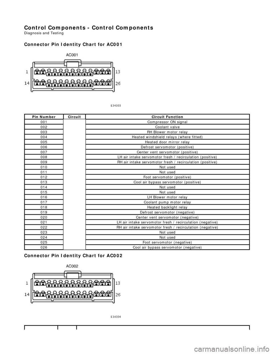
Connector Pin Identity Chart for AC001
Connector Pin Identity Chart for AC002
Pin NumberCircuitCircuit Function
001Compressor ON signal
002Coolant valve
003RH Blower motor relay
004Heated windshield relays (where fitted)
005Heated door mirror relay
006Defrost servomotor (positive)
007Center vent servomotor (positive)
008LH air intake servomotor fre sh / recirculation (positive)
009RH air intake servomotor fresh / recirculation (positive)
010Not used
011Not used
012Foot servomotor (positive)
013Cool air bypass servomotor (positive)
014Not used
015Not used
016LH Blower motor relay
017Coolant pump motor relay
018Heated backlight relay
019Defrost servomotor (negative)
020Center vent servomotor (negative)
021LH air intake servomotor fresh / recirculation (negative)
022RH air intake servomotor fresh / recirculation (negative)
023Not used
024Not used
025Foot servomotor (negative)
026Cool air bypass servomotor (negative)
Page 1835 of 2490

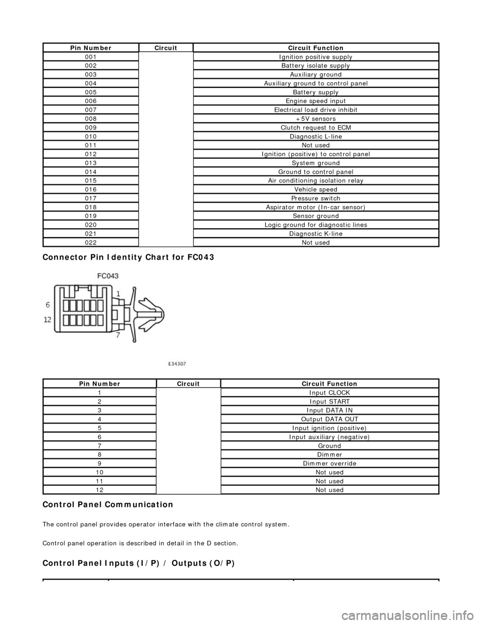
Connector Pin Identity Chart for FC043
Control Panel Communication
The control panel provides operator interface with the climate control system.
Control panel operation is described in detail in the D section.
Control Panel Inputs (I/P) / Outputs (O/P)
Pin NumberCircuitCircuit Function
001Ignition positive supply
002Battery isolate supply
003Auxiliary ground
004Auxiliary ground to control panel
005Battery supply
006Engine speed input
007Electrical load drive inhibit
008+5V sensors
009Clutch request to ECM
010Diagnostic L-line
011Not used
012Ignition (positive) to control panel
013System ground
014Ground to control panel
015Air conditioning isolation relay
016Vehicle speed
017Pressure switch
018Aspirator motor (In-car sensor)
019Sensor ground
020Logic ground for diagnostic lines
021Diagnostic K-line
022Not used
Pin NumberCircuitCircuit Function
1Input CLOCK
2Input START
3Input DATA IN
4Output DATA OUT
5Input ignition (positive)
6Input auxiliary (negative)
7Ground
8Dimmer
9Dimmer override
10Not used
11Not used
12Not used
Page 1859 of 2490
Horn - Horn
Description and Operation
The horns, located behind the radiator gril le, each side of the radiator, are controlled by the Body Processor Module (BPM),
as described below.
The switch, located on the steering wheel pad, is operated, it signals the BPM to sound the horn. The BPM responds by
providing an earth from the horn-output to the horn relay coil. The relay contacts are subsequently closed and the horns
sound.
The horn operating relay, R6 is located in the engine compartm ent fusebox at the left hand side of the engine compartment.
Page 1860 of 2490
Horn - Horn
Diagnosis and Testing
Tests Using the Portable Diagnostic Unit
Refer to PDU User Guide
The complexity of the electronics involved with the various Electronic Control Modules and the multiplexed communication
networks, preclude the use of workshop general electrical test equipment. Therefore, reference should be made to the PDU
User Guide for detailed instructions on test ing the horn circuit.
The PDU systematically tests an d analyses all functions of the horn, the horn relay, the bo dy processor module and the
operating switch.
Where a fault involving the horn, relay or switch is indicate d by the PDU, before replacing the component, some basic
diagnostic methods may be necessary to confirm that co nnections are good and that wiring is not damaged.
Page 1870 of 2490
Parking Aid - Parking Aid
Diagnosis and Testing
Inspection and Verification
1.1. Verify the customer concern.
2. 2. Visually inspect for obvious signs of mechanical or electrical damage.
Visual Inspection Chart
3. 3. If an obvious cause for an observed or reported concern is found, correct the cause (if possible) before proceeding to the next step
4. 4. If the cause is not visually evident, verify the sympto m and refer to the Jaguar approved diagnostic system.
Electrical
Fuse(s) Relay(s) Wiring Harness Electrical connector(s) Rear parking aid sensor(s) Rear parking aid speaker Reversing lamp switch Parking aid module
Page 1920 of 2490

Direction indicator and side marker lamps
Each front direction indicator and side marker lamp is retained in the bumper cover by a lug at one end and a spring clip at
the other end. The side marker lamps are not electrically connected for certain markets.
The side repeater lamps are secured by sp ring clips on the lower edge of the lamp unit. In certain markets Jaguar leaper
badges are substituted for side repeater lamps.
Fog lamps
The fog lamps are located in recesses in the front bump er and secured by three screws. The la mps which are not
interchangeable left to right, are accessed from the rear of the bumper.
Operation
All lamps are controlled by the BPM which provides an appropriate output in response to an input received when a selected
switch is operated.
All lamps receive an input direct from th e BPM with the exception of the main be am, dip beam and front fog lamps which
receive an input from the BPM vi a the respective relays and fuses; refer to section 418-01.
Fault analysis must be undertaken using the PDU. Refer to Diagnosis and Testing.
Consult the relevant Electrical Guid e for details of circuit operation.
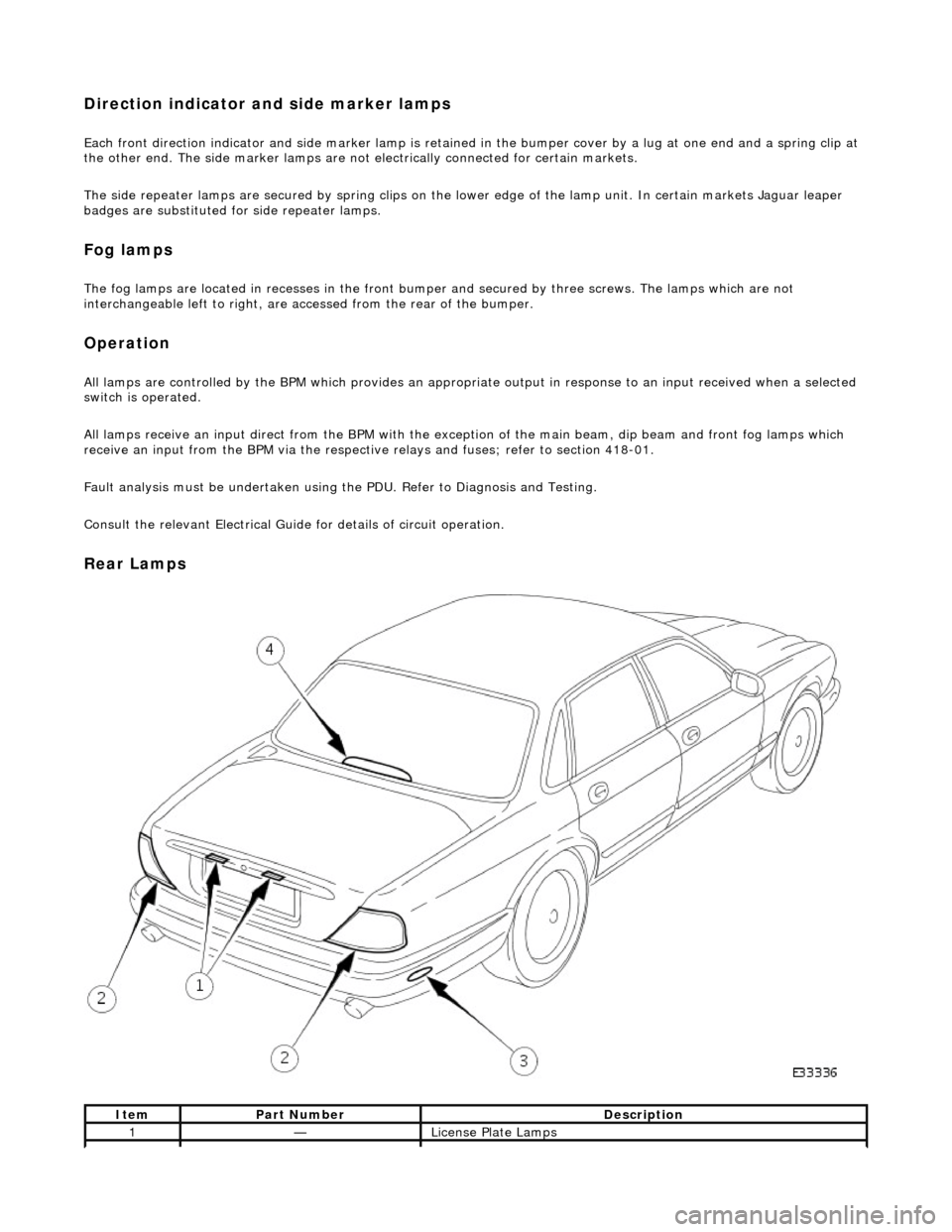
Rear Lamps
ItemPart NumberDescription
1—License Plate Lamps