Page 1227 of 2490

Di
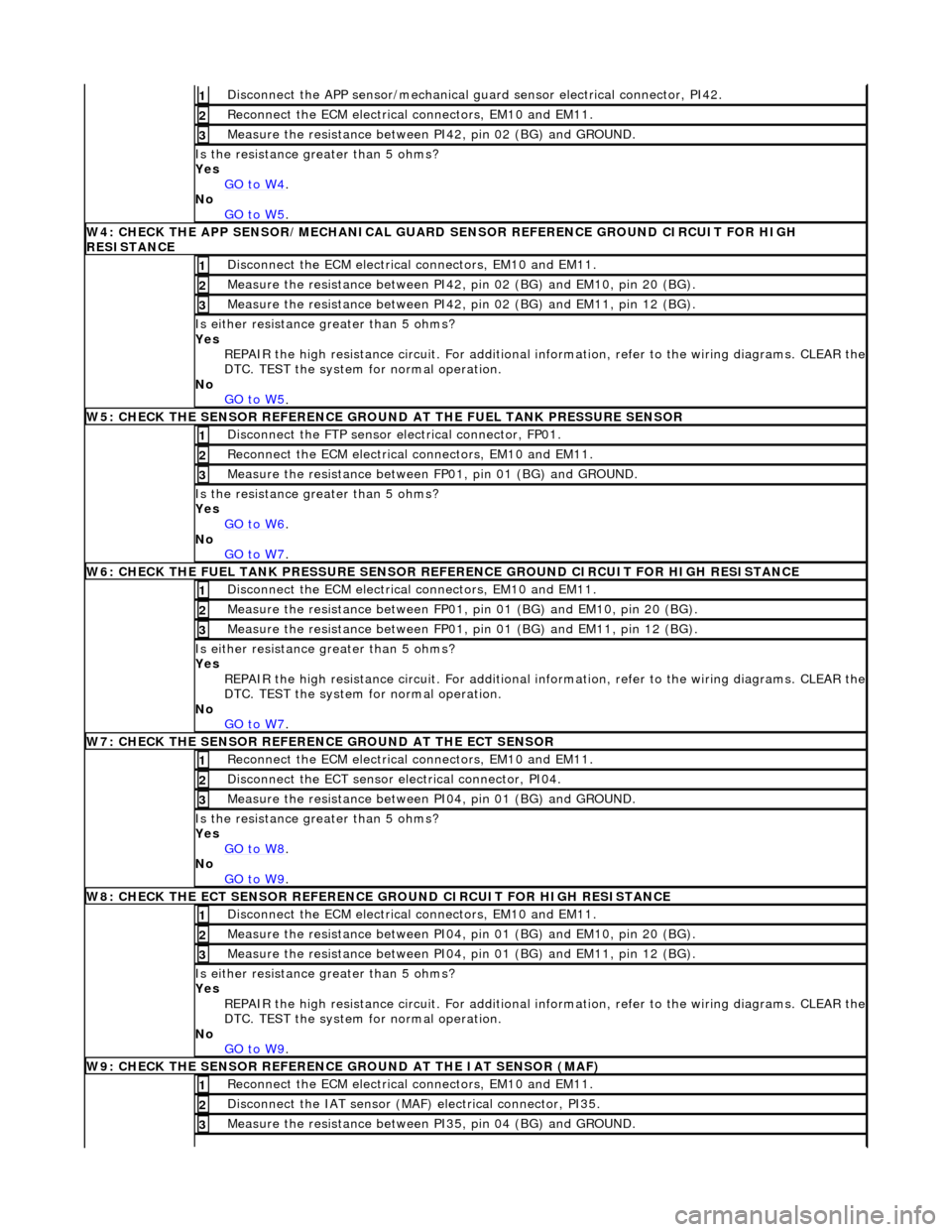
sconnect the APP sensor/mechanical guard sensor electrical connector, PI42.
1
Re
connect the ECM electrical connectors, EM10 and EM11.
2
Meas
ure the resistance between PI42, pin 02 (BG) and GROUND.
3
Is th
e resistance greater than 5 ohms?
Yes GO to W4
.
No
GO to W5
.
W4: CHECK THE APP
SENSOR/MECHANICAL GUARD SE
NSOR REFERENCE GROUND CIRCUIT FOR HIGH
RESISTANCE
D
isconnect the ECM electrical connectors, EM10 and EM11.
1
Meas
ure the resistance between PI42,
pin 02 (BG) and EM10, pin 20 (BG).
2
Meas
ure the resistance between PI42,
pin 02 (BG) and EM11, pin 12 (BG).
3
Is either resi
stance
greater than 5 ohms?
Yes REPAIR the high resistance circuit. For additional information, refer to the wiring diagrams. CLEAR the
DTC. TEST the system for normal operation.
No GO to W5
.
W5: CHECK THE SENSO
R REFERENCE GROUND AT THE FUEL TANK PRESSURE SENSOR
Di
sconnect the FTP sensor electrical connector, FP01.
1
Re
connect the ECM electrical connectors, EM10 and EM11.
2
Meas
ure the resistance between
FP01, pin 01 (BG) and GROUND.
3
Is th
e resistance greater than 5 ohms?
Yes GO to W6
.
No
GO to W7
.
W6: CHECK THE FUEL
TANK PRESSURE SENSOR RE
FERENCE GROUND CIRCUIT FOR HIGH RESISTANCE
D
isconnect the ECM electrical connectors, EM10 and EM11.
1
Meas
ure the resistance between FP01,
pin 01 (BG) and EM10, pin 20 (BG).
2
Meas
ure the resistance between FP01,
pin 01 (BG) and EM11, pin 12 (BG).
3
Is either resi
stance
greater than 5 ohms?
Yes REPAIR the high resistance circuit. For additional information, refer to the wiring diagrams. CLEAR the
DTC. TEST the system for normal operation.
No GO to W7
.
W7: CHECK THE SENSO
R REFERENCE GROUND AT THE ECT SENSOR
Re
connect the ECM electrical connectors, EM10 and EM11.
1
D
isconnect the ECT sensor electrical connector, PI04.
2
Meas
ure the resistance between PI04, pin 01 (BG) and GROUND.
3
Is th
e resistance greater than 5 ohms?
Yes GO to W8
.
No
GO to W9
.
W8: CHECK THE ECT SEN
SOR REFERENCE
GROUND CIRCUIT FOR HIGH RESISTANCE
D
isconnect the ECM electrical connectors, EM10 and EM11.
1
Meas
ure the resistance between PI04,
pin 01 (BG) and EM10, pin 20 (BG).
2
Meas
ure the resistance between PI04,
pin 01 (BG) and EM11, pin 12 (BG).
3
Is either resi
stance
greater than 5 ohms?
Yes REPAIR the high resistance circuit. For additional information, refer to the wiring diagrams. CLEAR the
DTC. TEST the system for normal operation.
No GO to W9
.
W9: CHECK THE SENSO
R REFERENCE GR
OUND AT THE IAT SENSOR (MAF)
Re
connect the ECM electrical connectors, EM10 and EM11.
1
Di
sconnect the IAT sensor (MAF) electrical connector, PI35.
2
Meas
ure the resistance between PI35, pin 04 (BG) and GROUND.
3
Page 1233 of 2490
E
lectronic Engine Controls - Ca
mshaft Position (CMP) Sensor
Re
moval and Installation
Remov
al
1.
Disc
onnect battery ground cable (IMPORTANT, see SRO
86.15.19 for further information).
2. Remove engine covers ; refer to 12.30.06.
3. WARNING: BEFORE PROCEEDING, IT IS ESSENTIAL THAT
THE WARNING NOTES GIVEN IN SECTION 100-00 (UNDER THE
HEADING 'SAFETY PRECAUTIONS') ARE READ AND
UNDERSTOOD.
De-pressurize fuel system; refer to 19.50.02.
4. R
emove coolant expansion tank fixings and reposition tank for
access.
5. R
emove bolts securing fuel fe
ed pipe to inlet manifold.
6. Di
sconnect fuel feed pipe from inlet manifold and pull pipe
assembly clear.
Di
scard O-ring.
Inst
all suitable blanking plugs.
7. Disconnect CMP sensor connector.
De
press tang on connector to release, tools are not
necessary.
Page 1235 of 2490
3. Conne
ct CMP sensor connector.
4. Connect
fuel feed pipe to inlet manifold.
R
emove blanking plugs.
Install and lubricate new O-r
ing.
5. Install
bolts securing fuel feed
pipe to the inlet manifold.
6. Install coolant expansion tank.
Page 1242 of 2490

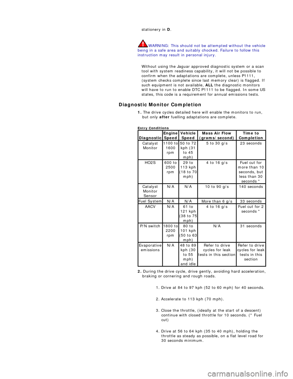
Diagnostic Monitor Comp
letion
stat
ionery in
D.
WARNING: This should not be attempted without the vehicle
being in a safe area and suitably chocked. Failure to follow this
instruction may result in personal injury.
Without using the Jaguar approved diagnostic system or a scan
tool with system readiness capability, it will not be possible to
confirm when the adaptations are complete, unless P1111,
(system checks complete since last memory clear) is flagged. If
such equipment is not available, ALL the diagnostic monitors
will have to run to enable DTC P1111 to be flagged. In some US
states, this code is a requirem ent for annual emissions tests.
1. The dri v
e cycles detailed here w
ill enable the monitors to run,
but only after fuelling adaptations are complete.
Entry C
onditions
Di
agno
stic
Engine
S p
eed
Ve
h
icle
Speed
Mass Air Flow
(gra ms/sec
ond)
Ti
m
e to
Completion
Catalyst Monitor1 100
to
1600 rpm
50 to
72
kph (31 to 45
mph)
5 to
30 g/s
23
se
conds
HO2S6
00 t
o
2500 rpm
29 to
113 kph
(18 to 70
mph)
4 to
16 g/s
F
u
el cut for
more than 10 seconds, but less than 30 seconds *
Catalyst Monitor SensorN/ AN/A10
to 90 g/s
14
0
seconds
F
u
el System
N/
AN/AMore than 6 g/s33 se
conds
AACVN/
A61 to
121 kph
(38 to 75
mph)
4 to
16 g/s
F
u
el cut for 2
seconds *
P /
N switch
1
800
to
2200 rpm
80 to
101 kph
(50 to 63
mph)
N/ A31 se
conds
Evaporative
em is
sions
N/
A48 to
89
kph (30 to 55
mph)
and idle
R e
fer to drive
cycles for leak
tests in this section
Re
fer to drive
cycles for leak
tests in this section
2. During the drive cycle, drive gent ly, avoiding hard acceleration,
braking or cornering and rough roads.
1. Drive at 84 to 97 kph (52 to 60 mph) for 40 seconds.
2. Accelerate to 113 kph (70 mph).
3. Close the throttle, (ideally at the start of a descent)
continue with closed throttle for 10 seconds. (* Fuel
cut)
4. Drive at 56 to 64 kph (35 to 40 mph), holding the throttle as steady as possib le, on a flat level road for
30 seconds minimum.
Page 1525 of 2490
The left-hand and right-hand do wnpipe assemblies feature:
Catalytic converter with palladium / rhodium coated elem ents. The elements are uncoated for markets with only
leaded fuel.
Retained to the exhaust manifold flange by four thread ed studs. Joint-to-joint sealing is with a gasket. Engine-mounted bracket providing downpipe mounting by two nuts to the torque converter housing and two bolts to
the downpipe.
Front Muffler Assembly
ItemPart NumberDescription
1—Downpipe catalytic converter
2—Upstream heated oxygen sensor
3—Downstream oxygen sensor (North American markets only)
4—Engine mounting bracket (LHS and RHS)
Page 1530 of 2490
The upstream heated oxygen sensor is located at the catalytic converter inlet and detects the concentration of oxygen in the
raw exhaust gases; an internal heater reduces the warm up time of the sensor output.
An oxygen sensor (without heater) is located at the converter outlet.
The ECM receives input signals from the se nsors and varies the fuel injector duration (mixture) to provide optimum gas
emissions.
Circuit Diagram, O2 Sensors / ECM
Page 1692 of 2490

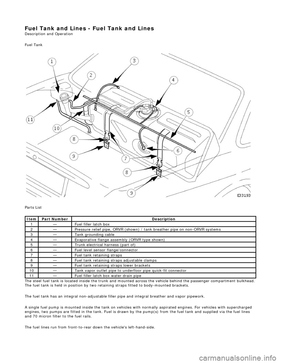
Fuel Tank and Lines - Fuel Tank and Li
nes
Description an
d Operation
Fuel Tank
Parts List
The steel fuel tank is located inside the trunk and mounted across the vehicle behind the passenger compartment bulkhead.
The fuel tank is held in posi tion by two retaining straps fi tted to body-mounted brackets.
The fuel tank has an integral non-adjustable fill er pipe and integral breather and vapor pipework.
A single fuel pump is mounted inside the tank on vehicles with normally aspirated engines. For vehicles with supercharged
engines, two pumps are fitted in the tank. Fuel is drawn by the pump(s) from the fuel tank and supplied via the fuel lines
and 70 micron filter to the fuel rails.
The fuel lines run from front-to-rear down the vehicle's left-hand-side.
Ite
m
Part
Number
Descr
iption
1—Fu
el filler latch box
2—Pressure reli
ef pipe, ORVR
(shown) / tank breather pipe on non-ORVR systems
3—Tank grounding
cable
4—Evaporative flan
ge assembly
(ORVR type shown)
5—Trunk elec
trical harne
ss (part of)
6—Fue
l
level sensor
flange/connector
7—Fu
el tank retaining straps
8—F
u
el tank retaining stra
ps adjustable clamps
9—Fu
el tank retaining straps lower brackets
10—Tank vapor outlet pipe to un
derflo
or pipe quick-fit connector
11—F
u
el filler latch bo
x water drain pipe
Page 1693 of 2490

Filler Cap and P
ipe
The fuel
filler cap with bayonet-type fixi
ng is located beneath a remote-release sp ring-latched lid on the rear saddle panel
on the left-hand-side of the vehicle.
Fuel Pum
p
The fu
el pump(s) is energized by an ECM co
ntrolled relay. Fuel is drawn by this pu mp and supplied to the fuel injectors via
the fuel line, filter and fuel rails.
Servicing of the fuel pump re quires fuel tank removal.
Ev
aporative Loss Flange Assembly
The evaporative-loss flan
ge asse
mbly is mounted centrally on top of the tank. The flange assembly consists of a removeable
steel cap which mounts the evaporative emissions system vapor outlet valves and, if applicable, a pressure sensor. The
external electrical supply to th e fuel pump(s) is also made via a connector on the flange.
The flange assembly is fixed to the tank by a locking ring which is turned usin g special tool JD-174. A seal is fitted between
the flange assembly and the tank. Three di fferent flange assemblies are applicable according to the evaporative emission
system fitted to the vehicle. The fl ange size and fixing are identical fo r the three systems, as described.
Removal of the evaporative flange assembly is necessary to gain access to th e fuel pump(s) and other internal components.
To remove the evaporative fl ange assembly the fuel tank must first be removed.
The evaporative flange variant assemblies are described, together with service information, in Section 303-13.
Fuel R
eturn
Excess fuel
is directed back to
the fuel tank via a return line.
Fuel Pum
p Relay
The
fuel pump relay,
under control of the ECM, switches power to the fuel pump motor.
I
nertia Fuel Shutoff (IFS) Switch
The IF
S switch is located in the right-hand
side footwell behind the footboard carpet . When activated the switch isolates the
ignition system and fuel pump, releases any locked doors and disables unnecessary electrical systems. The system can be
reset by pressing down the flexible cover on the top of the switch.
• NOTE: The doors will not unlock if the IFS switch is tripped when the ignition switch is in position '0'.