1998 JAGUAR X308 fuel sensor
[x] Cancel search: fuel sensorPage 1156 of 2490
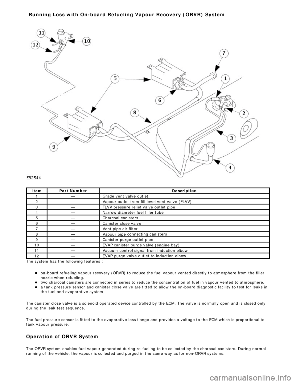
The system has the
following features :
o
n
-board refueling vapour recovery (ORVR) to reduce the fu
el vapour vented directly to atmosphere from the filler
nozzle when refueling.
two ch arcoal
canisters are connected in series to reduce th
e concentration of fuel in vapour vented to atmosphere.
a t
ank pressure sensor and canister close
valve are fitted to allow the on-board di agnostic facility to test for leaks in
the fuel and evaporative system.
The canister close valve is a solenoid operated device controlled by the ECM. The valve is normally open and is closed only
during the leak test sequence.
The fuel pressure sensor is fitted to th e evaporative loss flange and provides a volt age to the ECM which is proportional to
tank vapour pressure.
Op era
tion of ORVR System
The ORVR system enabl
e
s fuel vapour generated during re-fueling to be collected by
the charcoal canisters. During normal
running of the vehicle, the vapour is collected and purged in the same way as for non-ORVR systems.
Ite
m
Par
t
Number
De
scr
iption
1—Grade vent
valve outl
et
2—Vapour outl
et from fil
l level vent valve (FLVV)
3—F
L
VV pressure relief valve outlet pipe
4—N
a
rrow diameter fuel filler tube
5—Charcoal can
i
sters
6—Cani
st
er close valve
7—Vent pi
pe ai
r filter
8—Vapour pipe
conn
ecting canisters
9—Canister purge ou
tlet pipe
10—EVAP canister purge v a
lve (engine bay)
11—Vacuu
m
control signal from induction elbow
12—EVAP pu
rge valve outlet to induction elbow
Running Loss with On-board R
efuelin
g Vapour Recovery (ORVR) System
Page 1158 of 2490
The fuel fil
ler cap is the same as
that used on non-ORVR systems.
The check valve assembly is a push fit into the end of the fuel filler tube and is accessible with the evaporative flange
removed. The valve has a light spring load ing and opens under the inflow of fuel.
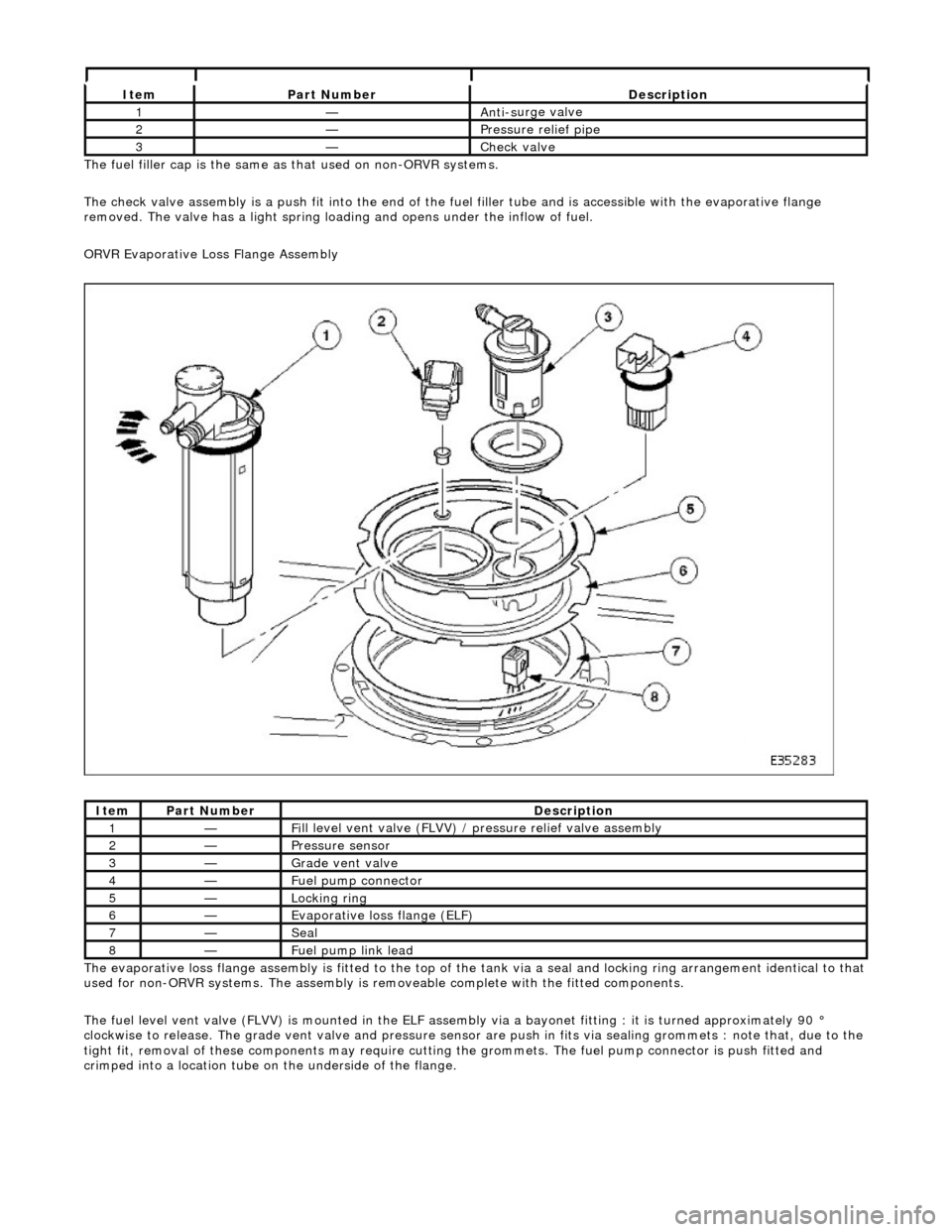
ORVR Evaporative Loss Flange Assembly
The evaporative loss flange assembly is fitted to the top of the tank via a seal and locking ring arrangement identical to that
used for non-ORVR systems. The assembly is re moveable complete with the fitted components.
The fuel level vent valve (FLVV) is mounted in the ELF assembly via a bayonet fitting : it is turned approximately 90 °
clockwise to release. The grade vent valve and pressure sensor are push in fits via sealing gromme ts : note that, due to the
tight fit, removal of these components may require cutting the grommets. The fuel pump connector is push fitted and
crimped into a location tube on the underside of the flange.
It e
m
Par
t
Number
De
scr
iption
1—An
ti-s
urge valve
2—Pressure rel
i
ef pipe
3—Check v
a
lve
It
e
m
Par
t
Number
De
scr
iption
1—Fi
ll
level vent valve (FLVV) /
pressure relief valve assembly
2—Pres
sure
sensor
3—Grade vent
valve
4—Fue
l
pump connector
5—Lockin
g rin
g
6—Evaporative loss flange (ELF)
7—Seal
8—F
u
el pump link lead
Page 1162 of 2490
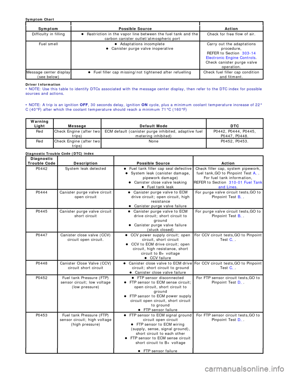
Driver Info
rmation
•
NOTE: Use this table to identify DTCs associated with the me
ssage center display, then refer to the DTC index for possible
sources and actions.
• NOTE: A trip is an ignition OFF, 30 seconds delay, ignition ON cycle, plus a minimum coolant temperature increase of 22°
C (40°F) after which the coolant temperat ure should reach a minimum 71°C (160°F)
Diagnostic Trouble C
ode (DTC) index
Sy
m
ptom
Possib
l
e Source
Acti
o
n
D
i
fficulty in filling
R
e
striction in the vapor line between the fuel tank and the
carbon canister outlet/atmospheric port
Check f or free f
low of air.
F
u
el smell
Adaptat
i
ons incomplete
Cani
st
er purge valve inoperative
Carry
o
ut the adaptations
procedure,
REFER to Section 303
-14 Ele c
tronic Engine Controls
.
Chec k cani
ster purge valve
operation.
M e
ssage center display
(see below)
Fue l
filler cap missing/not
tightened after refuelling
Check fu
el filler cap condition
and fitment.
Warning Li
ght
Mess
age Defaul
t Mode
DT
C
RedCheck Engine (after two
trip
s)
ECM de
fa
ult (canister purge inhibited, adaptive fuel
metering inhibited)
P0442,
P0444, P0445,
P0447, P0448.
Re dCheck Engine (after two
trip
s)
No
neP04 52,
P0453.
Di
agno
stic
Trouble Code
De scr
iption
Possib
l
e Source
Acti
o
n
P0442Sy
st
em leak detected
F
u
el tank filler cap seal defective
Sy
ste
m leak (c
anister damage,
pipework damage)
Cani st
er close valve leaking
F
u
el tank leak
Chec
k fi
ller cap,
system pipework,
fuel tank,GO to Pinpoint Test A.
.
F o
r fuel tank information,
REFER to Section 310
-01 Fu
el Tank
and Lines.
P0444Canist
er purge valve circuit
open circuit
Cani st
er purge valve to ECM
drive circuit; open circuit, high
resistance
Cani st
er purge valve failure
F
or purge
valve circuit tests,GO to
Pinpoint Test B.
.
P0445Canist
er purge valve circuit
short circuit
Cani st
er purge valve to ECM
drive circuit; short circuit to ground
Canist
er purge valve failure
(stuck closed)
F or purge
valve circuit tests,GO to
Pinpoint Test B.
.
P0447Canist
er close valve (CCV)
circuit open circuit.
CCV power su pply ci
rcuit; open
circuit, short circuit
CCV to ECM drive circuit;
open
circuit, high resistance, short circuit to B+ voltage
CCV failure
Fo
r CCV circuit tests,GO to Pinpoint
Test C.
.
P0448Canist
er Close Valve (CCV)
circuit short circuit
Cani st
er close valve to ECM drive
circuit; short circuit to ground
Cani st
er close valve failure
F
o
r CCV circuit tests,GO to Pinpoint
Test C.
.
P0452 Fu
el tank Pressure (FTP)
sensor circuit; low voltage (low pressure)
FTP sen
sor disconnected
FTP sen
sor to ECM sense circuit;
open circuit, short circuit to ground
FTP sens
or to ECM power supply
circuit open circuit, short circuit to ground
FT
P sensor failure
For FT
P se
nsor circuit tests,GO to
Pinpoint Test D.
.
P0453Fu
el tank Pressure (FTP)
sensor circuit; high voltage
(high pressure)
FTP sen
sor to ECM signal ground
circuit open circuit
F T
P sensor to ECM wiring
(supply, sense, signal ground),
short circuit to each other
FTP sen
sor to ECM sense circuit
short circuit to B+ voltage
For FT P se
nsor circuit tests,GO to
Pinpoint Test D.
.
FT
P sensor failure
Sym
ptom Chart
Page 1164 of 2490
"d
iagnostic drive cycles" above.
No GO to B2
.
B2: CHECK THE PURGE VALVE DR
IV
E CIRCUIT FOR SHORT TO GROUND
Re
connect the battery negative terminal.
1
Meas
ure t
he resistance between EM39, pin 02 (PN for vehicles with AJ26
engine, UY for vehicles with
AJ27 engine), and GROUND.
2
Is t
he resistance less than 10,000 ohms?
Yes REPAIR the short circuit. For addi tional information, refer to the wiring diagrams. CLEAR the DTC.
Carry out a full Evaporative system monitor drive cycle.
No INSTALL a new purge valve,
REFER to Evaporative Emission Canister Purge Valve
- in thi
s section.
CLEAR the DTC. Carry out a full Evaporative system monitor drive cycle. Recheck DTCs. For additional
information, see "diagnostic drive cycles" above. If the DTC is repeated, contact dealer technical
support for advice on possible ECM failure.
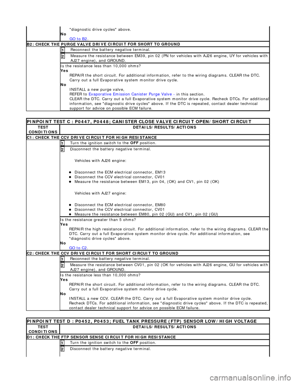
PI
NPOINT TEST C : P0447, P0448; CANISTER CLOSE VALVE CIRCUIT OPEN/SHORT CIRCUIT
TE
S
T
CONDITIONS
D E
TAILS/RESULTS/ACTIONS
C1
: CH
ECK THE CCV DRIVE CIRCUIT FOR HIGH RESISTANCE
Turn the ignition swi
t
ch to the
OFF position.
1
Disc
onnect the battery negative terminal.
Vehicles with AJ26 engine:
Disc onne
ct the ECM electrical connector, EM13
Di
sc
onnect the CCV electrical connector, CV01
Meas
ure t
he resistance between EM13, pi
n 04, (OK) and CV1, pin 02 (OK)
Vehicles with AJ27 engine:
Disc onne
ct the ECM electrical connector, EM80
Di
sc
onnect the CCV electrical connector, CV01
Meas
ure t
he resistance between EM80,
pin 02 (GU) and CV1, pin 02 (GU)
2
Is the res
istance greater than 5 ohms?
Yes REPAIR the high resistance circuit. For additional information, refer to the wiring diagrams. CLEAR the
DTC. Carry out a full Evaporative system monitor drive cycle. For additional information, see
"diagnostic drive cycles" above.
No GO to C2
.
C2: CH
ECK THE CCV DRIVE CIRCUI
T FOR SHORT CIRCUIT TO GROUND
Re
connect the battery negative terminal.
1
Meas
ure t
he resistance between CV01,
pin 02 (OK for vehicles with AJ26 engine, GU for vehicles with
AJ27 engine), and GROUND.
2
Is t
he resistance less than 10,000 ohms?
Yes REPAIR the short circuit. For addi tional information, refer to the wiring diagrams. CLEAR the DTC.
Carry out a full Evaporative system monitor drive cycle.
No INSTALL a new CCV. CLEAR the DTC. Carry out a fu ll Evaporative system monitor drive cycle.
Recheck DTCs. For additional inform ation, see "diagnostic drive cycles" above. If the DTC is repeated,
contact dealer technical support for advice on possible ECM failure.
P INPOINT TES
T D : P0452, P0453; FUEL TANK
PRESSURE (FTP) SENSOR LOW/HIGH VOLTAGE
TES
T
CONDITIONS
DE
TAILS/RESULTS/ACTIONS
D
1:
CHECK THE FTP SENSOR SENSE CIRCUIT FOR HIGH RESISTANCE
Turn the ignition swi
t
ch to the OFF
position.
1
Disc
onnect the battery negative terminal.
2
Page 1171 of 2490
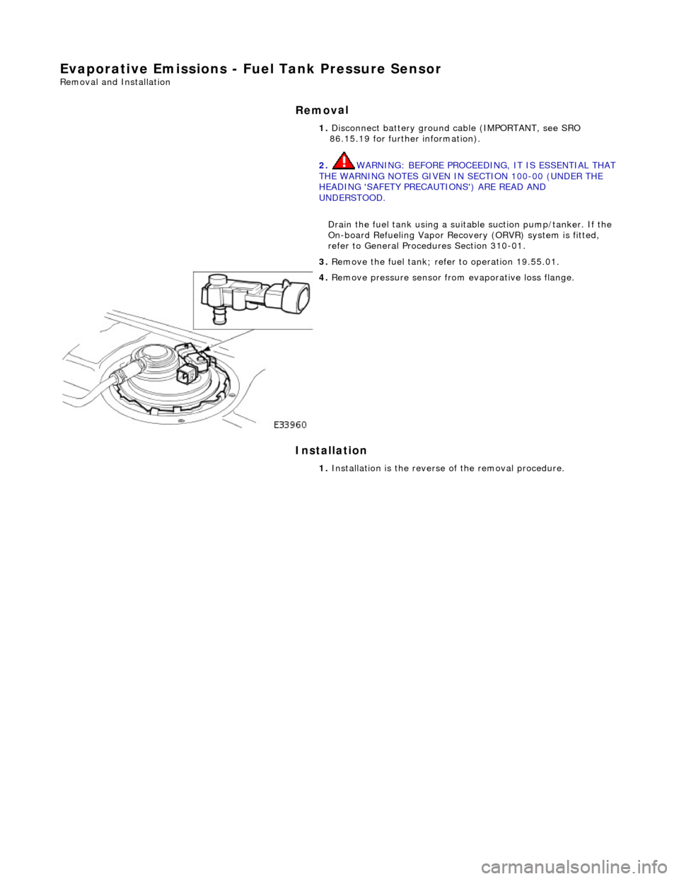
E
vaporative Emissions - Fuel
Tank Pressure Sensor
Re
moval and Installation
Remov
al
Installation
1.
Disc
onnect battery ground cable (IMPORTANT, see SRO
86.15.19 for further information).
2. WARNING: BEFORE PROCEEDING, IT IS ESSENTIAL THAT
THE WARNING NOTES GIVEN IN SECTION 100-00 (UNDER THE
HEADING 'SAFETY PRECAUTIONS') ARE READ AND
UNDERSTOOD.
Drain the fuel tank using a suitab le suction pump/tanker. If the
On-board Refueling Vapor Recove ry (ORVR) system is fitted,
refer to General Procedures Section 310-01.
3. R
emove the fuel tank; refe
r to operation 19.55.01.
4. R
emove pressure sensor fro
m evaporative loss flange.
1. Installation is th e reverse of the re moval procedure.
Page 1177 of 2490
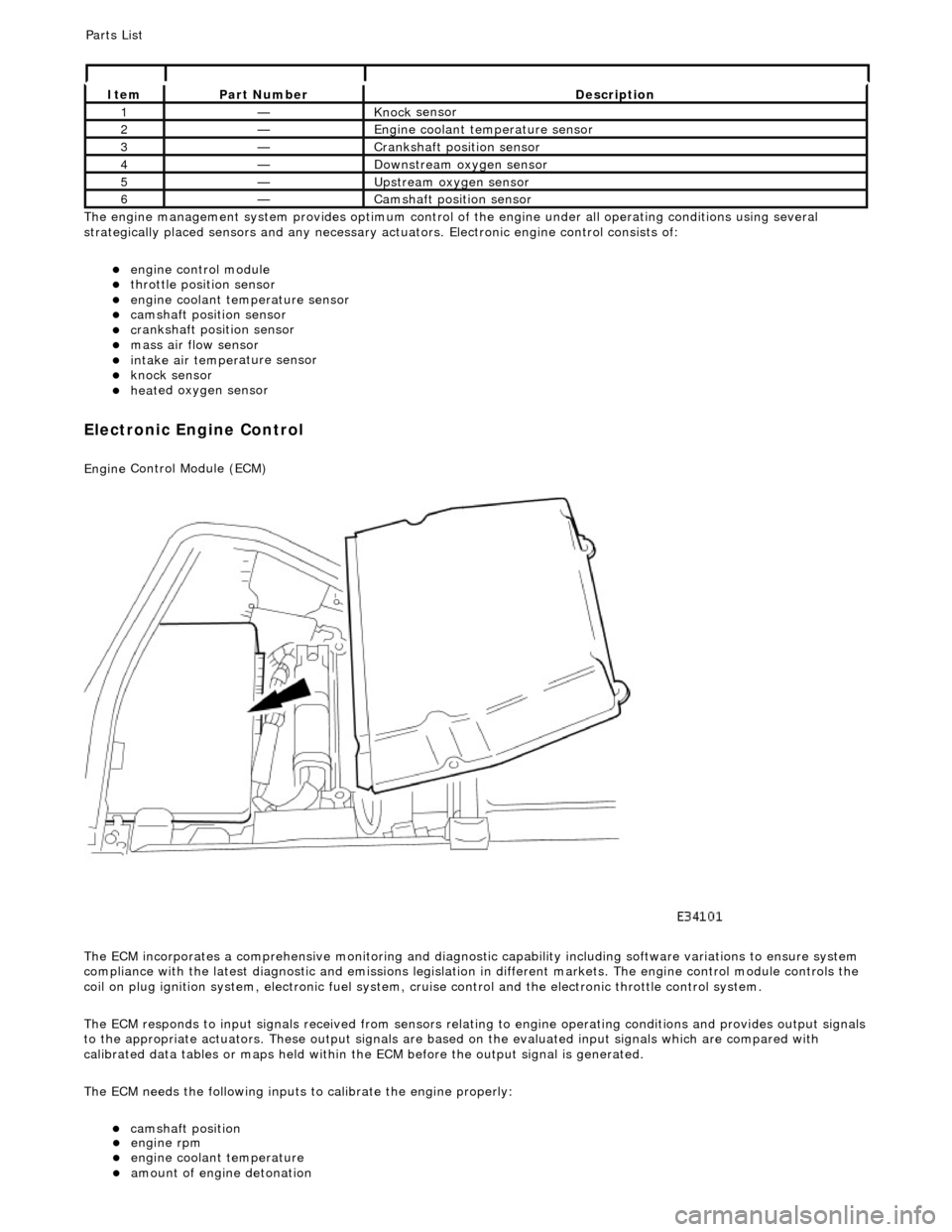
Th
e engine management system provides optimum control of
the engine under all operating conditions using several
strategically placed sensors and any necessary actuators. Electronic engine control consists of:
engine
control module
throttle posi
tion sensor
engi
ne coolant temperature sensor
cam
shaft position sensor
c
rankshaft position sensor
mass air
flow sensor
intake air temper
ature sensor
kn
ock sensor
heat
ed oxygen sensor
Electronic Engine Control
Engine
Control Module (ECM)
The ECM incorporates a comprehensive monitoring and diagnostic capability including software variations to ensure system
compliance with the latest diagnostic and emissions legislation in different markets. The engine control module controls the
coil on plug ignition system, electronic fuel system, cr uise control and the electronic throttle control system.
The ECM responds to input signals received from sensors relating to engine operatin g conditions and provides output signals
to the appropriate actuators. These outp ut signals are based on the evaluated input signals which are compared with
calibrated data tables or maps held within th e ECM before the output signal is generated.
The ECM needs the following inputs to calibrate the engine properly:
cam
shaft position
It
em
Par
t Number
De
scription
1—Knock
sensor
2—Engine
coolant temperature sensor
3—Cranksh
aft position sensor
4—D
ownstream oxygen sensor
5—Upstream oxygen sensor
6—Camshaft position
sensor
P
arts List
engi
ne rpm
engi
ne coolant temperature
amount
of engine detonation
Page 1178 of 2490
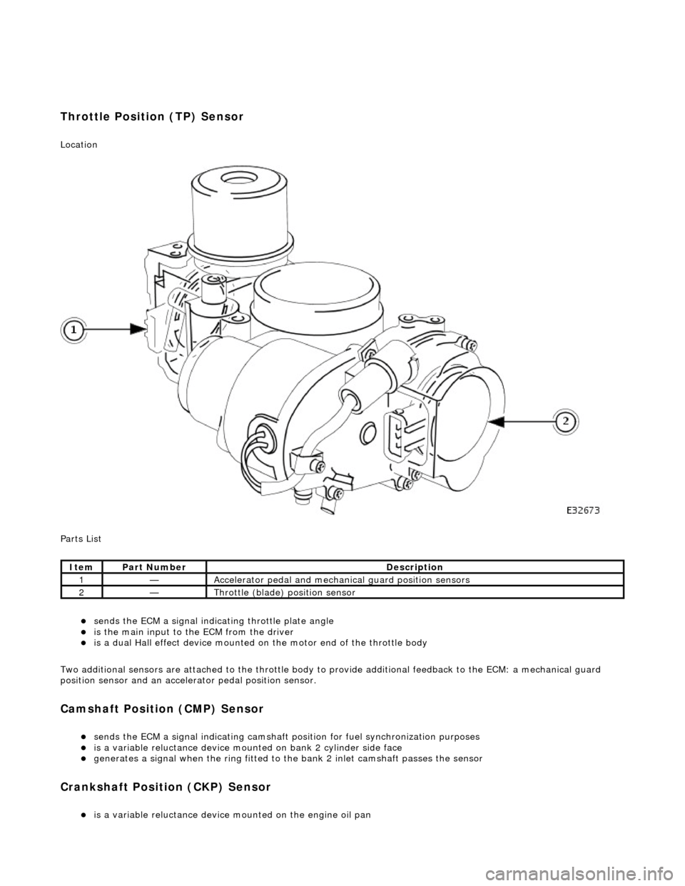
Throttle Position (TP) Sensor
Location
P
arts List
sen
d
s the ECM a signal indica
ting throttle plate angle
is
the main input to the ECM from the driver
i
s
a dual Hall effect devi
ce mounted on the motor en d of the throttle body
Two additional sensors are attached to the throttle body to provide additional feedback to the ECM: a mechanical guard
position sensor and an accelerator pedal position sensor.
Cam s
haft Position (CMP) Sensor
sen
d
s the ECM a signal indicating camshaft po
sition for fuel synchronization purposes
is
a variable reluctance device mounted on bank 2 cylinder side face
generates a signal when the ri
ng
fitted to the bank 2 inlet
camshaft passes the sensor
Cranksha
ft Position (CKP) Sensor
i
s
a variable reluctance device
mounted on the engine oil pan
Ite
m
Par
t
Number
De
scr
iption
1—Acce
le
rator pedal and mechanic
al guard position sensors
2—Throttle
(blade)
position sensor
Page 1179 of 2490
generates a signal when th
e dr
ive plate passes the sensor
sen
ds the ECM signals indicating crankshaft position and engine speed
is e
ssential for calculating spark timing
En
gine Coolant Temperature (ECT) Sensor
sen
ds the ECM a signal indicating the temperature of the engine coolant
is a t
emperature dependent resistor with a negative temperature coefficient (resistance changes inversely with
respect to temperature) and is constantly monitored by the ECM
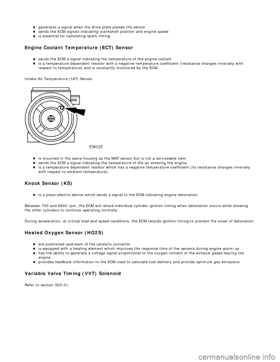
Intake Air Temperature (IAT) Sensor
is m
ounted in the same housing as the MA
F sensor but is not a serviceable item
sen
ds the ECM a signal indicating the temperature of the air entering the engine
is a t
emperature dependent resistor which has a negative
temperature coefficient (its resistance changes inversely
with respect to ambient temperature).
Knock S
ensor (KS)
is a pi
ezo-electric device which sends a signal
to the ECM indicating engine detonation
Between 700 and 6800 rpm, the ECM will retard individual cylinder ignition timing when detonation occurs while allowing
the other cylinders to continue operating normally.
During acceleration, at critical load and speed conditions, the ECM retards ignition timing to prevent the onset of detonation.
H
eated Oxygen Sensor (HO2S)
are
positioned upstream of the catalytic convertor
is equipped with
a heating element wh
ich improves the response time of the sensors during engine warm-up
h
as the ability to generate a voltage signal proportional to the oxygen content of the exhaust gases leaving the
engine
pr
ovides feedback information to the ECM used to calc
ulate fuel delivery and provide optimum gas emissions
Variable V
alve Timing (VVT) Solenoid
R
efer to section 303-01.