Page 1232 of 2490

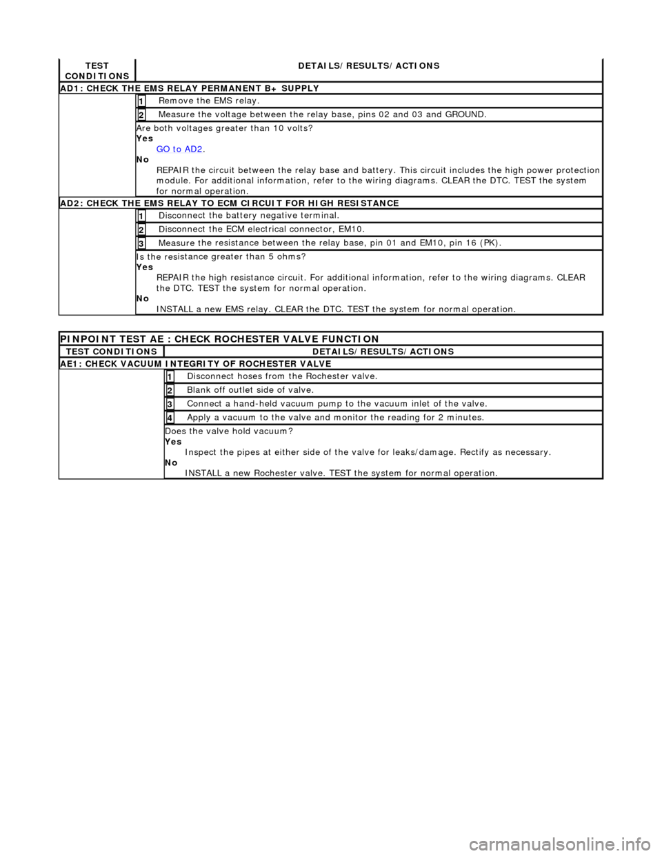
TES
T
CONDITIONS
D E
TAILS/RESULTS/ACTIONS
AD1
:
CHECK THE EMS RELAY PERMANENT B+ SUPPLY
R
e
move the EMS relay.
1
Meas
ure t
he voltage between the rela
y base, pins 02 and 03 and GROUND.
2
Are both vol
tages greater than 10 volts?
Yes GO to AD2
.
No
R
EPAIR the circuit between the rela
y base and battery. This circuit includes the high power protection
module. For additional information, refer to the wiring diagrams. CLEAR the DTC. TEST the system
for normal operation.
AD2 :
CHECK THE EMS RELAY TO ECM CIRCUIT FOR HIGH RESISTANCE
Di
sc
onnect the battery negative terminal.
1
D
i
sconnect the ECM electrical connector, EM10.
2
Meas
ure t
he resistance between the rela
y base, pin 01 and EM10, pin 16 (PK).
3
Is the res
istance greater than 5 ohms?
Yes REPAIR the high resistance circui t. For additional information, refer to the wiring diagrams. CLEAR
the DTC. TEST the system for normal operation.
No INSTALL a new EMS relay. CLEAR the DTC. TEST the system for normal operation.
PINPOINT TEST AE : CHECK
ROCHESTER VALVE FUNCTION
T
E
ST CONDITIONS
D
E
TAILS/RESULTS/ACTIONS
AE1: CHEC
K VAC
UUM INTEGRITY OF ROCHESTER VALVE
Di
sc
onnect hoses from the Rochester valve.
1
Bl
a
nk off outlet side of valve.
2
Con
n
ect a hand-held vacuum pump to the vacuum inlet of the valve.
3
Appl
y a vacuum t
o the valve and mo
nitor the reading for 2 minutes.
4
Do
es the valve hold vacuum?
Yes Inspect the pipes at either side of the valve for leaks/damage. Rectify as necessary.
No INSTALL a new Rochester valve. TEST the system for normal operation.
Page 1395 of 2490
and/or increased performance as appropriate.
Serial Communications Interfaces
Controller Area Network (CAN)
The TCM is an integral part of the CAN system which facilita tes the interchange of real-time data between control modules
and sensors; refer to 303-14 fo r a full description of CAN.
Transmission Pressure Regulators and Shift Solenoids Circuit Diagram
ItemPart NumberDescription
1—Transmission oil temperature sensor
2—Switch
3—Shift solenoid 1 <-> 2, 4 <-> 5
4—Shift solenoid 2 <-> 3
Page 1396 of 2490
Speed Sensor / TCM Circuit Diagram
Connector Pins Identification
Connector Pin Identity Chart for EM061
5—Shift solenoid 3 <-> 4
6—TCC pressure regulator
7—Modulation pressure regulator
8—Shift pressure regulator
9—Engine compartment fuse box
10—Transmission control module
11—Transmission
ItemPart NumberDescription
1—n2 speed sensor
2—n3 speed sensor
3—Engine compartment fuse box
4—Transmission control module
5—Transmission
Page 1468 of 2490
Operation
• NOTE: The rotary position switch is NOT adjustable.
The position of the gear selector lever is detected by the range sensor; a system which consists of two sensors (switch
systems). 1. 1. The rotary position switch, which is located on the RH side of the transmission case and is coaxial with the
selector shaft.
2. 2. The D to 4 (micro) switch, which is mounted in the 'J gate' assembly.
When the selector is moved across the ga te to engage 4, or back from that side towards D the selector cable does not
move. In order that this change of state be registered by the TCM the D to 4 switch is incorporated.
The rotary switch in isolation provides a 4-bit code, which, when added to the D to 4 switch becomes a 5-bit code. The TCM
will make a failure judgement if it detects an 'illegal' code.
Circuit Diagram, Rotary and Drive to 4th Switches / TCM
ItemDescription
1Drive to 4th switch
2Switch L1
3Switch L2
4Switch L3
5Switch L4
Page 1530 of 2490
The upstream heated oxygen sensor is located at the catalytic converter inlet and detects the concentration of oxygen in the
raw exhaust gases; an internal heater reduces the warm up time of the sensor output.
An oxygen sensor (without heater) is located at the converter outlet.
The ECM receives input signals from the se nsors and varies the fuel injector duration (mixture) to provide optimum gas
emissions.
Circuit Diagram, O2 Sensors / ECM
Page 1695 of 2490
It
em
Par
t Number
De
scription
1—Fue
l level sensor
2—Instrument pack
3—CAN IN
4—J-
gate
5—Engine
management ECM
F
uel Level Sensor Circuit Diagram
Page 1696 of 2490
Ite
m
Par
t
Number
De
scr
iption
1—Engine
m
anagement ECM
2—Boot fuse box
3—Fue
l
pump
Ci
rcui
t Diagram, Fuel Pump -
Normally Aspirated Vehicles
Page 1697 of 2490
It
em
Par
t Number
De
scription
1—Engine
management ECM
2—Boot fuse box
3—Fue
l pumps
Ci
rcuit Diagram, Fuel Pump
- Supercharged Vehicles