1998 JAGUAR X308 warning
[x] Cancel search: warningPage 432 of 2490

It is a reciprocating two
-circuit pu
mp in which one brake circuit is as signed to each pump circuit.
It supplies th
e fluid pressure and vo
lume to supply the brake circuits under ABS and Traction control.
The pump is driven by an electri
c motor, with the pump
housing incorporating two lo w pressure accumulators and
damping chambers for each brake circuit.
The ac cu
mulator stores the pressure and smooths out the output pu
lses from the pump.
ABS Warning Lamp
The sys
tem will be set in a fail-safe mode if a problem is de
tected; a warning lamp on the instrument panel will notify the
driver there is a problem.
Anti-Lock Braking Sy
stem (ABS)
The AB
S components are combined with
an hydraulic booster and a tandem master cylinder to provide a two circuit braking
system. The system comprises, four wheel speed sensor s, a brake control modulator and an ABS warning lamp.
Should a wheel start to lock-up during braking a signal tr ansmitted from the wheel speed sensor to the brake control
modulator will start the hydraulic pump. The brake control modula tor will close the input valve of the line connected to the
locked-wheel to stop any increase in fluid pressure to the br ake caliper. If this fails to prevent the wheel locking, the
pressure in the caliper will be decreased by opening the return valve until th e wheel starts accelerating again. The fluid
pressure from the return va lve is directed into the low pressure accumulator, housed in the pump.
From the low pressure accumulator, fl uid is pumped through the damping cham ber to the brake master cylinder. The
pressure to the brake caliper will then be increased in small steps to maintain maximum adhesion between the tire and road
surface. This is achieved by closing the return valve, and opening the input valve and using the hydraulic pump to increase
the pressure.
Although the system senses all four wheels independently, the rear wheels are regulated as a pair. If a sensor on a rear
wheel detects a wheel decelerating rapidly, then the fluid pressure to both wheels is reduced. The fluid pressure is then
dictated by the wheel having the lowe st adhesion with the road surface.
The ABS system will be set in a fail-safe mode if a problem is detected; a warn ing lamp on the instrument panel will notify
the driver there is a problem. The brake system will still operate conventionally and with the same standard of performance
as a vehicle not equipped with ABS.
Automa tic Stability Control (ASC)
Th
e ASC utilizes the ABS sensing arrangement to provide the maximum traction force to propel the vehicle.
The ASC is switched on when the engine is started. The system can be switched off by pressing the 'ASC OFF' (the switched
is marked 'TRAC OFF' on vehicles fitted with traction control). The switch, which is situated in the center console switchpack,
lights up to warn that the system is sw itched off. An 'ASC' amber warning light flashes on the instrument panel when the
system detects a spinning wheel.
The ASC system uses engine intervention to reduce the torque delivered to the drive wheels to prevent them spinning.
Engine torque is re duced in three ways:
The
throttle is moved towards the closed position.
The ignition is retarded. F
u
el is cut-off at the cylinder injectors.
Wheel spin is detected by the wheel sp eed sensors and communicated to the AB S/TCCM. The ABS/TCCM uses information
from the controller area network (CAN) to calculate the torque that the engine should produce to stop the wheel spinning.
Torque reductions are then requested from the engine control module (ECM ) through the CAN. The throttle is then
positioned to provide the target torque, which has been calculated to prevent wheel spin. During the transient phase of
torque reduction the fuel is cut-off and th e ignition retarded Both the fuel cut-off an d ignition retard will be restored to
normal when the throttle is set to its new position.
The ASC uses a brake control modulator with six solenoid va lves: three normally open inlet valves and three normally
Page 433 of 2490

clos
ed outlet valves.
Traction Control
Trac
tion control has the same capabilities as ASC but with th
e added ability to actuate the brakes of the spinning wheel.
This enhances ASC by improving acceleration particularly on surfaces with uneven friction , e.g. one wheel on ice the other
on tarmac.
When wheelspin occurs, brake line pressure to the slipping wheel is generated, to operate that wheel's brake. The BCM
achieves this by closing the cut-off solenoid valve and oper ating the hydraulic pump. Brake fluid is then drawn from the
reservoir through the non-actuated mast er cylinder to the brake caliper.
A 'TRAC' amber warning light flashes on the instrument panel when the system detects a spinning wheel.
The traction control system uses a brake control modulator with nine solenoid valv es: four normally open inlet valves and
four normally closed outlet valves and one special isolating va lve. The outlet valves control the brakes of each each rear
wheel individually on the traction control system.
Rear Wheel Speed Senso
rs and ABS/TCCM Circuit Diagram
Page 473 of 2490

6. NO
TE: The suitable funnel should have the a capacity of 4
litres and O-ring seal
• NOTE: The suitable funnel must be tightly sealed to the
power steering fluid reservoi r to avoid fluid leakage.
Install a suitable funnel onto the power steering fluid
reservoir.
7. WARNING: Do not work on or under a vehicle supported
only by a jack. Always support the vehicle on safety stands.
Raise and support the vehicle with the wheels just clear of the
ground.
8. CAUTI
ONS:
Steps 8 and 9 must be carried out within 2 - 3 seconds of
each other. Failure to follow this instruction may result in damage
to the power steering system.
Be prepared to collect escaping fluids.
Using the suitable funnel, top up the power steering system
with the specified fluid. Make su re the fluid level is maintained
at two thirds full in the funnel.
9. CAUTI
ONS:
Be prepared to collect escaping fluids.
Page 490 of 2490

Power Steering - Power Steering
Diagn
osis and Testing
Refer to the Description and Operation sub-section for details of the power operated steering system and Servotronic control
system.
Power Steer ing Pressure Test
Test Equ
i
pment
Parts List
In
stalling Test Equipment
To
in
stall the pressure test equipment:
Pla
c
e a suitable drain tray below the PAS pump.
Install a hose clamp
on
the re
servoir to pump hose prior to disconnecting any hoses, to avoid unnecessary loss of
fluid.
Di sc
onnect the hose from the PAS pump high pres
sure outlet.
Ins
tall the pump outlet to hose ad
aptor. Do not omit the O-ring.
Conn
ect the pump adaptor to control valve hose of the test equipment.
Install th
e adaptor in the high pressure hose previ
ously re
moved from the pump outlet.
Conne
ct the connector of the test equipment hose to the adaptor.
R
e
move the hose clamp fro
m the reservoir hose.
Start th
e engine.
With the control valve OPEN and the engine idling , the following system pressures may be checked:
Du
ring turning.
W
h
en the steering is
held on full lock.
With
the steeri
ng at rest.
• WARNINGS:
TO AVOID EXCESSIVE HEATING OF THE PAS PUMP, DO NOT CLOSE THE VALVE FOR LONGER THAN NECESSARY.
Ite
m
Par
t
Number
De
scr
iption
1—Pressure
gauge hose
2—Pump return hose
3—Pump return hose connector
4—Test equi
pment to
HP hose adaptor
5—Pump HP outlet to hose adaptor
6—Pump adaptor
to control valve hose
7—Control valve
Page 512 of 2490

In
stallation
1.
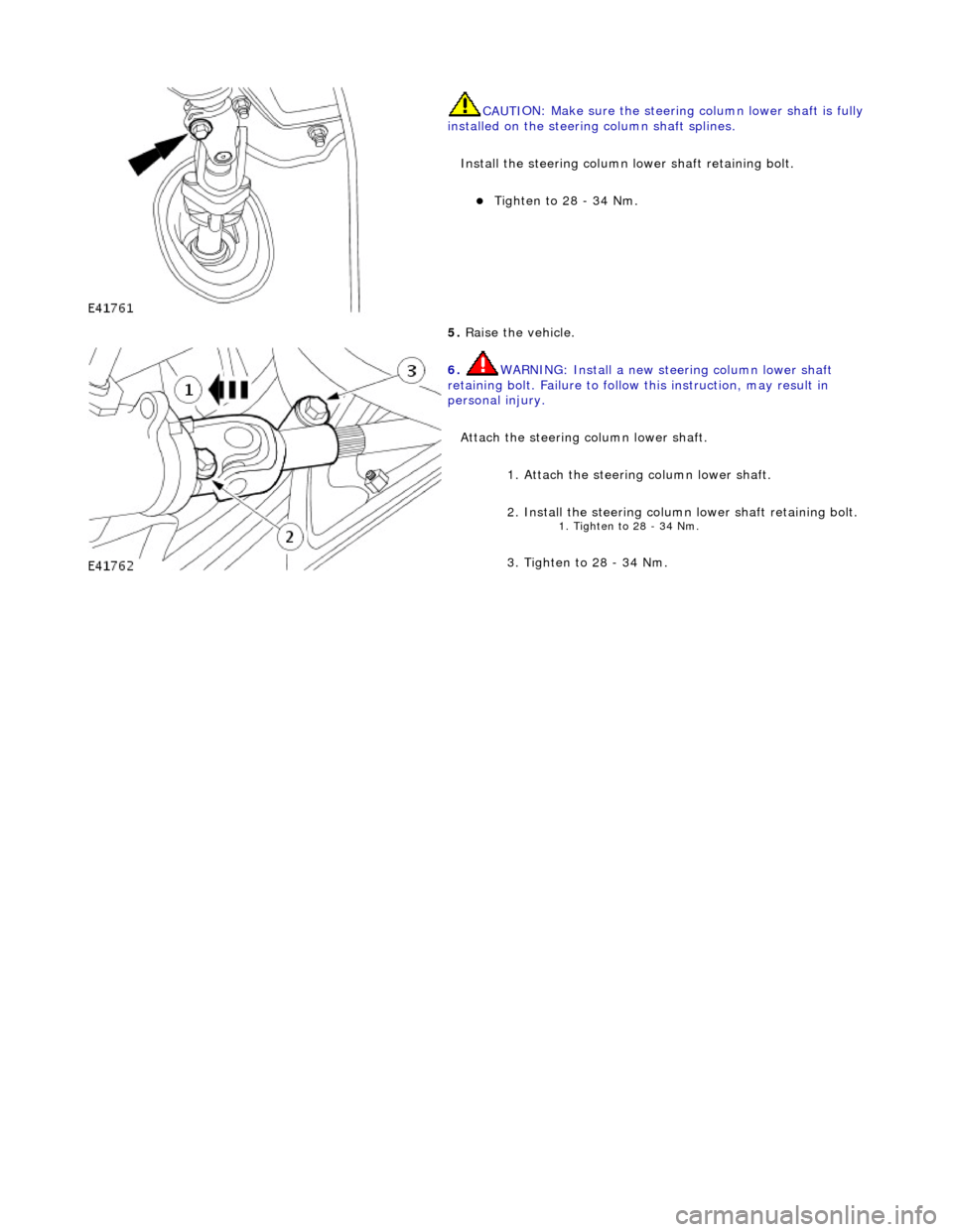
CAUTIO
N: Make sure the boot
is fully seated at the top
and bottom.
Attach the boot.
2. CAUTI O
NS:
Make sure the steering column lower shaft rolling element
is fully seated into the boot.
Make sure the boot is fully seated at the top and bottom.
Install the steering column lower shaft.
3. CAUTI O
NS:
Make sure the steering column lower shaft is fully installed
to the steering column shaft splines.
Make sure the steering column lower shaft rolling element
is fully seated into the boot.
Attach the steering column lower shaft.
4. WARNING: In stall a new stee ring column lower shaft
r
etaining bolt. Failure to follow this instruction, may result in
personal injury.
Page 513 of 2490

CAUTI
ON: Make sure the steering
column lower shaft is fully
installed on the steering column shaft splines.
Install the steering column lower shaft retaining bolt.
Ti
ghten to 28 - 34 Nm.
5.
R
aise the vehicle.
6. WARNING: In
stall a new stee
ring column lower shaft
retaining bolt. Failure to follow this instruction, may result in
personal injury.
Attach the steering column lower shaft. 1. Attach the steering column lower shaft.
2. Install the steering column lower shaft retaining bolt.
1. Tighten to 28 - 34 Nm
.
3
. Tighten to 28 - 34 Nm.
Page 516 of 2490

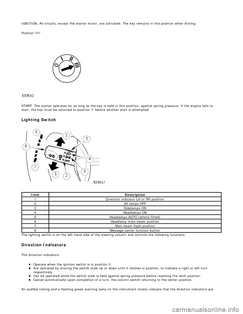
IGNITION.
All circuits, except the star
ter motor, are activated. The key rema ins in this position when driving.
Position 'III'
START. The starter operates for as long as the key is held in this position, ag ainst spring pressure. If the engine fails to
start, the key must be returned to position 'I' befo re another start is attempted.
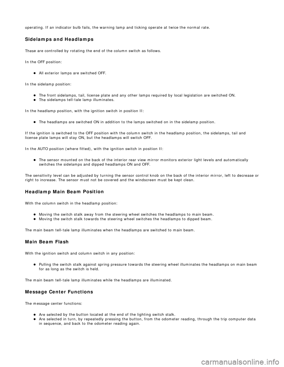
Lighting Switch
The li
ghting switch is on the left-h
and side of the steering column and controls the following functions.
Direction Indicators
The direction in
dicators:
Operate
when the ignition switch is in position II.
Are operat
ed by movi
ng the switch stalk up or down until it latches in position, to in
dicate a right or left turn
respectively.
Can be o p
erated while the switch stalk is held against
spring pressure before reaching the latch position.
Cancel
automatically upon completion of a turn, the
column switch returning to the center position.
An audible ticking and a flashing green warning lamp on the in strument cluster indicate that the direction indicators are
Ite
m
De
scr
iption
1D
i
rection indicator LH or RH position
2All lamps OFF
3Side
lamps ON
4Headlamps ON
5Headlamps AUT O
(where fitted)
6He
adlam
p main beam position
7Mai
n
beam flash position
8M
e
ssage center function button
Page 517 of 2490

o
perating. If an indicator bulb fails, the warning
lamp and ticking operate at twice the normal rate.
Sidelam
ps and Headlamps
Thes
e are controlled by rotating the end of the column switch as follows.
In the OFF position:
All
exterior lamps are switched OFF.
In the sidelamp position:
The front
sidelamps, tail, license plate and any other la
mps required by local legislation are switched ON.
The
sidelamps tell-tale lamp illuminates.
In the headlamp position, with the ignition switch in position II:
The h
eadlamps are switched ON in addition to the lamps switched on in the sidelamp position.
If the ignition is switched to the OFF position with the column switch in the headlamp position, the sidelamps, tail and
license plate lamps will stay ON, but the headlamps will switch OFF.
In the AUTO position (where fitted), with the ignition switch in position II:
Th
e sensor mounted on the back of the interior rear view
mirror monitors exterior light levels and automatically
switches the sidelamps and di pped headlamps ON and OFF.
The sensitivity level can be adjusted by turn ing the sensor control knob on the back of the interior mirror, left to decrease or
right to increase. The sensor must not be covered and the windscreen must be kept clean.
Headlamp Main Bea
m Position
Wi
th the column switch in
the headlamp position:
Movin
g the switch stalk away fro
m the steering wheel switches the headlamps to main beam.
Movin
g the switch stalk towards the steering wheel switches the headlamps to dipped beam.
The main beam tell-tale lamp illuminates when the headlamps are switched to main beam.
Ma
in Beam Flash
Wi
th the ignition switch and column switch in any position:
Pulling the
switch stalk agains
t spring pressure towards th e steering wheel illuminates the headlamps on main beam
for as long as the switch is held.
The main beam tell-tale lamp illuminates while the headlamps are illuminated.
M
essage Center Functions
T
he message center functions:
Are se
lected by the button located at the end of the lighting switch stalk.
Are se
lected in turn, by repeatedly pressing the button,
from the odometer reading, through the trip computer data
in sequence, and back to th e odometer reading again.