1998 JAGUAR X308 temperature sensor
[x] Cancel search: temperature sensorPage 1202 of 2490
St
eering wheel cassette reel short
circuit to ground
Cassette reel to ECM c
ircuit short
circuit to ground
CANC EL
switch failure (stuck ON)
Control.
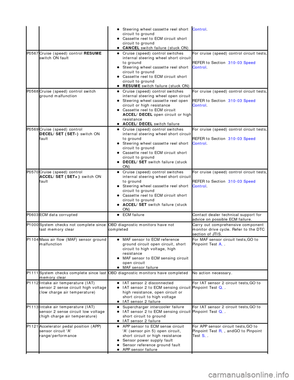
P0567Cruise (speed) contr
o
l
RESUME
switch ON fault
Cru i
se (speed) control switches
internal steering wheel short circuit
to ground
S t
eering wheel cassette reel short
circuit to ground
Cassette reel to ECM c
ircuit short
circuit to ground
RESUME s
witch failure (stuck ON)
For cru
i
se (speed) control circuit tests,
REFER to Section 310
-03 Sp
eed
Control.
P0568Cru
i
se (speed) control switch
ground malfunction
Cru i
se (speed) control switches
internal steering wheel open circuit
St
eering wheel cassette reel open
circuit or high resistance
Cassette reel to ECM ci
rcuit
ACCEL/DECEL open circuit or high
resistance
ACC E
L/DECEL
switch failure
For crui
se (speed) control circuit tests,
REFER to Section 310
-03 Sp
eed
Control.
P0569Cruise (speed) contr
o
l
DECEL/SET (SET-) switch ON
fault
Cru i
se (speed) control switches
internal steering wheel short circuit
to ground
S t
eering wheel cassette reel short
circuit to ground
Cassette reel to ECM c
ircuit short
circuit to ground
DECE
L/SET
switch failure (stuck
ON)
For cru i
se (speed) control circuit tests,
REFER to Section 310
-03 Sp
eed
Control.
P0570Cruise (speed) contro
l
ACCEL/SET (SET+) switch ON
fault
Crui
se (speed) control switches
internal steering wheel short circuit
to ground
S t
eering wheel cassette reel short
circuit to ground
Cassette reel to ECM c
ircuit short
circuit to ground
ACC E
L/SET
switch failure (stuck
ON)
For crui
se (speed) control circuit tests,
REFER to Section 310
-03 Sp
eed
Control.
P0603ECM dat
a
corrupted
ECM failu
r
e
Contact deal
er techni
cal support for
advice on possible ECM failure.
P1000 Sy
stem checks not complete since
last memory clear
O B
D diagnostic monitors have not
completed
Carr y out comprehensi
ve component
monitor drive cycle. Refer to the DTC
section of JTIS.
P1104Mass ai r fl
ow (MAF) sensor ground
malfunction
MAF sensor to EC
M reference
ground circuit open circuit, short
circuit to high voltage, high
resistance
MAF s
ensor to ECM sensing circuit
open circuit
MAF sensor fai
lure
For MAF
se
nsor circuit tests,GO to
Pinpoint Test A.
.
P1111Syst
em checks complete since last
memory clear
O B
D diagnostic monitors have completed
N
o
action necessary.
P1112In
t
ake air temperature (IAT)
sensor 2 sense circuit high voltage
(low charge air temperature)
IAT sensor 2 di sconnect
ed
IAT sensor 2
to ECM sensing circuit
high resistance, open circuit or
short circuit to high voltage
IAT se nsor 2 failure
F
or IAT sensor
2 circuit tests,GO to
Pinpoint Test Q.
.
P1113Int
ake air temperature (IAT)
sensor 2 sense circuit low voltage
(high charge air temperature)
Supercharger interco
oler failure
IAT se
nsor 2
to ECM sensing circuit
short circuit to ground
IAT se nsor 2 failure
F
or IAT sensor
2 circuit tests,GO to
Pinpoint Test Q.
.
P1121Accele
rator pedal position (APP)
sensor circuit 'A'
range/performance
A P
P sensor to ECM sense circuit
'A' (sensor pin 5) open circuit,
short circuit or high resistance
Sensor power su pply fault
Sensor r
e
ference ground fault
APP s
e
nsor failure
For APP
sen
sor circuit tests,GO to
Pinpoint Test R.
, andGO to Pinpoint
Test S.
.
Page 1208 of 2490
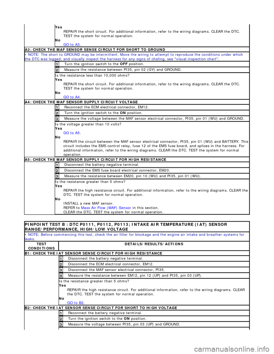
Yes
R
EPAIR the short circuit. For addi
tional information, refer to the wiring diagrams. CLEAR the DTC.
TEST the system for normal operation.
No GO to A3
.
A3: CHECK THE MAF SENSO
R SENS
E CIRCUIT FOR SHORT TO GROUND
• NO
TE: The short to GROUND may be intermittent. Move the
wiring to attempt to reproduce the conditions under which
the DTC was logged, and visually inspect the harness for any signs of chafing, see "visual inspection chart".
Turn the ignition swit
ch to the OFF
position.
1
Measure t
he resistance between PI35, pin 02 (GY) and GROUND.
2
Is t
he resistance less than 10,000 ohms?
Yes REPAIR the short circuit. For addi tional information, refer to the wiring diagrams. CLEAR the DTC.
TEST the system for normal operation.
No GO to A4
.
A4: CHEC K THE MA
F SENSOR SUPPLY CIRCUIT VOLTAGE
Re
conn
ect the ECM electrical connector, EM12.
1
Turn the ignition swi
t
ch to the ON
position.
2
Me
asure the voltage between the MAF sensor electrical connector, PI35, pin 01 (WU) and GROUND.
3
Is the vol
t
age greater than 10 volts?
Yes GO to A5
.
No
REP
AIR the circuit between the MAF sensor electric
al connector, PI35, pin 01 (WU) and BATTERY. This
circuit includes the EMS control rela y, fuse 12 of the EMS fuse board, and splices in the harness. For
additional information, refer to the wiring diagrams. CLEAR the DT C. TEST the system for normal
operation.
A5: CHECK THE MAF SENSO
R SUPPLY CIRCUIT FOR HIGH RESISTANCE
Di
sc
onnect the battery negative terminal.
1
Di
sc
onnect the EMS fuse board electrical connector, EM20.
2
Meas
ure t
he resistance between EM20,
pin 10 (WU) and PI35, pin 01 (WU).
3
Is the res
istance greater than 5 ohms?
Yes REPAIR the high resistance circuit. For additional information, refer to the wiring diagrams. CLEAR the
DTC. TEST the system for normal operation.
No INSTALL a new MAF sensor.
REFER to Mass Air Flow (MAF) Sensor
in this
section.
CLEAR the DTC. TEST the system for normal operation.
P INPOINT TES
T B : DTC P0111, P0112, P0113;
INTAKE AIR TEMPERATURE (IAT) SENSOR
RANGE/PERFORMANCE, HIGH/LOW VOLTAGE
•
NOTE: Before commencing this
test, check the air filter for blockage and the engine air intake and breather systems for
leaks.
TE S
T
CONDITIONS
D E
TAILS/RESULTS/ACTIONS
B1: CHECK
THE IAT SENSOR
SENS
E CIRCUIT FOR HIGH RESISTANCE
Disc
onnect the battery negative terminal.
1
D
i
sconnect the ECM electrical connector, EM12.
2
Di
sc
onnect the MAF sensor electrical connector, PI35.
3
Me
asure
the resistance between EM12, pin 12 (UP) and PI35, pin 03 (UP).
4
Is th
e res
istance greater than 5 ohms?
Yes REPAIR the high resistance circui t. For additional information, refer to the wiring diagrams. CLEAR
the DTC. TEST the system for normal operation.
No GO to B2
.
B2: CHECK
THE IAT SENSOR SENSE CIRCUIT FOR SHORT TO HIGH VOLTAGE
R
e
connect the battery negative terminal.
1
Turn the ignition swi
t
ch to the ON
position.
2
Measure the voltage between PI 35,
pin 03 (UP) and GROUND.
3
Page 1209 of 2490
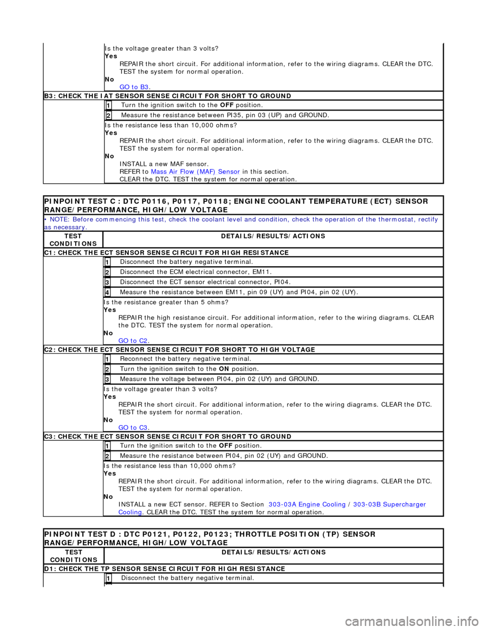
Is th
e voltage greater than 3 volts?
Yes REPAIR the short circuit. For addi tional information, refer to the wiring diagrams. CLEAR the DTC.
TEST the system for normal operation.
No GO to B3
.
B3: CHECK
THE IAT SENSOR SENS
E CIRCUIT FOR SHORT TO GROUND
Turn the ignition swi
tch to the OFF
position.
1
Meas
ure the resistance between PI35, pin 03 (UP) and GROUND.
2
Is
the resistance less than 10,000 ohms?
Yes
REPAIR the short circuit. For addi tional information, refer to the wiring diagrams. CLEAR the DTC.
TEST the system for normal operation.
No INSTALL a new MAF sensor.
REFER to Mass Air Flow (MAF) Sensor
in this section.
CLEAR the DTC. TEST the system for normal operation.
PI
NPOINT TEST C : DTC P0116, P0117, P0118
; ENGINE COOLANT TEMPERATURE (ECT) SENSOR
RANGE/PERFORMANCE, HIGH/LOW VOLTAGE
•
NOTE: Before commencing this
test, check the coolant level and condition, check the operation of the thermostat, rectify
as necessary.
TE
ST
CONDITIONS
D
ETAILS/RESULTS/ACTIONS
C1: CHECK THE ECT SEN
SOR SENS
E CIRCUIT FOR HIGH RESISTANCE
Di
sconnect the battery negative terminal.
1
D
isconnect the ECM electrical connector, EM11.
2
D
isconnect the ECT sensor electrical connector, PI04.
3
Meas
ure the resistance between EM11, pin 09 (UY) and PI04, pin 02 (UY).
4
Is th
e resistance greater than 5 ohms?
Yes
REPAIR the high resistance circui t. For additional information, refer to the wiring diagrams. CLEAR
the DTC. TEST the system for normal operation.
No GO to C2
.
C2: CHECK THE ECT SEN
SOR SENSE CI
RCUIT FOR SHORT TO HIGH VOLTAGE
R
econnect the battery negative terminal.
1
Turn the ignition swi
tch to the ON
position.
2
Meas
ure the voltage between PI04, pin 02 (UY) and GROUND.
3
Is th
e voltage greater than 3 volts?
Yes REPAIR the short circuit. For addi tional information, refer to the wiring diagrams. CLEAR the DTC.
TEST the system for normal operation.
No GO to C3
.
C3: CHECK THE ECT SEN
SOR SENSE CIRCUIT FOR SHORT TO GROUND
Turn the ignition swi
tch to the OFF
position.
1
Meas
ure the resistance between PI04, pin 02 (UY) and GROUND.
2
Is
the resistance less than 10,000 ohms?
Yes REPAIR the short circuit. For addi tional information, refer to the wiring diagrams. CLEAR the DTC.
TEST the system for normal operation.
No INSTALL a new ECT sensor. REFER to Section 303
-0
3A Engine Cooling
/
30
3
-0
3B Supercharger
Coo
ling
. CLEA
R the DTC. TEST the sy
stem for normal operation.
P
INPOINT TEST D : DTC P0121, P0122,
P0123; THROTTLE POSITION (TP) SENSOR
RANGE/PERFORMANCE, HIGH/LOW VOLTAGE
TE
ST
CONDITIONS
D
ETAILS/RESULTS/ACTIONS
D1: CHECK
THE TP SENSOR SENS
E CIRCUIT FOR HIGH RESISTANCE
Di
sconnect the battery negative terminal.
1
Page 1219 of 2490
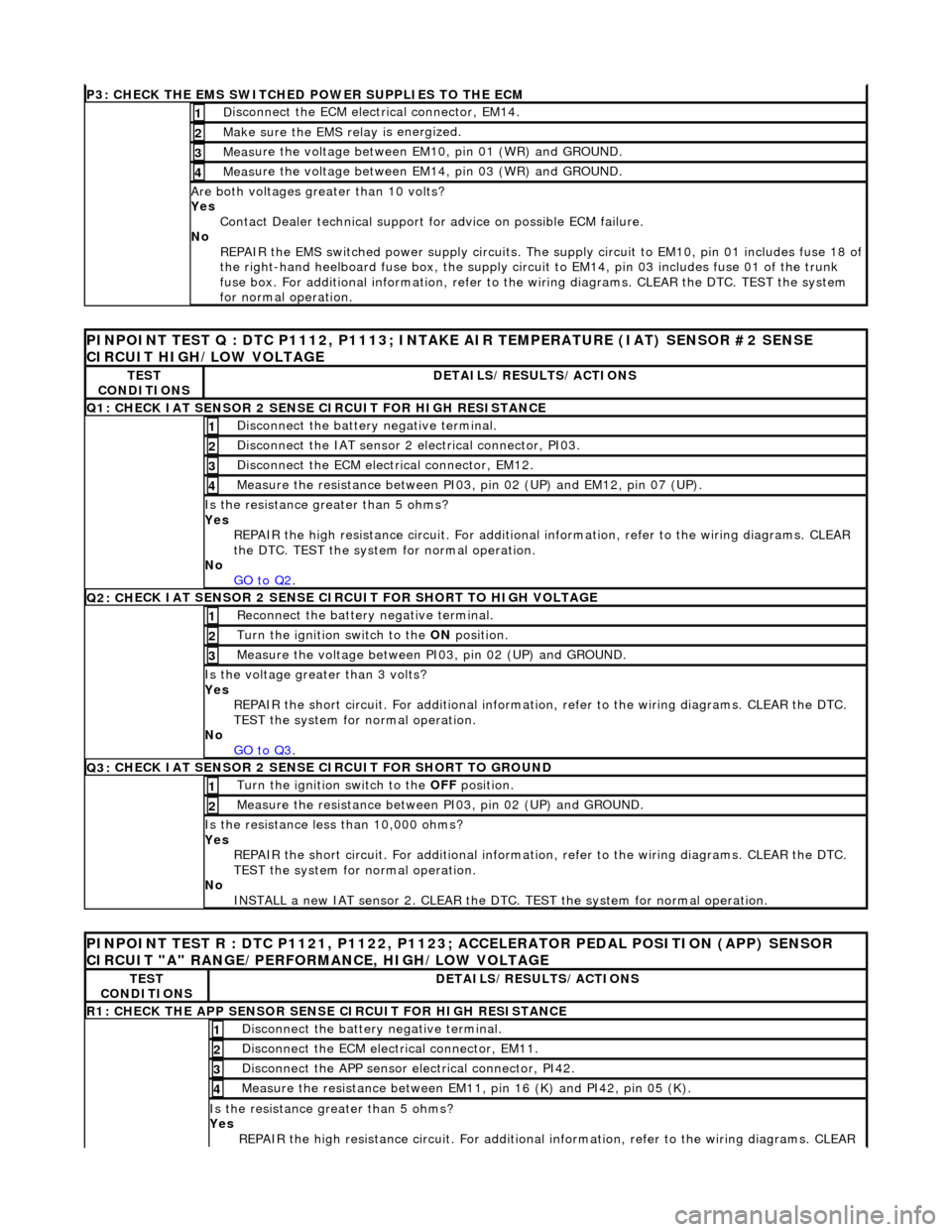
P3: CHECK
THE EMS SWITCHED
POWER SUPPLIES TO THE ECM
D
isconnect the ECM electrical connector, EM14.
1
Make sure the EMS re
lay i
s energized.
2
Meas
ure the voltage between EM10, pin 01 (WR) and GROUND.
3
Meas
ure the voltage between EM14, pin 03 (WR) and GROUND.
4
Are both
voltages greater than 10 volts?
Yes Contact Dealer technical support for advice on possible ECM failure.
No REPAIR the EMS switched power supply circuits. The su pply circuit to EM10, pin 01 includes fuse 18 of
the right-hand heelboard fuse box, the supply circuit to EM14, pin 03 includes fuse 01 of the trunk
fuse box. For additional information, refer to th e wiring diagrams. CLEAR the DTC. TEST the system
for normal operation.
PI
NPOINT TEST Q : DTC P1112, P1113; INTAKE
AIR TEMPERATURE (IAT) SENSOR #2 SENSE
CIRCUIT HIGH/LOW VOLTAGE
TE
ST
CONDITIONS
D
ETAILS/RESULTS/ACTIONS
Q1:
CHECK IAT SENSOR 2 SENSE CIRCUIT FOR HIGH RESISTANCE
Di
sconnect the battery negative terminal.
1
Di
sconnect the IAT sensor 2 electrical connector, PI03.
2
D
isconnect the ECM electrical connector, EM12.
3
Me
asure the resistance between PI03, pin 02 (UP) and EM12, pin 07 (UP).
4
Is th
e resistance greater than 5 ohms?
Yes REPAIR the high resistance circui t. For additional information, refer to the wiring diagrams. CLEAR
the DTC. TEST the system for normal operation.
No GO to Q2
.
Q2: CH
ECK IAT SENSOR 2 SENSE CIRC
UIT FOR SHORT TO HIGH VOLTAGE
R
econnect the battery negative terminal.
1
Turn the ignition swi
tch to the ON
position.
2
Measure the
voltage between PI
03, pin 02 (UP) and GROUND.
3
Is th
e voltage greater than 3 volts?
Yes REPAIR the short circuit. For addi tional information, refer to the wiring diagrams. CLEAR the DTC.
TEST the system for normal operation.
No GO to Q3
.
Q3:
CHECK IAT SENSOR 2 SENSE CIRCUIT FOR SHORT TO GROUND
Turn the ignition swi
tch to the OFF
position.
1
Meas
ure the resistance between PI03, pin 02 (UP) and GROUND.
2
Is
the resistance less than 10,000 ohms?
Yes REPAIR the short circuit. For addi tional information, refer to the wiring diagrams. CLEAR the DTC.
TEST the system for normal operation.
No INSTALL a new IAT sensor 2. CLEAR the DTC. TEST the system for normal operation.
P
INPOINT TEST R : DTC P1121, P1122, P1123;
ACCELERATOR PEDAL POSITION (APP) SENSOR
CIRCUIT "A" RANGE/PERFORMANCE, HIGH/LOW VOLTAGE
TE
ST
CONDITIONS
D
ETAILS/RESULTS/ACTIONS
R1: CHECK THE APP
SENSOR SENSE CIRCUIT FOR HIGH RESISTANCE
Di
sconnect the battery negative terminal.
1
D
isconnect the ECM electrical connector, EM11.
2
Di
sconnect the APP sensor electrical connector, PI42.
3
Meas
ure the resistance between EM11, pin 16 (K) and PI42, pin 05 (K).
4
Is th
e resistance greater than 5 ohms?
Yes REPAIR the high resistance circui t. For additional information, refer to the wiring diagrams. CLEAR
Page 1246 of 2490
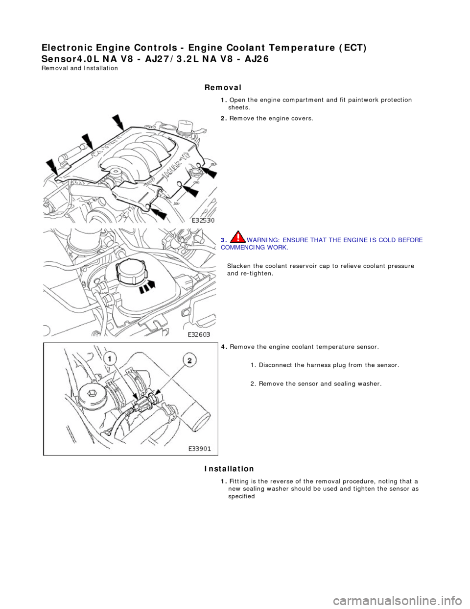
El
ectronic Engine Controls - En
gine Coolant Temperature (ECT)
Sensor4.0L NA V8 - AJ 27/3.2L NA V8 - AJ26
Remo
val and Installation
Remova
l
Installation
1. Op
en the engine compartment and fit paintwork protection
sheets.
2. Re
move the engine covers.
3. WA
RNING: ENSURE THAT THE ENGINE IS COLD BEFORE
COMMENCING WORK.
Slacken the coolant reservoir ca p to relieve coolant pressure
and re-tighten.
4. Remove t
he engine coolant temperature sensor.
1. Disconnect the harness plug from the sensor.
2. Remove the sensor and sealing washer.
1. Fitting is the reverse of the removal procedure, noting that a
new sealing washer should be us ed and tighten the sensor as
specified
Page 1248 of 2490
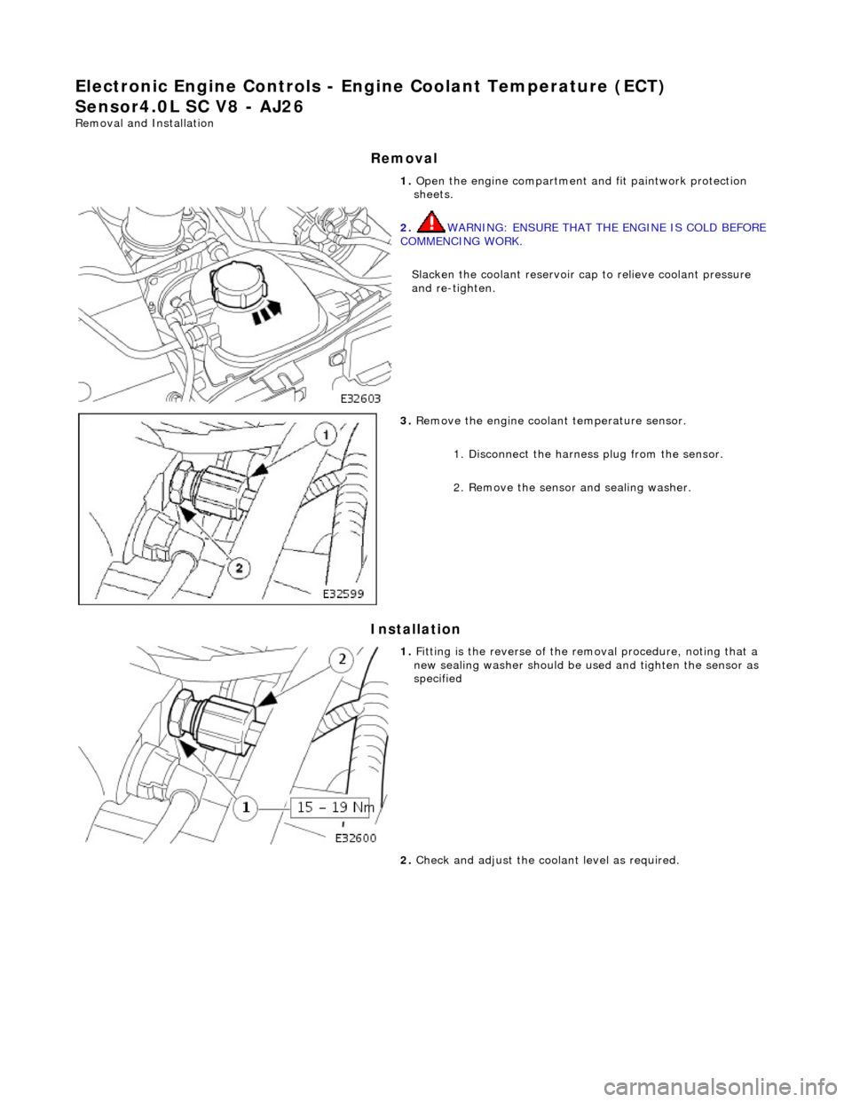
El
ectronic Engine Controls - En
gine Coolant Temperature (ECT)
Sensor4.0L SC V8 - AJ26
Re mo
val and Installation
Remova
l
Installation
1.
Op
en the engine compartment and fit paintwork protection
sheets.
2. WA
RNING: ENSURE THAT THE ENGINE IS COLD BEFORE
COMMENCING WORK.
Slacken the coolant reservoir ca p to relieve coolant pressure
and re-tighten.
3. Remove t
he engine coolant temperature sensor.
1. Disconnect the harness plug from the sensor.
2. Remove the sensor and sealing washer.
1. Fi
tting is the reverse of the removal procedure, noting that a
new sealing washer should be us ed and tighten the sensor as
specified
2. Check and adjust the cool ant level as required.
Page 1251 of 2490
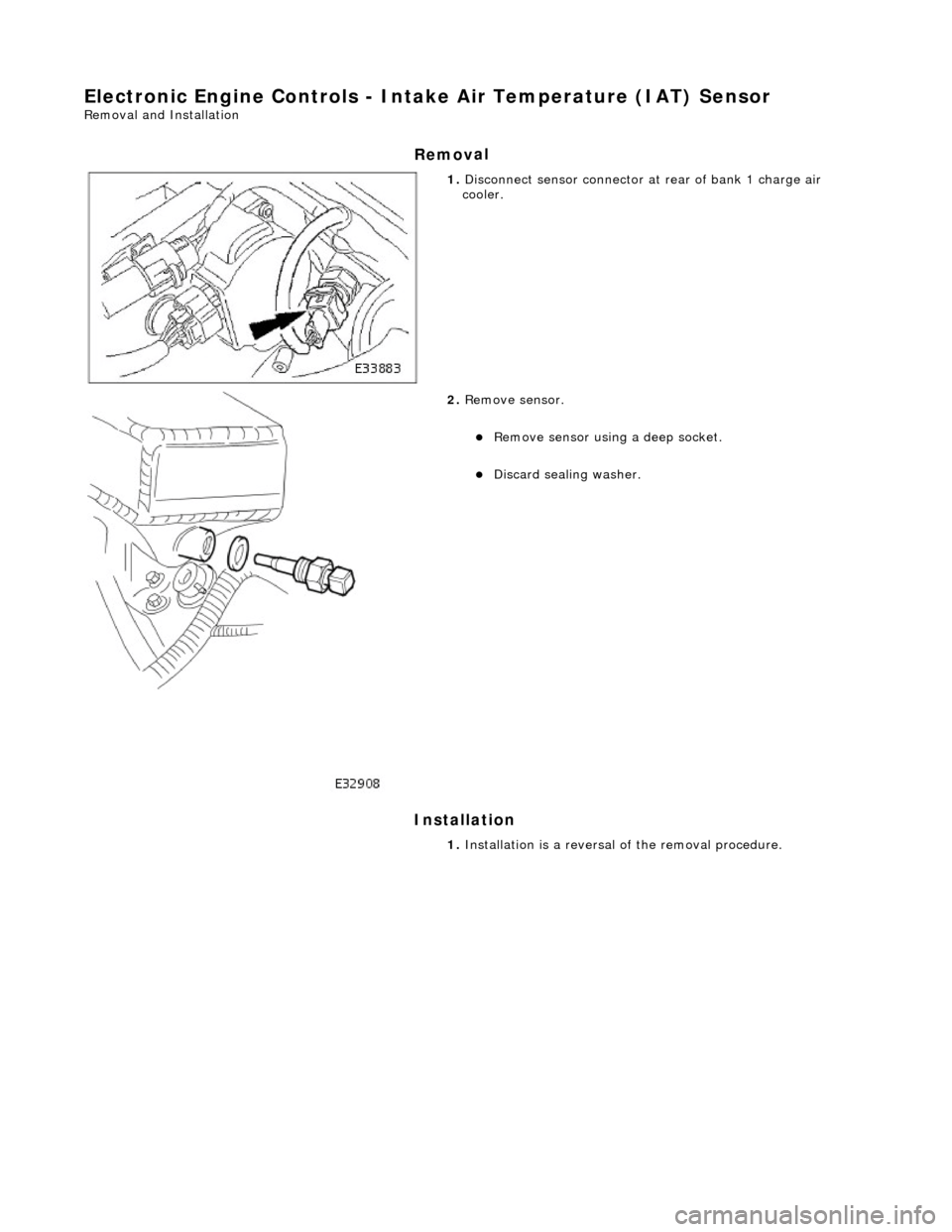
E
lectronic Engine Controls - Inta
ke Air Temperature (IAT) Sensor
Re
moval and Installation
Remov
al
Installation
1.
Di
sconnect sensor connector at
rear of bank 1 charge air
cooler.
2. Re
move sensor.
Re
move sensor using a deep socket.
Discard sealin
g washer.
1. Installation is a reversal of the removal procedure.
Page 1262 of 2490
Contains th
e hydraulic system pump.
Contains
th
e fluid temperature sensor.
The epicyclic geartrain:
Provi des fi
ve forward gears and Reverse.
Has
h
ydraulically actuated, multi-disk clutches, to select the required gear ratios.
Feature
s clutch-to-clutch operation to permit
gear shifts for uninterrupted power flow.
The electro-hydraulic control unit:
Is lo c
ated in the lower part of
the unit, within the fluid pan.
Is controlled
by the TCM (transmissio
n control module), and the manual selector valve which is cable operated.
Re
gulates the flow of fluid to the ge
artrain clutches via three solenoid-operated valv es and the manual selector
valve.
Has fi ve pressure
regulators for controll
ing fluid pressures within the system.
Is con
nected to the TCM via a 16-way connector mounted on
the left-hand side of the transmission casing. Refer to
Connector Pins Identification, Section 307-01A.
The hydraulic system pump:
Is l o
cated at the front of the transmission casing.
Is dri
v
en from the impeller hub,
pressurising the fluid whenever the engine is running.
Supplie
s fluid under pressure to the torq
ue converter, geartrain, electro-hydr aulic control unit and the lubrication
circuit.
D r
aws fluid from the fluid pa
n below the transmission casing, through a filter.
The rear extension housing:
Is bolt
ed to the rear of the transmission casing.
Provides the rear engine / transmi
ssion mo
unting point; refer to section 303-01.
Carrie
s the transmission output shaft oil seal.
Filled-for-l
i
fe Fluid System
The
transm
ission is 'filled for life' and
does not require fluid changes, except where extreme driving conditions prevail.
Routine level checking is not required and a dipstick is not pr ovided. A level / filler plug is fitted for level checking and
replenishment, following service actions; see 303-01 General Procedures.
Transmission Torque Converter