Page 1399 of 2490
Pin NumberCircuitCircuit Function
001n3 speed signal
002Pressure regulator MD signal
003n2 speed signal
004Temperature sensor
005Solenoid 1 <-> 2, 4 <-> 5
006Solenoid and pressure regulator +ve
007Speed sensor +ve
008Solenoid 2 <-> 3
009Solenoid 3 <-> 4
010Pressure regulator SD signal
011Torque converter solenoid
012Speed and temperature sensor ground
Page 1533 of 2490

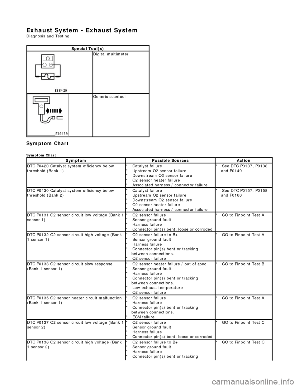
Exhaust System - Exhaust System
Diagnosis and Testing
Symptom Chart
Symptom Chart
Special Tool(s)
Digital multimeter
Generic scantool
SymptomPossible SourcesAction
DTC P0420 Catalyst system efficiency below
threshold (Bank 1)Catalyst failure
Upstream O2 sensor failure
Downstream O2 sensor failure
O2 sensor heater failure
Associated harness / connector failure
*
*
*
*
*See DTC P0137, P0138
and P0140
*
DTC P0430 Catalyst system efficiency below
threshold (Bank 2)Catalyst failure
Upstream O2 sensor failure
Downstream O2 sensor failure
O2 sensor heater failure
Associated harness / connector failure
*
*
*
*
*See DTC P0157, P0158
and P0160
*
DTC P0131 O2 sensor circuit low voltage (Bank 1
sensor 1)O2 sensor failure
Sensor ground fault
Harness failure
Connector pin(s) bent, loose or corroded
*
*
*
*GO to Pinpoint Test A
*
DTC P0132 O2 sensor circuit high voltage (Bank
1 sensor 1)O2 sensor failure to B+
Sensor ground fault
Harness failure
Connector pin(s) bent or tracking
between connections. O2 sensor failure
*
*
*
*
*GO to Pinpoint Test A
*
DTC P0133 O2 sensor circuit slow response
(Bank 1 sensor 1)O2 sensor heater failure / out of spec
Sensor ground fault
Harness failure
Connector pin(s) bent or tracking
between connections. Low exhaust temperature
O2 sensor failure
*
*
*
*
*
*GO to Pinpoint Test B
*
DTC P0135 O2 sensor heater circuit malfunction
(Bank 1 sensor 1)O2 sensor failure
Harness failure
Connector pin(s) bent or tracking
between connections. ECM failure
*
*
*
*GO to Pinpoint Test A
*
DTC P0137 O2 sensor circuit low voltage (Bank 1
sensor 2)O2 sensor failure
Sensor ground fault
Harness failure
Connector pin(s) bent, loose or corroded
*
*
*
*GO to Pinpoint Test C
*
DTC P0138 O2 sensor circuit high voltage (Bank
1 sensor 2)O2 sensor failure to B+
Sensor ground fault
Harness failure
Connector pin(s) bent or tracking
*
*
*
*GO to Pinpoint Test C
*
Page 1534 of 2490

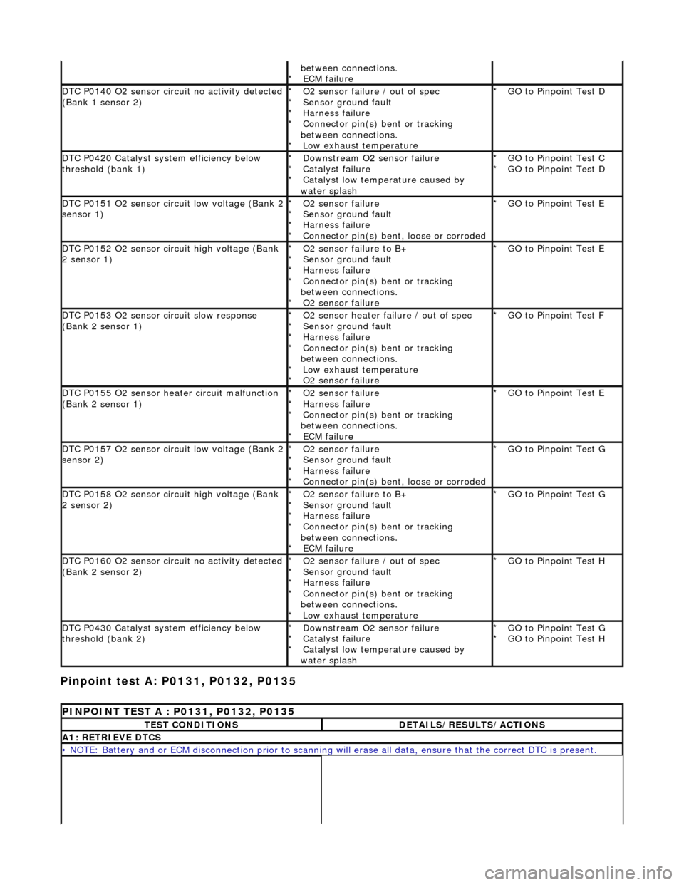
Pinpoint test A: P0131, P0132, P0135
between connections. ECM failure
*
DTC P0140 O2 sensor circuit no activity detected
(Bank 1 sensor 2)O2 sensor failure / out of spec
Sensor ground fault
Harness failure
Connector pin(s) bent or tracking
between connections. Low exhaust temperature
*
*
*
*
*GO to Pinpoint Test D
*
DTC P0420 Catalyst system efficiency below
threshold (bank 1)Downstream O2 sensor failure
Catalyst failure
Catalyst low temperature caused by
water splash
*
*
*GO to Pinpoint Test C
GO to Pinpoint Test D
*
*
DTC P0151 O2 sensor circuit low voltage (Bank 2
sensor 1)O2 sensor failure
Sensor ground fault
Harness failure
Connector pin(s) bent, loose or corroded
*
*
*
*GO to Pinpoint Test E
*
DTC P0152 O2 sensor circuit high voltage (Bank
2 sensor 1)O2 sensor failure to B+
Sensor ground fault
Harness failure
Connector pin(s) bent or tracking
between connections. O2 sensor failure
*
*
*
*
*GO to Pinpoint Test E
*
DTC P0153 O2 sensor circuit slow response
(Bank 2 sensor 1)O2 sensor heater failure / out of spec
Sensor ground fault
Harness failure
Connector pin(s) bent or tracking
between connections. Low exhaust temperature
O2 sensor failure
*
*
*
*
*
*GO to Pinpoint Test F
*
DTC P0155 O2 sensor heater circuit malfunction
(Bank 2 sensor 1)O2 sensor failure
Harness failure
Connector pin(s) bent or tracking
between connections. ECM failure
*
*
*
*GO to Pinpoint Test E
*
DTC P0157 O2 sensor circuit low voltage (Bank 2
sensor 2)O2 sensor failure
Sensor ground fault
Harness failure
Connector pin(s) bent, loose or corroded
*
*
*
*GO to Pinpoint Test G
*
DTC P0158 O2 sensor circuit high voltage (Bank
2 sensor 2)O2 sensor failure to B+
Sensor ground fault
Harness failure
Connector pin(s) bent or tracking
between connections. ECM failure
*
*
*
*
*GO to Pinpoint Test G
*
DTC P0160 O2 sensor circuit no activity detected
(Bank 2 sensor 2)O2 sensor failure / out of spec
Sensor ground fault
Harness failure
Connector pin(s) bent or tracking
between connections. Low exhaust temperature
*
*
*
*
*GO to Pinpoint Test H
*
DTC P0430 Catalyst system efficiency below
threshold (bank 2)Downstream O2 sensor failure
Catalyst failure
Catalyst low temperature caused by
water splash
*
*
*GO to Pinpoint Test G
GO to Pinpoint Test H
*
*
PINPOINT TEST A : P0131, P0132, P0135
TEST CONDITIONSDETAILS/RESULTS/ACTIONS
A1: RETRIEVE DTCS
• NOTE: Battery and or ECM disconnection prior to scanning wi
ll erase all data, ensure that the correct DTC is present.
Page 1546 of 2490
Connect the scan tool 1
Have the DTC(s) and freeze frame data been recorded?
Yes GO to B2
B2: CHECK FOR LOW EX HAUST TEMPERATURE
Check the engine and exhaust system for normal running
temperature 1
Is the engine and exhaust sy stem up to normal running
temperature?
Yes GO to B3
No Rectify possible leaking exhaust manifold / catalyst, general
causes of an over rich mixture and engine cooling system
operation. Test the system for correct operation.
GO to B8
B3: CHECK FOR O2 SENS OR HEATER CONTINUITY
Ignition switch to position 0 1
Disconnect EM021
Bracket on top of gearbox or Bulkhead rear of engine
2
With EM021 disconnected, measure the resistance between
EM021/001 and EM021/002. 3
Is the resistance between 4 and 10 OHM?
Yes
GO to B4
No Renew O2 sensor, reconnect plug(s).
GO to B8
B4: CHECK FOR O2 SENSOR FAILURE
Page 1570 of 2490
Connect the scan tool 1
Have the DTC(s) and freeze frame data been recorded?
Yes GO to D2
D2: CHECK FOR LOW EXHAUST TEMPERATURE
Check the engine and exhaust system for correct operation
and normal running temperature 1
Is the engine and exhaust system operating correctly and up to
normal running temperature?
Yes GO to D3
No Rectify leaking exhaust manifold / catalyst, general causes of
an over rich mixture and engine cooling system operation
and test the system for correct operation.
GO to D7
D3: CHECK FOR O2 SENSOR FAILURE
Run the engine for a period to warm the sensor and then
maintain a steady speed of approximately 2500 rpm. 1
Measure the voltage between EM022/001 and EM022/002. 2
Page 1598 of 2490
Connect the scan tool 1
Have the DTC(s) and freeze frame data been recorded?
Yes GO to F2
F2: CHECK FOR LOW EXHAUST TEMPERATURE
Check the engine and exhaust system for normal running
temperature 1
Is the engine and exhaust sy stem up to normal running
temperature?
Yes GO to F3
No Rectify possible leaking exhaust manifold / catalyst,
general causes of an over ri ch mixture and engine cooling
system operation. Test the sy stem for correct operation.
GO to F8
F3: CHECK FOR O2 SENSOR HEATER CONTINUITY
Ignition switch to position 0 1
Disconnect EM023
Bracket on top of gearbox or Bulkhead rear of engine
2
Measure the resistance between EM023/001 and
EM023/002. 3
Is the resistance between 4 and 10 OHM?
Yes
GO to F4
No Renew O2 sensor. Reconnect plug(s).
GO to F8
F4: CHECK FOR O2 SENSOR FAILURE
Page 1625 of 2490
Conne
ct the scan tool
1
Have the DTC(s) and fr
eeze
frame data been recorded?
Yes GO to H2
H2: CHECK
FOR LOW EXHAUST TEMPERATURE
Chec
k the engine and exhaust
system for correct operation
and normal running temperature
1
Is th
e engine and exhaust system operating correctly and up to
normal running temperature?
Yes GO to H3
No Rectify leaking exhaust manifold / catalyst, general causes of
an over rich mixture and engine cooling system operation and
test the system for correct operation.
GO to H7
H
3: CHECK FOR O2 SENSOR FAILURE
I
gnition switch to position 0
1
Di
sconnect EM024
Bracket on top o
f gearbox or
Bulkhead rear of engine
2
R
un the engine for a period to
warm the sensor and then
maintain a steady speed of approximately 2500 rpm.
3
W
ith EM024 disconnected, measure the voltage between
EM024/001 and EM024/002.
4
Is
the voltage between 600mV and 1.0 Volt?
Yes GO to H4
No Renew O2 sensor. Reconnect plug(s).
GO to H7
H
4: CHECK FOR O2 SENSOR FAILURE
Page 1785 of 2490

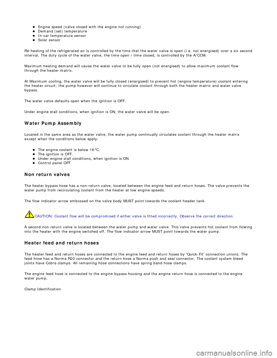
Engine speed (valve closed with the engine not running) Demand (set) temperature In-car temperature sensor Solar sensor
Re-heating of the refrigerated air is contro lled by the time that the water valve is open (i.e. not energised) over a six secon d
interval. The duty cycle of the water valve, the time open / time closed, is controlled by the A/CCM.
Maximum heating demand will cause the water valve to be fu lly open (not energised) to allow maximum coolant flow
through the heater matrix.
At Maximum cooling, the water va lve will be fully closed (energised) to prevent hot (engine temperature) coolant entering
the heater circuit; the pump however will continue to circulate coolant through both the heater matrix and water valve
bypass.
The water valve defaults open when the ignition is OFF.
Under engine stall conditions, when ignition is ON, the water valve will be open.
Water Pump Assembly
Located in the same area as the water valve, the water pump continually circulates coolant through the heater matrix
except when the conditions below apply:
The engine coolant is below 16°C. The ignition is OFF. Under engine stall conditions, when ignition is ON. Control panel OFF
Non return valves
The heater bypass hose has a non-return valve, located between the engine feed and return hoses. The valve prevents the
water pump from recirculating coolant fro m the heater at low engine speeds.
The flow indicator arrow embossed on the valve bo dy MUST point towards the coolant header tank.
CAUTION: Coolant flow will be compromi sed if either valve is fitted incorrectly. Observe the correct direction.
A second non-return valve is located betw een the water pump and water valve. This valve prevents hot coolant from flowing
into the heater with the engine switched off. The flow indicator arrow MUST point towards the water pump.
Heater feed and return hoses
The heater feed and return hoses are connected to the engine feed and return hoses by 'Quick-Fit' connection unions. The
feed hose has a Norma R20 connector and the return hose a Norma push and seal connector. The coolant system bleed
joints have Cobra clamps. All remaining hose connections have spring band hose clamps.
The engine feed hose is connected to the engine bypass hous ing and the engine return hose is connected to the engine
water pump.
Clamp Identification