Page 1275 of 2490

Automatic Transmission/Transaxle - 4.0L NA V8 - AJ27/3.2L NA V8 - AJ26
- Diagnostic Strategy
Diagnosis and Testing
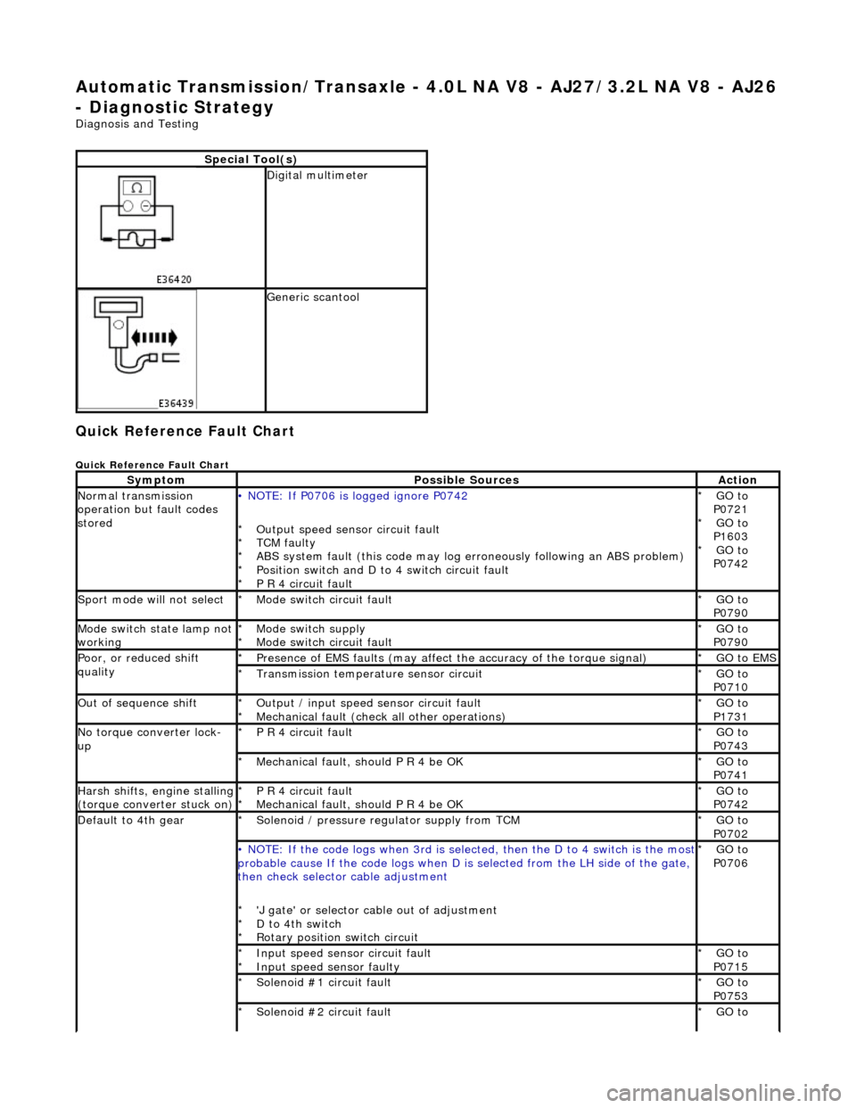
Quick Reference Fault Chart
Quick Reference Fault Chart
Special Tool(s)
Digital multimeter
Generic scantool
SymptomPossible SourcesAction
Normal transmission
operation but fault codes
stored• NOTE: If P0706 is logged ignore P0742
Output speed sensor circuit fault
TCM faulty
ABS system fault (this code may log er roneously following an ABS problem)
Position switch and D to 4 switch circuit fault
P R 4 circuit fault
*
*
*
*
*
GO to
P0721 GO to
P1603 GO to
P0742
*
*
*
Sport mode will not selectMode switch circuit fault
*GO to
P0790
*
Mode switch state lamp not
workingMode switch supply
Mode switch circuit fault
*
*GO to
P0790
*
Poor, or reduced shift
qualityPresence of EMS faults
(may affect the accuracy of the torque signal)
*GO to EMS *
Transmission temperature sensor circuit
*GO to
P0710
*
Out of sequence shiftOutput / input speed sensor circuit fault
Mechanical fault (check all other operations)
*
*GO to
P1731
*
No torque converter lock-
upP R 4 circuit fault
*GO to
P0743
*
Mechanical fault, should P R 4 be OK
*GO to
P0741
*
Harsh shifts, engine stalling (torque converter stuck on)P R 4 circuit fault
Mechanical fault, should P R 4 be OK
*
*GO to
P0742
*
Default to 4th gearSolenoid / pressure regulator supply from TCM
*GO to
P0702
*
• NOTE: If the code logs wh
en 3rd is selected, then the D to 4 switch is the most probable cause If the code logs when D is selected fro m the LH side of the gate,
then check selector cable adjustment
'J gate' or selector ca ble out of adjustment
D to 4th switch
Rotary position switch circuit
*
*
*GO to
P0706
*
Input speed sensor circuit fault
Input speed sensor faulty
*
*GO to
P0715
*
Solenoid #1 circuit fault
*GO to
P0753
*
Solenoid #2 circuit fault
*GO to
*
Page 1278 of 2490

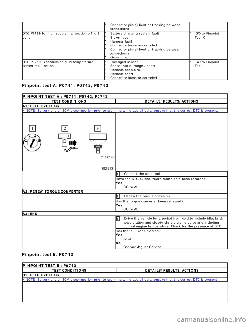
Pinpoint test A: P0741, P0742, P0743
Pinpoint test B: P0743
Connector pin(s) bent or tracking between
connections
*
DTC P1789 Ignition supply malfunction >7 < 9
voltsBattery charging system fault
Blown fuse
Harness fault
Connector loose or corroded
Connector pin(s) bent or tracking between
connections Ground fault
*
*
*
*
*
*GO to Pinpoint
Test K
*
DTC P0710 Transmission fluid temperature
sensor malfunctionDamaged sensor
Sensor out of range / short
Harness open circuit
Harness short
Connector loose or corroded
*
*
*
*
*GO to Pinpoint
Test L
*
PINPOINT TEST A : P0741, P0742, P0743
TEST CONDITIONSDETAILS/RESULTS/ACTIONS
A1: RETRIEVE DTCS
• NOTE: Battery and or ECM disconnection prior to scanning wi
ll erase all data, ensure that the correct DTC is present.
Connect the scan tool 1
Have the DTC(s) and freeze frame data been recorded?
Yes GO to A2
A2: RENEW TORQUE CONVERTER
Renew the torque converter 1
Has the torque converter been renewed?
Yes GO to A3
A3: END
Drive the vehicle for a period from cold to include idle, brisk
acceleration and steady state cruising up to and including
normal engine temperature. Check for the presence of DTC. 1
Has the fault code cleared?
Yes STOP
No Contact Jaguar Service
PINPOINT TEST B : P0743
TEST CONDITIONSDETAILS/RESULTS/ACTIONS
B1: RETRIEVE DTCS
• NOTE: Battery and or ECM disconnection prior to scanning wi ll erase all data, ensure that the correct DTC is present
Page 1362 of 2490
Automatic Transmission/Transaxle - 4.0L NA V8 - AJ27/3.2L NA V8 - AJ26
- Transmission Intern al Wiring Harness
In-vehicle Repair
Removal
• NOTE: The temperature sensor is integral with the internal harness.
1. Disconnect battery ground cable.
Remove the battery cover.
2. Raise the vehicle on a lift.
2. WARNING: TRANSMISSION FLUID MAY CAUSE
SEVERE BURNS, ENSURE THAT ALL SAFETY PROCEDURES
ARE OBSERVED.
Carefully remove the drain plug and drain the
transmission fluid.
3. Remove the twenty-two bolts which secure the fluid pan.
Remove the fluid pan and all tr aces of gasket material.
4. Remove the input speed sensor.
• NOTE: M5 fixing. 1. Release the screw which secures the input speed sensor bracket and pull the sensor clear.
Disconnect harness multiplug.
Page 1390 of 2490

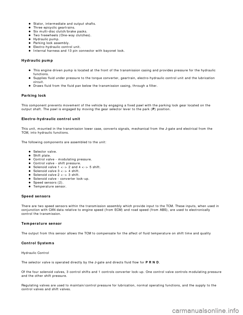
Stator, intermediate and output shafts. Three epicyclic geartrains. Six multi-disc clutch/brake packs. Two freewheels (One-way clutches). Hydraulic pump. Parking lock assembly. Electro-hydraulic control unit. Internal harness and 13 pin connector with bayonet lock.
Hydraulic pump
This engine driven pump is located at the front of the transmission casing and provides pressure for the hydraulic
functions.
Supplies fluid under pressure to the torq ue converter, geartrain, electro-hydraulic control unit and the lubrication
circuit.
Draws fluid from the fluid pa n below the transmission casing, through a filter.
Parking lock
This component prevents movement of th e vehicle by engaging a fixed pawl with the parking lock gear located on the
output shaft. The pawl is engaged by movi ng the gear selector lever to the park (P) position.
Electro-hydraulic control unit
This unit, mounted in the transmission lower case, converts signals, mechanical from the J-gate and electrical from the
TCM, into hydraulic functions.
The following components ar e assembled to the unit:
Selector valve. Shift plate. Control valve - modulating pressure. Control valve - shift pressure. Solenoid valve 1 <-> 2 and 4 <-> 5 shift. Solenoid valve 3 <-> 4 shift. Solenoid valve 2 <-> 3 shift. Solenoid valve - converter lock-up. Speed sensors (2). Temperature sensor.
Speed sensors
There are two speed sensors within the transmission assembly which provide input to the TCM. These inputs, when used in
conjunction with CAN data relative to engine speed (from ECM) and road speed (from ABS), are used to electronically
control the transmission.
Temperature sensor
The output from this sensor allows the TCM to compensate for the affect of fluid temperature on shift time and quality
Control Systems
Hydraulic Control
The selector valve is operated directly by the J-gate and directs fluid flow for P R N D.
Of the four solenoid valves, 3 control shifts and 1 controls converter lock-up. One control valve controls modulating pressure
and the other shift pressure.
Regulating valves are used to maintain/control pressure for lu brication, normal operating functions, and the supply to the
control valves and shift valves.
Page 1391 of 2490

In the event of a system fault, the TCM will adopt 'limp home' mode.
Electrical control
Refer to Section 307-01B.
Transmission Control Components
Transmission Control Module (TCM)
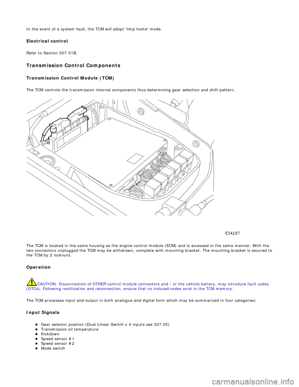
The TCM controls the transmission internal components thus determining gear selection and shift pattern.
The TCM is located in the same housing as the engine control module (ECM) and is accessed in the same manner. With the
two connectors unplugged the TCM may be withdrawn, complete with mounting bracket. The mounting bracket is secured to
the TCM by 2 locknuts.
Operation
CAUTION: Disconnection of OTHER contro l module connectors and / or the vehicle battery, may introduce fault codes
(DTCs). Following rectification and reconnection, ensu re that no induced codes exist in the TCM memory.
The TCM processes input and output in both analogue and di gital form which may be summarized in four categories:
Input Signals
Gear selector position (Dual Linear Switch x 4 inputs see 307.05) Transmission oil temperature Kickdown Speed sensor #1 Speed sensor #2 Mode switch
Page 1395 of 2490
and/or increased performance as appropriate.
Serial Communications Interfaces
Controller Area Network (CAN)
The TCM is an integral part of the CAN system which facilita tes the interchange of real-time data between control modules
and sensors; refer to 303-14 fo r a full description of CAN.
Transmission Pressure Regulators and Shift Solenoids Circuit Diagram
ItemPart NumberDescription
1—Transmission oil temperature sensor
2—Switch
3—Shift solenoid 1 <-> 2, 4 <-> 5
4—Shift solenoid 2 <-> 3
Page 1397 of 2490
Connector Pin Identity Chart for EM062
Connector Pin Identity Chart for CC008
Pin NumberCircuitCircuit Function
001Not used
002Kickdown SW
003Mode SW
025DLS position WO
026DLS position W1
027DLS position W2
028DLS position W3
029Ignition B+
030Power ground (common to DLS)
Pin NumberCircuitCircuit Function
012n2 speed signal
013Speed sensor +ve
014Solenoid 1 <-> 2 and 4 <-> 5
015Solenoid 3 <-> 4
016Solenoid 2 <-> 3
017Torque converter solenoid
033Speed and temperature sensor ground
034Temperature sensor
035n3 speed signal
036Pressure regulator Modulating signal
037Pressure regulator Shift signal
038Solenoid and pressure regulator +ve
040CAN link -ve
041CAN link +ve
Page 1398 of 2490
Connector Pin Identity Chart for GB001
Connector Pin Identity Chart for EM044
Pin NumberCircuitCircuit Function
001DLS position W3
002Power ground (common to TCM)
003Ignition B+
004Neutral (BPU)
005Park / neutral (ECM)
006DLS position W1
007DLS position WO
008DLS position W2
Pin NumberCircuitCircuit Function
001n3 speed signal
002Pressure regulator MD signal
003n2 speed signal
004Temperature sensor
005Not used
006Solenoid and pressure regulator +ve
007Speed sensor +ve
008Solenoid 2 <-> 3
009Solenoid 3 <-> 4
010Pressure regulator SD signal
011Torque converter solenoid
012Speed and temperature sensor ground
013Solenoid 1 <-> 2, 4 <-> 5