Page 625 of 2490
d
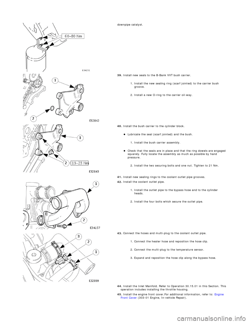
ownpipe catalyst.
39
.
Install new seals to the B-Bank VVT bush carrier.
1. Install the new sealing ring (scarf jointed) to the carrier bush groove.
2. Install a new O-ring to the carrier oil-way.
40
.
Install the bush carrier to the cylinder block.
Lu
bricate the seal (scarf
jointed) and the bush.
1. Install the bush carrier assembly.
Chec
k that the seals are
in place and that the ri ng dowels are engaged
squarely. Fully locate the assembly as much as possible by hand
pressure.
2. Install the two securing bolts and one nut. Tighten to 21 Nm.
41. Install new sealing rings to the coolant outlet pipe grooves.
42
.
Install the coolant outlet pipe.
1. Install the outlet pipe to the bypass hose and to the cylinder heads.
2. Install the four bolts which secure the outlet pipe.
43
.
Connect the hoses and multi-plug to the coolant outlet pipe.
1. Connect the heater hose and reposition the hose clip.
2. Connect the multi-plug to the temperature sensor.
3. Expand and reposition the hose clip along the bypass hose.
44. Install the Inlet Manifold. Refer to Operation 30.15.01 in this Section. This
operation includes installing the throttle housing.
45. Install the engine front cover.For additional information, refer to: Engine
Front Cover (303-01 Engi
ne, In-vehicle Repair).
Page 627 of 2490
E
ngine - Cylinder Head RH
In-ve
hicle Repair
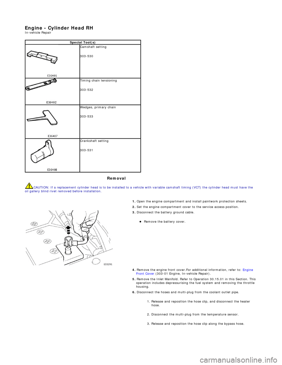
Remova
l
CAU
TION: If a replacement cylinder head is to be installed to a
vehicle with variable camshaft timing (VCT) the cylinder head m ust have the
oil gallery blind rivet removed before installation.
Spe
cial Tool(s)
Cams
haft setting
303-530
Ti
ming chain tensioning
303-532
Wedges, prim
ary chain
303-533
Cr
ankshaft setting
303-531
1.
Open the engine compartment and install paintwork protection sheets.
2. Set the engine compartment cover to the service access position.
3.
Disconnect the battery ground cable.
Re
move the battery cover.
4. Remove the engine front cover.For additional information, refer to: Engine
Front Cover (303-01 Engi
ne, In-vehicle Repair).
5. Remove the Inlet Manifold. Refer to Operation 30.15.01 in this Section. This operation includes depressurising the fuel system and removing the throttle
housing.
6. Disconnect the hoses and multi-plug from the coolant outlet pipe.
1. Release and reposition the hose clip, and disconnect the heater hose.
2. Disconnect the multi-plug from the temperature sensor.
3. Release and reposition the hose clip along the bypass hose.
Page 641 of 2490
2.
Connect the multi-plug to the temperature sensor.
3. Expand and reposition the hose clip along the bypass hose.
43. Install the Inlet Manifold. Refer to Operation 30.15.01 in this Section. This
operation includes installing the throttle housing.
44. Install the engine front cover.For additional information, refer to: Engine
Front Cover (303-01 Engi
ne, In-vehicle Repair).
45. Move the engine compartment cover from the service position and connect
the gas struts.
46. Remove the paint protection sheets and close the cover.
47. Connect the battery and install th e battery cover.For additional
information, refer to: Battery Connect
(414
-01 Battery, Mounting and
Cables, General Procedures).
Page 927 of 2490
A coola
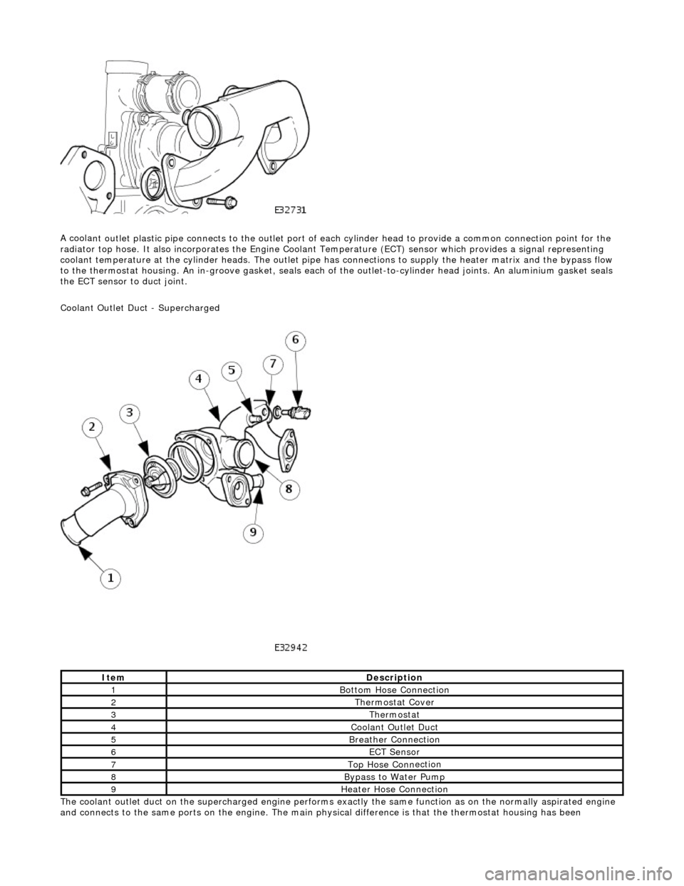
nt outlet plastic pipe connects to the outlet port of ea
ch cylinder head to provide a common connection point for the
radiator top hose. It also incorporates the Engine Coolant Te mperature (ECT) sensor which provides a signal representing
coolant temperature at the cylinder heads. The outlet pipe has connections to supply the heater matrix and the bypass flow
to the thermostat housing. An in-groove ga sket, seals each of the outlet-to-cylinder head joints. An aluminium gasket seals
the ECT sensor to duct joint.
Coolant Outlet Duct - Supercharged
The coolant outlet duct on the supercharged engine performs exactly the same function as on the normally aspirated engine
and connects to the same ports on the engine. The main physical difference is that the thermostat housing has been
ItemDe
scription
1Bottom
Hose Connection
2The
rmostat Cover
3The
rmostat
4Coolan
t Outlet Duct
5B
reather Connection
6ECT Se
nsor
7Top Hose Conn
ection
8Bypa
ss to Water Pump
9Hea
ter Hose Connection
Page 930 of 2490
Whe r
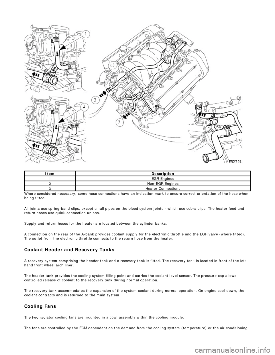
e considered necessary, some hose conn
ections have an indication mark to ensure correct orientation of the hose when
being fitted.
All joints use spring-band clips, except small pipes on the bleed system joints - which use cobra clips. The heater feed and
return hoses use quick-connection unions.
Supply and return hoses for the heater are located between the cylinder banks.
A connection on the rear of the A-bank provides coolant supply for the electronic throttle and the EGR valve (where fitted).
The outlet from the electronic throttle connects to the return hose from the heater.
Cool
ant Header and Recovery Tanks
A recovery system comp
rising the header tank
and a recovery tank is fitted. The recove ry tank is located in front of the left
hand front wheel arch liner.
The header tank provides the cooling system filling point and carries the coolant level sensor. The pressure cap allows
controlled release of coolant to the re covery tank during normal operation.
The recovery tank accommodates the expansion of the system coolant during normal operation. On engine cool-down, the
coolant contracts and is returned to the main system.
Coo lin
g Fans
The two
rad
iator cooling fans are mounted in
a cowl assembly within the cooling module.
The fans are controlled by the ECM dependent on the demand fr om the cooling system (temperature) or the air conditioning
ItemDescrip
tion
1EGR
E
ngines
2Non
-
EGR Engines
3Hea
ter Connections
Page 931 of 2490
s
ystem (pressure).
Outputs from the ECM control the radiator fans control module, located behind the left hand side of the bumper, to operate
the fans in the series mode (slow), paralle l mode (Fast) or Off modes. Hysteresis in the temperature and pressure switching
values prevents 'hun ting' between modes.
Under hot operating conditions, the fans may continue to operat e for some time after the engine has been switched off, but
will stop automatically when the coolant te mperature has been sufficiently reduced.
Engine Coolant Temperature Sensor (ECT) and ECM
The engine coolant temperature (ECT) sensor is located in the coolant outlet pipe and reacts to engine coolant temperature
changes, providing an input to the Engine Control Module (ECM). The sensor has a negative te mperature coefficient so that
the sensor resistance decrea ses as temperature rises.
Temperature / Resistance Relationship Graph
T
emperature / Resistance
Relationship Table
Page 932 of 2490
Engi
ne Coolant Temperature Sensor (ECT) - Circuit Diagram
Intercooler Pump Relay - Circuit Diagram
T emper
ature (°C)
No
mi
nal Resistance (kOHM)
-2
015 .0
4
05.7
4
202.45
401.15
600.
584
800.3
2
1000.
184
ItemPar
t
Number
De
scrip
tion
1—Eng
i
ne Coolant Temperature (ECT) Sensor
2—Eng
i
ne to EMS Harness Connector
3—EMS Con
trol Modu
le
Page 934 of 2490
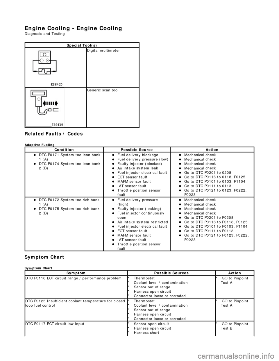
Engine Cooling - Engine Cooling
Diagn
osis and Testing
Related Faults / Codes
Adaptive
Fue
ling
Sym
p
tom Chart
Sy
m
ptom Chart
S
p
ecial Tool(s)
D
i
gital multimeter
Generi
c scan tool
Conditi
on
Possib
l
e Source
Acti
o
n
D
T
C P0171 System too lean bank
1 (A)
D T
C P0174 System too lean bank
2 (B)
Fuel delivery blockage Fu
el delivery pressure (low)
F
a
ulty injector (blocked)
Ai
r i
ntake system leak
F
u
el injector electrical fault
ECT sensor
faul
t
MAFM sensor fault IAT se
nsor fault
Thro
tt
le position sensor
fault
Mec hanica
l check
Mec
hanica
l check
Mec
hanica
l check
Mec
hanica
l check
Go t
o DTC P020
1 to 0208
Go t
o
DTC P0116 to 0118, P0125
Go t
o
DTC P0101 to 0103, P1104
Go t
o DTC P011
1 to 0113
Go t
o
DTC P0121 to 0123, P0222,
P0223
D T
C P0172 System too rich bank
1 (A)
D T
C P0175 System too rich bank
2 (B)
F u
el delivery pressure
(high)
F a
ulty injector (leaking)
F
u
el injector continuously
open
Ai r i
ntake system restricted
Fu
el injector electrical fault
ECT sensor
faul
t
MAFM sensor fault IAT sensor fault
Thrott
le position sensor
fault
Mec hanica
l check
Mec
hanica
l check
Mec
hanica
l check
Mec
hanica
l check
Go t
o DTC P020
1 to P0208
Go t
o
DTC P0116 to P0118, P0125
Go t
o
DTC P0101 to P0103, P1104
Go t
o DTC P011
1 to P0113
Go t
o
DTC P0121 to P0123, P0222,
P0223
Sy m
ptom
Possib
l
e Sources
Acti
o
n
D
T
C P0116 ECT circuit range / performance problem
Thermostat
Coo
l
ant level / contamination
Sensor out of range
Harness open circuit
Connector loose or corroded
*
*
*
*
*
GO to Pinpoint
Test A
*
D
T
C P0125 Insufficient coolant temperature for closed
loop fuel control
Thermostat
Coo l
ant level / contamination
Sensor out of range
Harness open circuit
Connector loose or corroded
*
*
*
*
*
GO to Pinpoint
Test A
*
D
T
C P0117 ECT circuit low input
Sensor o
p
en circuit
Harness open circuit
Harness short
*
*
*
GO to Pinpoint
Test B
*