Page 1360 of 2490
Automatic Transmission/Transaxle - 4.0L NA V8 - AJ27/3.2L NA V8 - AJ26
- Transmission Fluid Pan
In-vehicle Repair
Removal
Installation
1.
Raise the vehicle for access and drain the transmission fluid.
2. Remove the fluid pan.
Remove the twenty-two bolts.
3. Discard the fluid pan gasket and clean the mating faces.
4. Remove the magnets from the fluid pan.
Clean the magnets and refit them to the fluid pan.
1. Installation is th e reverse of the re moval procedure:
2. Tighten the fluid pan bolts to the specified torque figure.
3. Refill the transmission fluid. Refer to Operation 44.24.02.
Page 1361 of 2490
Automatic Transmission/Transaxle - 4.0L NA V8 - AJ27/3.2L NA V8 - AJ26
- Transmission Fluid Pan Gasket
In-vehicle Repair
Removal
Installation
1.
Raise the vehicle for access and drain the transmission fluid.
2. Remove the fluid pan.
Remove the twenty-two bolts.
3. Discard the fluid pan gasket and clean the mating faces.
4. Remove the magnets from the fluid pan.
Clean the magnets and refit them to the fluid pan.
1. Installation is th e reverse of the re moval procedure:
2. Tighten the fluid pan bolts to the specified torque figure.
3. Refill the transmission fluid. Refer to Operation 44.24.02.
Page 1362 of 2490
Automatic Transmission/Transaxle - 4.0L NA V8 - AJ27/3.2L NA V8 - AJ26
- Transmission Intern al Wiring Harness
In-vehicle Repair
Removal
• NOTE: The temperature sensor is integral with the internal harness.
1. Disconnect battery ground cable.
Remove the battery cover.
2. Raise the vehicle on a lift.
2. WARNING: TRANSMISSION FLUID MAY CAUSE
SEVERE BURNS, ENSURE THAT ALL SAFETY PROCEDURES
ARE OBSERVED.
Carefully remove the drain plug and drain the
transmission fluid.
3. Remove the twenty-two bolts which secure the fluid pan.
Remove the fluid pan and all tr aces of gasket material.
4. Remove the input speed sensor.
• NOTE: M5 fixing. 1. Release the screw which secures the input speed sensor bracket and pull the sensor clear.
Disconnect harness multiplug.
Page 1373 of 2490
Automatic Transmission/Transaxle - 4.0L NA V8 - AJ27/3.2L NA V8 - AJ26
- Turbine Shaft Speed (TSS) Sensor
In-vehicle Repair
Removal
1. Disconnect battery ground cable.
Remove the battery cover.
2. Raise the vehicle on a lift.
2. WARNING: TRANSMISSION FLUID MAY CAUSE
SEVERE BURNS, ENSURE THAT ALL SAFETY PROCEDURES
ARE OBSERVED.
Carefully remove the drain plug and drain the
transmission fluid.
3. Remove the twenty-two bolts which secure the fluid pan.
Remove the fluid pan and all tr aces of gasket material.
4. Remove the input speed sensor.
• NOTE: M5 fixing.
1. Release the screw which secures the input speed sensor bracket and pull the sensor clear.
5. Disconnect the multiplug from the speed sensor.
Page 1388 of 2490

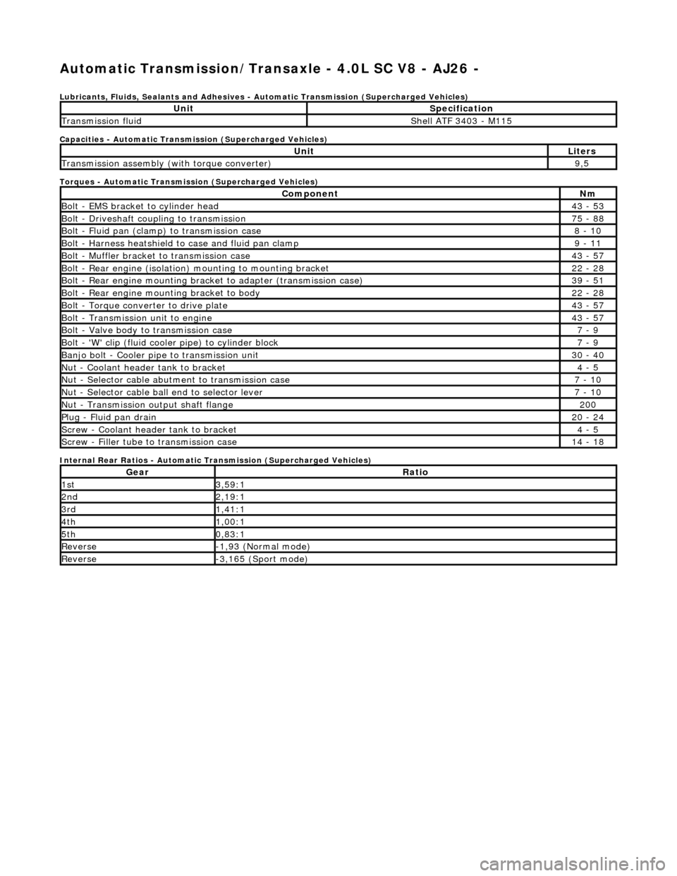
Automatic Transmission/Transaxle - 4.0L SC V8 - AJ26 -
Lubricants, Fluids, Sealants and Adhesives - Automatic Transmission (Supercharged Vehicles)
Capacities - Automatic Transmission (Supercharged Vehicles)
Torques - Automatic Transmission (Supercharged Vehicles)
Internal Rear Ratios - Automatic Transmission (Supercharged Vehicles)
UnitSpecification
Transmission fluidShell ATF 3403 - M115
UnitLiters
Transmission assembly (with torque converter)9,5
ComponentNm
Bolt - EMS bracket to cylinder head43 - 53
Bolt - Driveshaft coupling to transmission75 - 88
Bolt - Fluid pan (clamp) to transmission case8 - 10
Bolt - Harness heatshield to case and fluid pan clamp9 - 11
Bolt - Muffler bracket to transmission case43 - 57
Bolt - Rear engine (isolation) mounting to mounting bracket22 - 28
Bolt - Rear engine mounting brac ket to adapter (transmission case)39 - 51
Bolt - Rear engine mounting bracket to body22 - 28
Bolt - Torque converter to drive plate43 - 57
Bolt - Transmission unit to engine43 - 57
Bolt - Valve body to transmission case7 - 9
Bolt - 'W' clip (fluid cooler pipe) to cylinder block7 - 9
Banjo bolt - Cooler pipe to transmission unit30 - 40
Nut - Coolant header tank to bracket4 - 5
Nut - Selector cable abutment to transmission case7 - 10
Nut - Selector cable ball end to selector lever7 - 10
Nut - Transmission output shaft flange200
Plug - Fluid pan drain20 - 24
Screw - Coolant header tank to bracket4 - 5
Screw - Filler tube to transmission case14 - 18
GearRatio
1st3,59:1
2nd2,19:1
3rd1,41:1
4th1,00:1
5th0,83:1
Reverse-1,93 (Normal mode)
Reverse-3,165 (Sport mode)
Page 1441 of 2490
Automatic Transmission/Transaxle - 4.0L SC V8 - AJ26 - Transmission
Fluid Pan Gasket
In-vehicle Repair
Removal
• NOTE: This procedure will not remove re sidual fluid from the torque converter.
Installation
1. Disconnect the battery ground lead.
2. Raise the vehicle for access.
3. Drain the transmission fluid.
3. WARNING: TRANSMISSION FLUID MAY CAUSE
SEVERE BURNS, ENSURE THAT ALL SAFETY PROCEDURES
ARE OBSERVED AND THAT THE RECEPTACLE FOR WASTE
HAS SUFFICIENT CAPACITY.
Carefully remove the drain pl ug and discard the sealing
washer.
4. Remove the fluid pan.
• NOTE: The harness heatshield upper edge is retained by
a clip.
Remove the six bolts and clam ps which secure the fluid
pan to the transmission.
1. Installation is th e reverse of the re moval procedure.
Tighten the fluid pan retaining bolts to the specified torque figure.
2. Refit and tighten the drain plug to the specified torque figure.
Use a new sealing washer.
Page 1450 of 2490

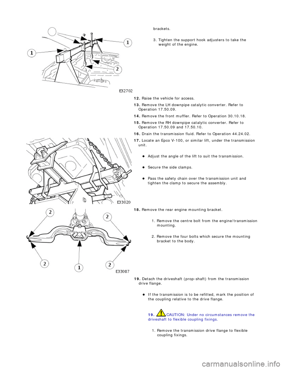
brackets.
3. Tighten the support hook adjusters to take the weight of the engine.
12. Raise the vehicle for access.
13. Remove the LH downpipe catalytic converter. Refer to
Operation 17.50.09.
14. Remove the front muffler. Re fer to Operation 30.10.18.
15. Remove the RH downpipe catalytic converter. Refer to
Operation 17.50.09 and 17.50.10.
16. Drain the transmission fluid. Refer to Operation 44.24.02.
17. Locate an Epco V-100, or sim ilar lift, under the transmission
unit.
Adjust the angle of the lift to suit the transmission.
Secure the side clamps.
Pass the safety chain over the transmission unit and
tighten the clamp to secure the assembly.
18. Remove the rear engine mounting bracket.
1. Remove the centre bolt from the engine/transmission
mounting.
2. Remove the four bolts which secure the mounting
bracket to the body.
19. Detach the driveshaft (prop- shaft) from the transmission
drive flange.
If the transmission is to be refitted, mark the position of
the coupling relative to the drive flange.
19. CAUTION: Under no circ umstances remove the
driveshaft to flexible coupling fixings.
1. Remove the transmission drive flange to flexible
coupling fixings.
Page 1733 of 2490

Fuel Tank and Li
nes - Fuel Pump
Re
moval and Installation
Remov
al
Installation
1.
WARNING: B
EFORE PROCEEDING, IT IS ESSENTIAL THAT
THE WARNING NOTES GIVEN IN SECTION 100-00 (UNDER THE
HEADING 'SAFETY PRECAUTIONS') ARE READ AND
UNDERSTOOD.
Remove the battery. For additional information, refer to Section
414
-0
1 Battery, Mounting and Cables
.
2.
Drain th
e fuel tank using a suitab
le suction pump/tanker. If the
On-board Refueling Vapour Recove ry (ORVR) system is fitted,
refer to Section 310
-00
Fuel System
- General
Information
.
3. R
emove the fuel tank. For addi
tional information, refer to Fuel
Tank
in this section.
4. Remove the fuel tank evaporativ e loss flange sealing ring. For
additional information, refer to Section 303
-13
.
5. R
emove fuel feed hose from tank.
U
sing special tool JD175, slacken fuel feed hose to tank
stub securing clip.
Di
sconnect hose from tank stub.
6. Remove fuel pump assembly.
R
elease bolt securing fuel
pump mounting bracket and
place assembly to front.
Slac
ken securing clip and disc
onnect hose from fuel pump.
R
emove link lead from fuel pump.
Re
move pump.
1. NOTE: Install new sealing ring to evaporative loss flange. For
additional information, refer to Section 303
-13
.
In
stallation is th
e reverse of the removal procedure.