Page 994 of 2490

Engine Cooling - Thermostat4.0L SC V8 - AJ26
Remo
val and Installation
Remov
a
l
Installation
1.
Op
en the engine compartment and fit paintwork protection
sheets.
2. Drain the radiator. Refer to Ge neral Procedures. Retain the
coolant drain tray in position to catch any spillage when
removing the outlet pipe.
3. Disc
onnect the bottom hose
from the coolant outlet pipe.
1. Release and reposi tion the hose clip.
2. Disconnect the bottom hose.
4. Re
move the thermostat from the outlet pipe.
1. Remove the three bolts which secure the thermostat cover to the outlet pipe.
2. Remove the thermostat cover, the thermostat and
the seal from the outlet pipe. Discard the seal.
1. Installation is th e reverse of the re moval procedure.
Use new seali
ng rings on th
e coolant outlet pipe and
thermostat housing.
The t he
rmostat ball valve must
locate in the recess in the
cover.
2. Tighten the thermostat cover bolts to 8-10 Nm.
3. Refill the cooling system as de scribed in General Procedures.
Page 995 of 2490

Engine Co
oling - Thermostat Housing
Cover4.0L NA V8 - AJ27/3.2L NA V8
- AJ26
Re
moval and Installation
Remov
al
Installation
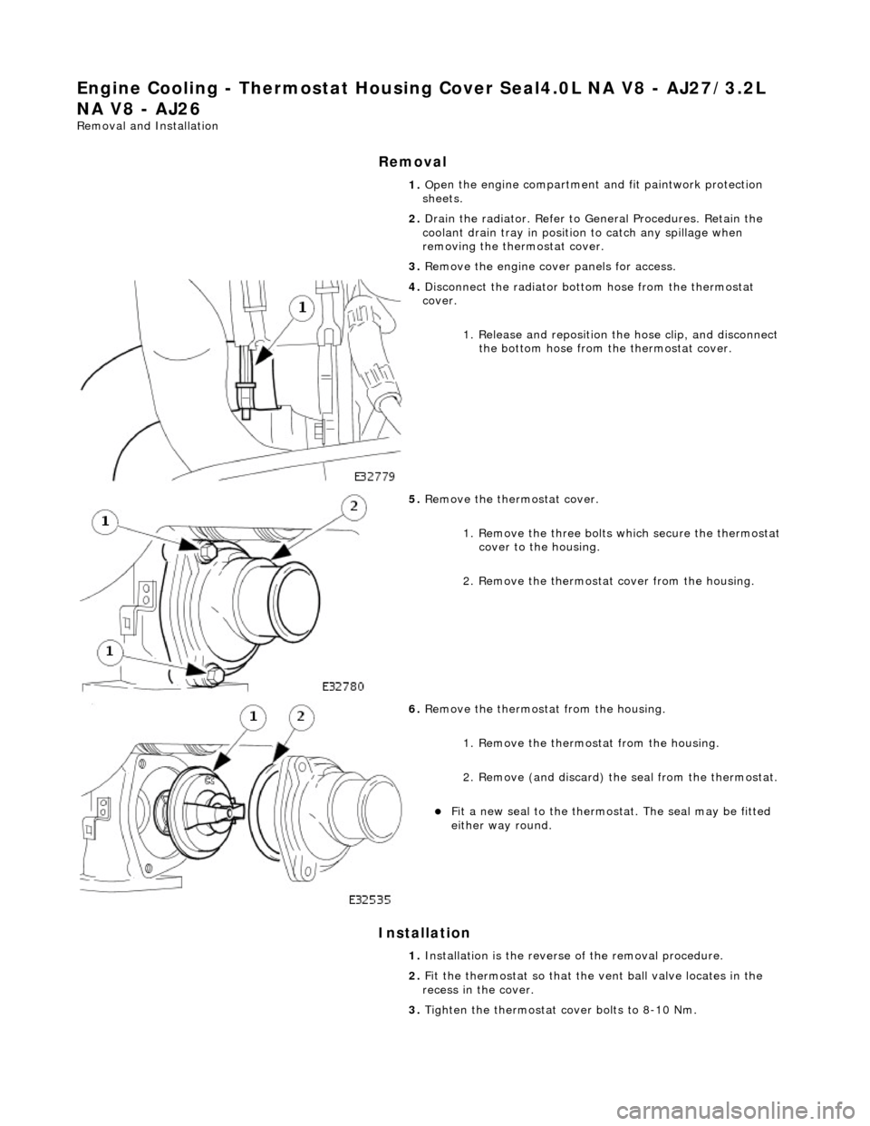
1. O
pen the engine compartment and fit paintwork protection
sheets.
2. Drain the radiator. Refer to Ge neral Procedures. Retain the
coolant drain tray in position to catch any spillage when
removing the thermostat cover.
3. Remove the engine cove r panels for access.
4. Di
sconnect the radiator bott
om hose from the thermostat
cover.
1. Release and reposition th e hose clip, and disconnect
the bottom hose from th e thermostat cover.
5. R
emove the thermostat cover.
1. Remove the three bolts which secure the thermostat cover to the housing.
2. Remove the thermostat cover from the housing.
6. R
emove the thermostat from the housing.
1. Remove the thermostat from the housing.
2. Remove (and discard) th e seal from the thermostat.
Fit a new seal to the
thermost
at. The seal may be fitted
either way round.
1. Installation is th e reverse of the re moval procedure.
2. Fit the thermostat so that the vent ball valve locates in the
recess in the cover.
3. Tighten the thermostat cover bolts to 8-10 Nm.
Page 997 of 2490

Engine Cooling - Thermostat Housing Cover4.
0L SC V8 - AJ26
Re
moval and Installation
Remov
al
Installation
1.
O
pen the engine compartment and fit paintwork protection
sheets.
2. Drain the radiator. Refer to Ge neral Procedures. Retain the
coolant drain tray in position to catch any spillage when
removing the outlet pipe.
3. Di
sconnect the bottom hose
from the coolant outlet pipe.
1. Release and reposi tion the hose clip.
2. Disconnect the bottom hose.
4. R
emove the thermostat from the outlet pipe.
1. Remove the three bolts which secure the thermostat cover to the outlet pipe.
2. Remove the thermostat cover, the thermostat and
the seal from the outlet pipe. Discard the seal.
1. Installation is th e reverse of the re moval procedure.
Use new
sealing rings on th
e coolant outlet pipe and
thermostat housing.
The t
hermostat ball valve must
locate in the recess in the
cover.
2. Tighten the thermostat cover bolts to 8-10 Nm.
3. Refill the cooling system as de scribed in General Procedures.
Page 998 of 2490

Engine Cooli
ng - Thermostat Housing
Cover Seal4.0L NA V8 - AJ27/3.2L
NA V8 - AJ26
Re mo
val and Installation
Remova
l
Installation
1. Op
en the engine compartment and fit paintwork protection
sheets.
2. Drain the radiator. Refer to Ge neral Procedures. Retain the
coolant drain tray in position to catch any spillage when
removing the thermostat cover.
3. Remove the engine cove r panels for access.
4. Disc
onnect the radiator bott
om hose from the thermostat
cover.
1. Release and reposition th e hose clip, and disconnect
the bottom hose from th e thermostat cover.
5. Re
move the thermostat cover.
1. Remove the three bolts which secure the thermostat cover to the housing.
2. Remove the thermostat cover from the housing.
6. Re
move the thermostat from the housing.
1. Remove the thermostat from the housing.
2. Remove (and discard) th e seal from the thermostat.
Fit a new seal to the
thermostat. Th
e seal may be fitted
either way round.
1. Installation is th e reverse of the re moval procedure.
2. Fit the thermostat so that the vent ball valve locates in the
recess in the cover.
3. Tighten the thermostat cover bolts to 8-10 Nm.
Page 1000 of 2490

Engine Cooli
ng - Thermostat Housin
g Cover Seal4.0L SC V8 - AJ26
Remo
val and Installation
Remov
a
l
Installation
1.
Op
en the engine compartment and fit paintwork protection
sheets.
2. Drain the radiator. Refer to Ge neral Procedures. Retain the
coolant drain tray in position to catch any spillage when
removing the outlet pipe.
3. Disc
onnect the bottom hose
from the coolant outlet pipe.
1. Release and reposi tion the hose clip.
2. Disconnect the bottom hose.
4. Re
move the thermostat from the outlet pipe.
1. Remove the three bolts which secure the thermostat cover to the outlet pipe.
2. Remove the thermostat cover, the thermostat and
the seal from the outlet pipe. Discard the seal.
1. Installation is th e reverse of the re moval procedure.
Use new seali
ng rings on th
e coolant outlet pipe and
thermostat housing.
The t he
rmostat ball valve must
locate in the recess in the
cover.
2. Tighten the thermostat cover bolts to 8-10 Nm.
3. Refill the cooling system as de scribed in General Procedures.
Page 1001 of 2490

Engine Cooling - Water Pump4.0L NA V8 - AJ27/ 3.2L NA V8 - AJ26
Re
moval and Installation
Remov
al
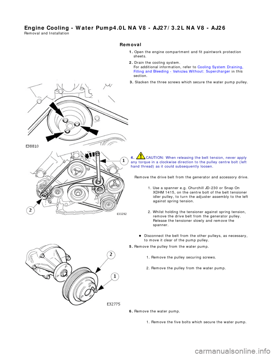
1.
O
pen the engine compartment and fit paintwork protection
sheets.
2. Drain the cooling system.
For additional information, refer to Cooling System Draining,
Fillin
g and Bleeding
- Vehicles W
ithout: Supercharger
in
this
section.
3. Sl
acken the three screws which
secure the water pump pulley.
4. CAUTI
ON: When releasing the
belt tension, never apply
any torque in a clockwise direction to the pulley ce ntre bolt (left
hand thread) as it could subsequently loosen.
Remove the drive belt from the generator and accessory drive.
1. Use a spanner e.g. Churchill JD-230 or Snap On XDHM 1415, on the centre bo lt of the belt tensioner
idler pulley, to turn the adju ster assembly to the left
against spring tension.
2. Whilst holding the tensioner against spring tension, remove the drive belt from the generator pulley.
Release the tensioner sl owly and remove the
spanner.
D
isconnect the belt from the ot
her pulleys, as necessary,
to move it clear of the pump pulley.
5. Re
move the pulley from the water pump.
1. Remove the pulley securing screws.
2. Remove the pulley from the water pump.
6. Remove the water pump.
1. Remove the five bolts wh ich secure the water pump.
Page 1004 of 2490

Engine Cooling - Water Pump4.0L SC V8 - AJ26
Remo
val and Installation
Remov
a
l
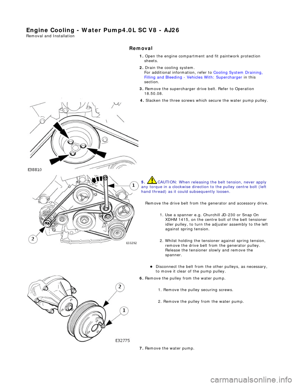
1.
Op
en the engine compartment and fit paintwork protection
sheets.
2. Drain the cooling system.
For additional information, refer to Cooling System Draining,
Filling and Bleedin
g
- Vehicles With
: Supercharger in this
section.
3. Remove the supercharger driv e belt. Refer to Operation
18.50.08.
4. Slacken the three screws whi
ch
secure the water pump pulley.
5. CAUTIO
N: When releasing the
belt tension, never apply
any torque in a clockwise direction to the pulley ce ntre bolt (left
hand thread) as it could subsequently loosen.
Remove the drive belt from the generator and accessory drive.
1. Use a spanner e.g. Churchill JD-230 or Snap On XDHM 1415, on the centre bo lt of the belt tensioner
idler pulley, to turn the adju ster assembly to the left
against spring tension.
2. Whilst holding the tensioner against spring tension, remove the drive belt from the generator pulley.
Release the tensioner sl owly and remove the
spanner.
Di
sconnect the belt from the ot
her pulleys, as necessary,
to move it clear of the pump pulley.
6. Remove t
he pulley from the water pump.
1. Remove the pulley securing screws.
2. Remove the pulley from the water pump.
7. Remove the water pump.
Page 1120 of 2490

Intake Air Distribution and Filtering - Charge Air Cooler LH
Remo
val and Installation
Remov
a
l
Installation
1. Disc onne
ct battery ground cable (IMPORTANT, see SRO
86.15.19 for further information).
2. Drain radiator coolant; refer to 26.10.01.
3. Remove air cleaner cover / intake assembly; refer to 19.10.30.
4. Remove throttle body; refer to 19.70.04.
5. Remove exhaust gas re-circulation valve (EGR) if installed;
refer to 17.45.01.
6. Remove throttle intake elbo w; refer to (SC) 19.70.28.
7. Remove supercharger outlet duct; refer to 18.50.16.
8. Remove coolant outlet pipe; refe r to operation (SC) 26.31.08.
9. Remove supercharger drive belt; refer to 18.50.08.
10. Remove supercharger; refer to operation 18.50.15.
11. Detach engine harness retaining clip from rear of charge air
cooler.
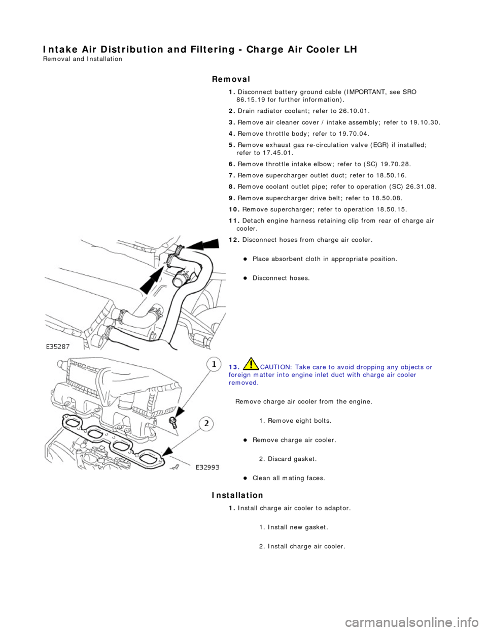
12. Di
sconnect hoses from charge air cooler.
Pla
ce absorbent cloth in appropriate position.
Di
sc
onnect hoses.
13 .
CAUTI
ON: Take care to avoi
d dropping any objects or
foreign matter into engine inle t duct with charge air cooler
removed.
Remove charge air cooler from the engine.
1. Remove eight bolts.
Remove charge air cooler.
2
. Discard gasket.
Cle
a
n all mating faces.
1.
Install ch
arge air
cooler to adaptor.
1. Install new gasket.
2. Install charge air cooler.