1998 JAGUAR X308 drain bolt
[x] Cancel search: drain boltPage 1738 of 2490
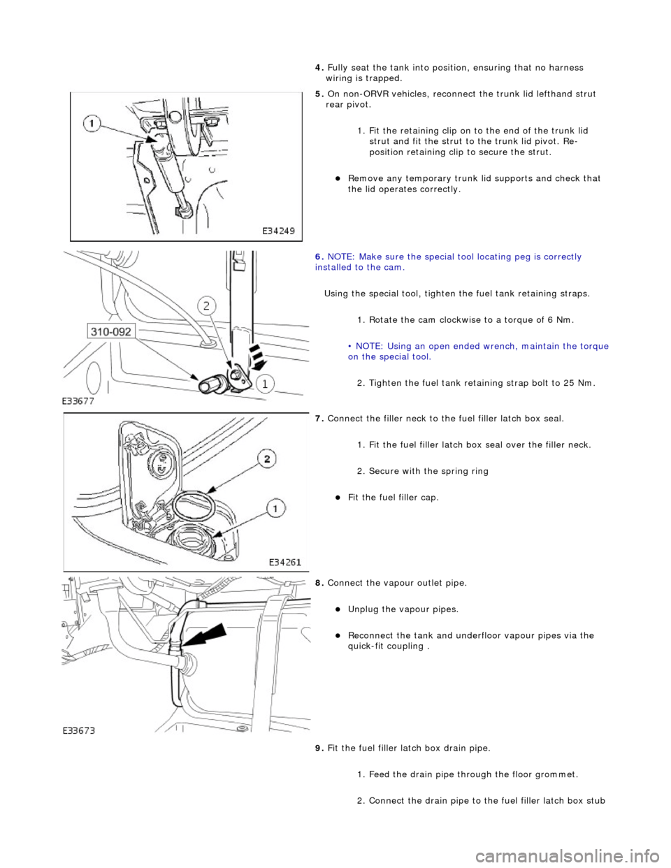
4. Full
y seat the tank into positi
on, ensuring that no harness
wiring is trapped.
5. On non-
ORVR vehicles, reconnec
t the trunk lid lefthand strut
rear pivot.
1. Fit the retaining clip on to the end of the trunk lid strut and fit the strut to the trunk lid pivot. Re-
position retaining clip to secure the strut.
Re
move any temporary trunk lid supports and check that
the lid operates correctly.
6. NOTE
: Make sure the special tool locating peg is correctly
installed to the cam.
Using the special tool, tighten the fuel tank retaining straps.
1. Rotate the cam clockwise to a torque of 6 Nm.
• NOTE: Using an open ended wrench, maintain the torque
on the special tool.
2. Tighten the fuel tank reta ining strap bolt to 25 Nm.
7. Connect the fi
ller neck to the fuel filler latch box seal.
1. Fit the fuel filler latch box seal over the filler neck.
2. Secure with the spring ring
F i
t the fuel filler cap.
8. Connect the vapour outlet pip
e.
Unplug the v
a
pour pipes.
Reconn
ect th
e tank and underfloor vapour pipes via the
quick-fit coupling .
9. Fit the fuel filler latch box drain pipe.
1. Feed the drain pipe th rough the floor grommet.
2. Connect the drain pipe to the fuel filler latch box stub
Page 1788 of 2490
Heating and Ventilation - Heater Core and Evaporator Core Housing
Removal and Installation
Removal
1. Disconnect battery ground cable (IMPORTANT, see SRO
86.15.19 for further information).
2. Recover refrigerant from air co nditioning system; refer to
82.30.30.
3. Drain radiator coolant only; refer to 26.10.01 or (SC)
26.10.01.
4. Remove instrument panel for access, refer to 76.46.01.
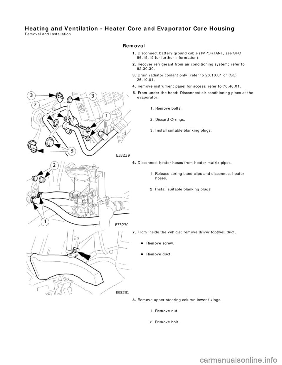
5. From under the hood: Disconnect air conditioning pipes at the
evaporator.
1. Remove bolts.
2. Discard O-rings.
3. Install suitable blanking plugs.
6. Disconnect heater hoses from heater matrix pipes.
1. Release spring band clips and disconnect heater hoses.
2. Install suitable blanking plugs.
7. From inside the vehicle: re move driver footwell duct.
Remove screw.
Remove duct.
8. Remove upper steering column lower fixings.
1. Remove nut.
2. Remove bolt.
Page 2022 of 2490
Body closures
Each front and rear door consists of a welded, mild steel inner frame and an outer panel. The outer panel is welded to the
waist rail and cheater of the inner frame, then bonded and clinched to fo rm the door assembly. Cosmetic PVC bead is
applied to all clinch joints. Sp onge rubber seals are mounted on the doors. Inte rnal insulation is provided by a foam water
shedder attached to the door by double-sided adhesive tape.
The door aperture B/C posts are reinforced over their full height to fully satisfy all forthcoming European and Federal side
impact legislation. The hood consists of one piece inner and outer panels clinched and bonded together, with cosmetic bead
PVC sealant applied to all clinch joints. Th e hood pivots at the front on two hinges each secured by bolts to the hood front
underside and the BIW front upper crossmem ber. Two gas struts secured to the hood by pivot pins and snap-on couplings,
support the hood in the open position. A full width insulating pad is secured by screws to the underside of the hood. A
sponge rubber tubular seal is mounted tran sversely towards the front of the hood underside. The trunk lid is of similar
construction to the hood, consisting of inner and outer pa nels clinched and bonded together and PVC bead sealed.
Incorporating a removable moulded liner and two trunk illuminati on lights, the trunk lid is supported when open, by two gas
struts, each secured to the inner wheel arch and trunk hinge by snap fittin gs. For some markets, a warning triangle is
attached to a bracket on the trunk lid underside and is retained in the open position by a rubber block.
Fascia
One-piece slush-moulded fascia on inject ion moulded armature and steel cross-rail reinforcement. Fascia support brackets
set with BIW to achieve close tolerance fit of fascia to bo dy eliminate necessity for adjustment following removal and
installation..
Fuel Filler Flap
The fuel filler comprising a hinged flap attached to the body decking panel by tw o nuts, incorporates a rubber buffer, snap-
in striker, hinge spring and fuel cap stowage magnet. The rubber fuel bowl moulding is attached via a steel armature to the
body reinforcement panel by five M5 nuts and is retained at the filler neck by a clip. The mating drain tube is fitted with an
internal filter. The fuel filler flap latch mechanism attached to the fuel bowl armatu re by two M5 nuts, includes a locking pin
and actuator which are both se rviceable items. The latch actuator operates independently from the central locking system;
it is driven directly by the se curity and locking control module. Locking of the fuel filler flap is achi eved only by operation of
the key or by the remote rf transmitter.
Seating
All front seats are equipped with electric height adjustment. In addition, both seats are available with manual or power
forward and rearward adjustment, manual or power operated headrest adjustment, 12 way electric adjustment, memory
controlled 12 way seat adjustment and integral seat heating. A side air bag module is installe d in the outboard squab wing
of each front seat. Each front seat has a non-handed, one-piece frame incorporatin g cushion and squab frames, side air bag
support bracket and seat adjuster mechanis ms. Seat switchpacks are installed on the outboard side of driver and passenger
seats and control modules are installed in the base of each seat . The standard rear seat is of fixed, bench type with full
width removable cushion. For certain mark ets, two individual rear seats are available as an option on long wheelbase
models. Both type s of rear seat are available with th ermostatically controlled heating of the cushion and sq uab. Individual
rear seats are electrically adjustable fo r squab re cline (via cushion fore and af t movement), head restraint height and
lumbar support. Separate motors provide ad justment of each seat cushion and head restraint and an electrically driven air
compressor provides variation of lumbar support. Seat adjustment is controlled via switches installed on a panel in an
extension to the centre console.Both the driver and front pass enger seat are secured to the vehicle floor at four points.
Interior Trim
The one-piece door casings are trimmed in UEV to match the seating, with wood veneer at the waistline and a carpet insert
at the front lower corner. Each casing is secured to the door inner panel by fir tree fastener s along the lower section, two
armrest fixings at the centre and veneer panel dowels and fixings at the top. The armrests which are common to front and
rear doors, are trimmed in matc hing leather or UEV according to specification. Switchpacks dedicated to driver and front or
rear passenger, are incorporated in the ar mrests. A speaker is installed in the lower section of each door and a tweeter is
incorporated behind each interior door handle escutcheon. where premium ICE is fitted, the front tweeters are installed in
the upper A posts. On each side, a graine d UEV finisher trimmed to match the head lining is secured to the 'A' post and
cantrail by fir tree fasteners locating in BIW apertures. Th e upper 'D' post finisher is trimmed and secured in the same
manner. The single piece'B' post finishers, also finished in grained matching UEV, each have a front seat belt exit aperture
and are secured to the BIW by four spring clips and two fir tree fasteners. The one-piece headlining consists of a 6mm thick
polyurethane foam membrane covered with suede effect knitted polyester. The headlining is secured to the BIW roof by
body tangs, the roof console, sun visors, combined grab handles and coat hooks, th e cantrail finishers and where fitted, the
Page 2332 of 2490
Roof Opening Panel - Roof Opening Panel Frame
Removal and Installation
Removal
1. Adjust front passenger seat fu lly rearwards and fully recline
seat squab.
2. Remove battery cover and disc onnect ground cable from
battery terminal. Refer to 86.15.19.
3. Remove sliding roof flange finisher. Refer to 76.82.23.
4. Remove sliding roof trim panel. Refer to 76.82.19.
5. Remove grab handles. Refer to 501-05.
6. Remove roof console. Refer to 76.13.69.90.
7. Remove sun visors. Refer to 501-05.
8. Remove cantrail/upper A post trims. Refer to 76.13.20.
9. Remove rear quarter trim s. Refer to 76.13.13.
10. Remove front half headlining for access. refer to 76.64.15.90.
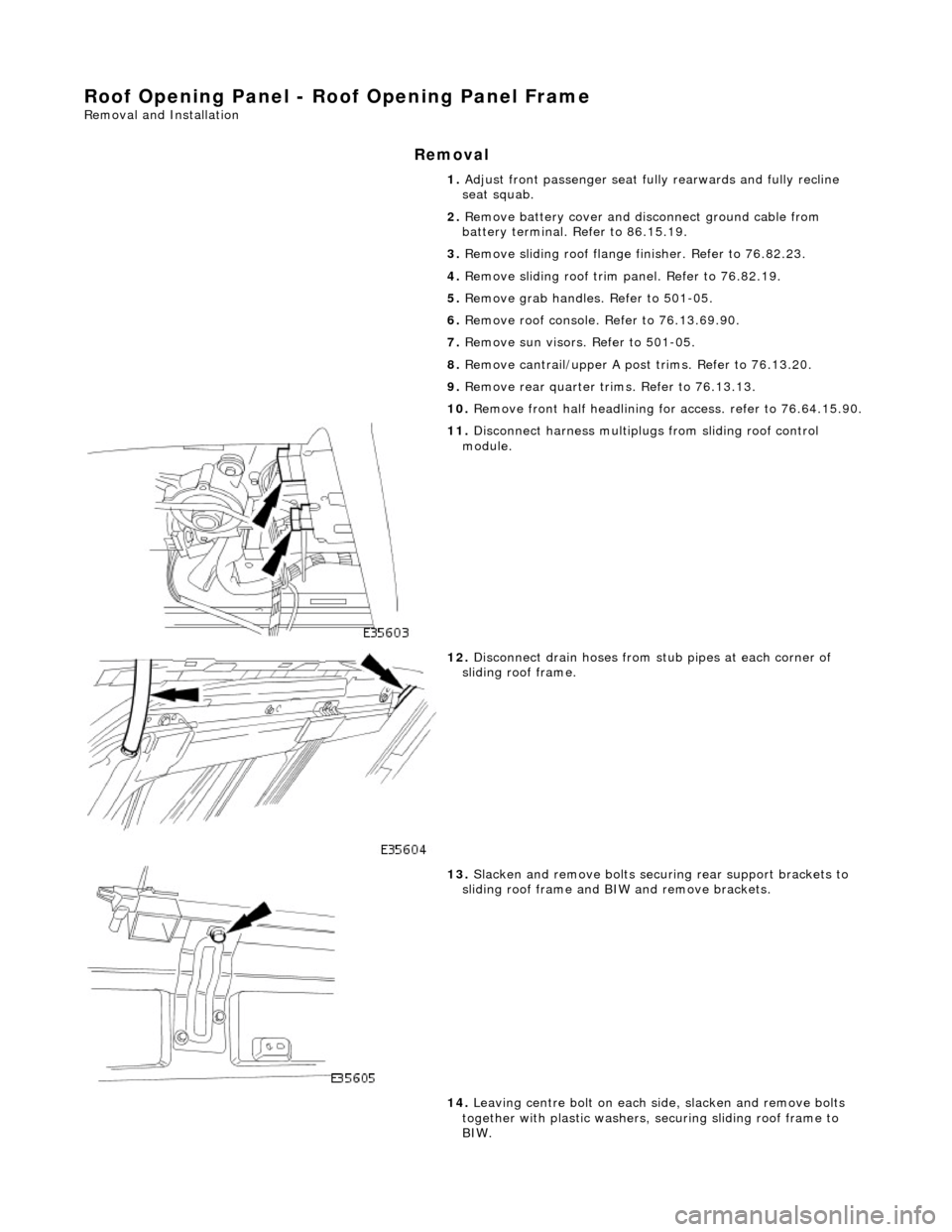
11. Disconnect harness multiplugs from sliding roof control
module.
12. Disconnect drain hoses from stub pipes at each corner of
sliding roof frame.
13. Slacken and remove bolts securi ng rear support brackets to
sliding roof frame and BIW and remove brackets.
14. Leaving centre bolt on each side, slacken and remove bolts
together with plastic washers, securing sliding roof frame to
BIW.
Page 2334 of 2490
tighten securing bolts.
7.
Align rear support brackets and tighten securing bolts.
8. Connect drain hoses to sliding roof frame stub pipes.
9. Fit headlining. Refer to 76.64.15.90.
10. Fit rear quarter trims. Refer to 76.13.13.
11. Fit cantrail/upper A post trims. Refer to 76.13.20.
12. Fit sun visors. Refer to 501-05.
13. Fit roof console. Refer to 76.13.69.90.
14. Fit grab handles. Refer to 501-05.
15. Fit sliding roof trim panel. Refer to 76.82.19.
16. Fit sliding roof flange fi nisher. Refer to 76.82.23.
17. Connect ground cable to batt ery terminal and fit battery
cover. Refer to 86.15.15.
18. Return front passen ger seat to original positions.
Page 2424 of 2490
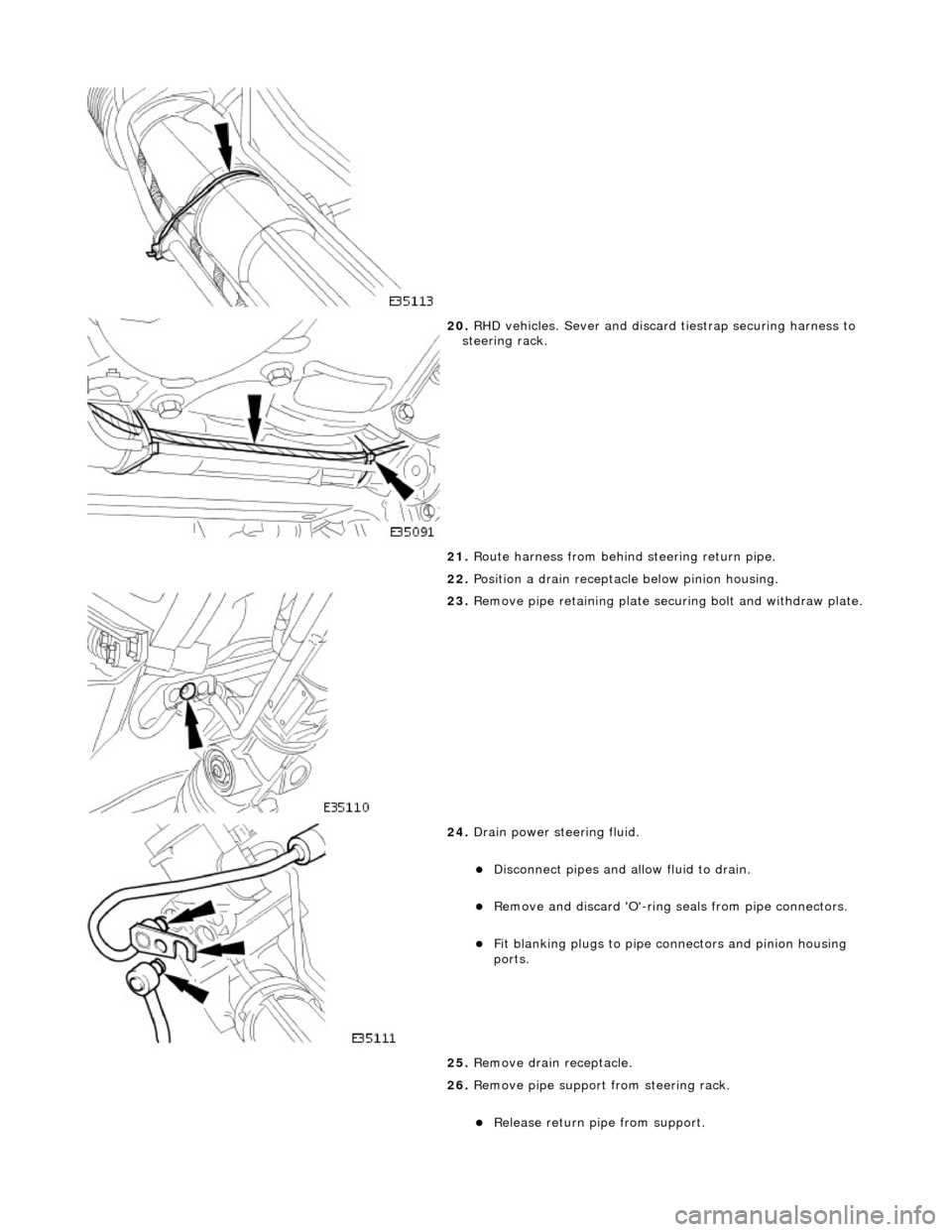
20. RHD vehicles. Sever and discard tiestrap securing harness to
steering rack.
21. Route harness from behind steering return pipe.
22. Position a drain receptacle below pinion housing.
23. Remove pipe retaining plate secu ring bolt and withdraw plate.
24. Drain power steering fluid.
Disconnect pipes and al low fluid to drain.
Remove and discard 'O'-ring seals from pipe connectors.
Fit blanking plugs to pipe connectors and pinion housing
ports.
25. Remove drain receptacle.
26. Remove pipe support from steering rack.
Release return pipe from support.
Page 2464 of 2490
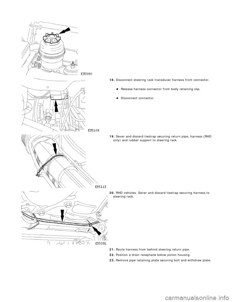
18. Disconnect steering rack transducer harness front connector.
Release harness connector from body retaining clip.
Disconnect connector.
19. Sever and discard tiestrap secu ring return pipe, harness (RHD only) and rubber support to steering rack.
20. RHD vehicles. Sever and discard tiestrap securing harness to
steering rack.
21. Route harness from behind steering return pipe.
22. Position a drain receptacle below pinion housing.
23. Remove pipe retaining plate secu ring bolt and withdraw plate.
Page 2465 of 2490
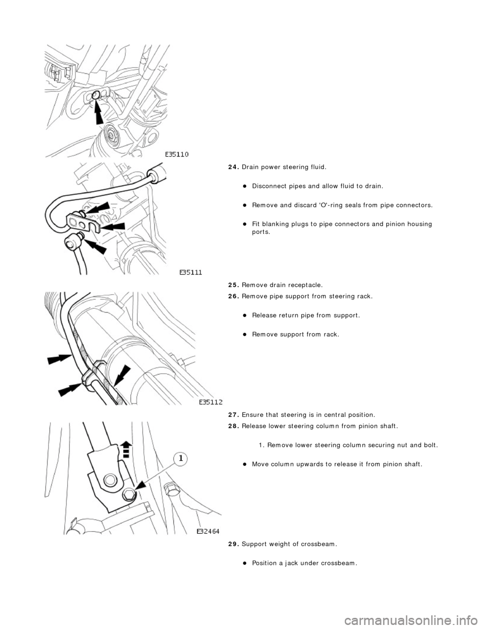
24. Drain power steering fluid.
Disconnect pipes and al low fluid to drain.
Remove and discard 'O'-ring seals from pipe connectors.
Fit blanking plugs to pipe connectors and pinion housing
ports.
25. Remove drain receptacle.
26. Remove pipe support from steering rack.
Release return pipe from support.
Remove support from rack.
27. Ensure that steering is in central position.
28. Release lower steering column from pinion shaft.
1. Remove lower steering co lumn securing nut and bolt.
Move column upwards to release it from pinion shaft.
29. Support weight of crossbeam.
Position a jack under crossbeam.