Page 1260 of 2490

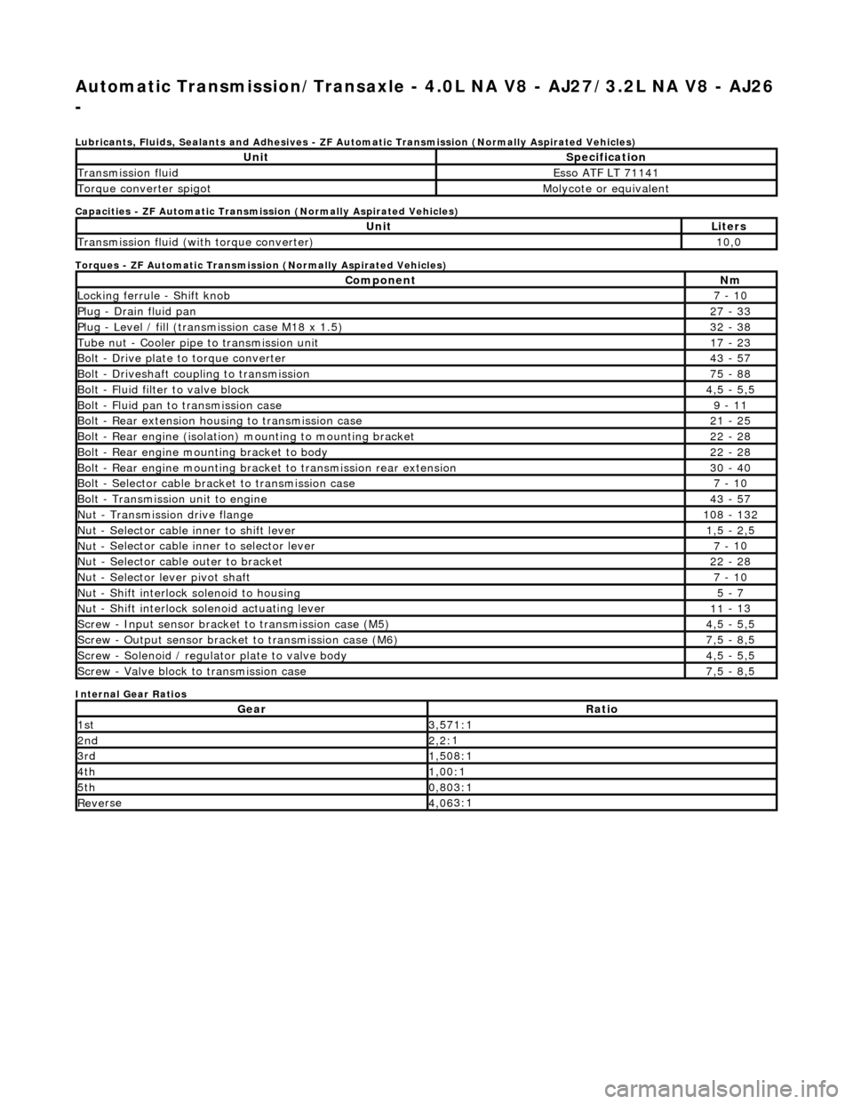
Automatic Transmission/Transaxle - 4.0L NA V8 - AJ27/3.2L NA V8 - AJ26
-
Lubri c
ants, Fluids, Sealants and Adhesives - ZF Au
tomatic Transmission (Normally Aspirated Vehicles)
Capacities - ZF Automatic Transmission (Normally Aspirated Vehicles)
Torques - ZF Automatic Transmission (Normally Aspirated Vehicles)
Internal Gear Ratios
UnitS p
ecification
Transmissi
on fluidEsso
ATF LT 71141
Torque converter spigotMolyc
o
te or equivalent
UnitLi
t
ers
Transmissi
on fluid (with
torque converter)
10
,0
Com p
onent
Nm
Locki
n
g ferrule - Shift knob
7 -
10
P
l
ug - Drain fluid pan
27
-
33
P
l
ug - Level / fill (transmission case M18 x 1.5)
32
-
38
Tu
be
nut - Cooler pipe to transmission unit
17
-
23
B
o
lt - Drive plate to torque converter
43
-
57
B
o
lt - Driveshaft coupling to transmission
75
-
88
Bo
lt
- Fluid filter to valve block
4,
5 -
5,5
Bolt
-
Fluid pan to transmission case
9 -
11
B
o
lt - Rear extension housing to transmission case
21
-
25
Bolt
-
Rear engine (isolation) mounting to mounting bracket
22
-
28
Bolt -
Rear engine moun
ting bracket to body
22
-
28
Bolt
-
Rear engine mounting bracke
t to transmission rear extension
30 -
40
B
o
lt - Selector cable bracket to transmission case
7 -
10
Bolt
-
Transmission unit to engine
43
-
57
Nu
t -
Transmission drive flange
1
08 -
132
Nu
t -
Selector cable inner to shift lever
1,
5 -
2,5
Nu
t -
Selector cable inner to selector lever
7 -
10
Nu
t -
Selector cable outer to bracket
22
-
28
Nu
t
- Selector lever pivot shaft
7 -
10
Nu
t -
Shift interlock solenoid to housing
5 -
7
Nut -
Shift interlock solenoid actuating lever
11
-
13
Sc
re
w - Input sensor bracket to transmission case (M5)
4,
5 -
5,5
Screw
-
Output sensor bracket to transmission case (M6)
7,
5 -
8,5
Screw
-
Solenoid / regulator plate to valve body
4,
5 -
5,5
Sc
re
w - Valve block to transmission case
7,
5 -
8,5
GearRatio
1s
t3,57
1:1
2n
d2,2:
1
3r
d1,50
8:1
4t
h1,00
:1
5t
h0,80
3:1
Re
ve
rse
4,
06
3:1
Page 1378 of 2490
21. Detach the rotary switch.
1. Remove the switch fixings.
2. Displace the switch harness from the clips.
22. Disconnect the fluid cooler pipes.
Unscrew the cooler pipe tube nu ts, one at each side of the
transmission casing.
Discard the 'O' rings.
Plug the pipes an d transmission.
23. Remove the three bolts which se cure the torque converter to
the drive plate.
1. Remove the access cover.
2. Rotate the crankshaft and hold to prevent movement, and remove the bolts.
24. Remove the LH and RH cataly st mounting brackets from the
transmission case.
Remove the bolts.
Page 1383 of 2490
Automatic Transmission/Transaxle - 4.0L NA V8 - AJ27/3.2L NA V8 - AJ26
- Transmission
Installation
Installation
Special Tool(s)
Engine support
303-021
Engine lifting brackets
303-536
1. Clean all mating faces and relevant parts.
2. Apply lubricant, Molycote or equivalent, to the spigot of the
torque converter.
3. Align the engine drive plate.
1. Rotate the crankshaft to position the ORANGE dot
within the indicated sector.
• NOTE: Viewed from the rear of the vehicle.
2. Keeping the dot within the sector, align the nearest converter fixing hole to the access aperture.
4. Align the torque converter
1. Rotate the converter to position the BLUE dot within the indicated sector.
2. Keeping the dot within the sector, align the nearest fixing boss as indicated, so that when the two units
are mated, the converter need only be moved the
minimum amount.
Page 1385 of 2490
not be trapped when the mounting is fitted.
9. Remove the transmission jack.
10. Fit the three bolts which secure the torque converter to the
drive plate.
1. Loosely assemble all three drive plate to torque converter bolts. Whilst preventing crankshaft
rotation, tighten the three converter bolts to the
specified torque figure.
2. Fit the blanking plug.
11. Connect the transmission harness multiplug.
1. Engage the multiplug.
2. Rotate the locking lever to secure.
12. Connect the selector cable to the selector lever and fit the
abutment bracket to the transmission casing. Tighten the nut
and two bolts to the specified torque figure.
Page 1388 of 2490

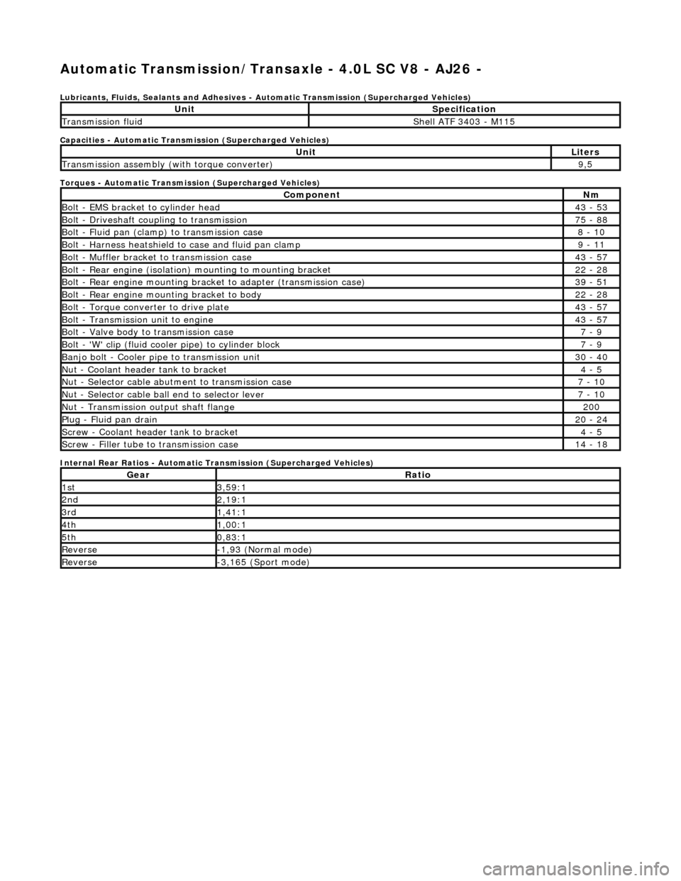
Automatic Transmission/Transaxle - 4.0L SC V8 - AJ26 -
Lubricants, Fluids, Sealants and Adhesives - Automatic Transmission (Supercharged Vehicles)
Capacities - Automatic Transmission (Supercharged Vehicles)
Torques - Automatic Transmission (Supercharged Vehicles)
Internal Rear Ratios - Automatic Transmission (Supercharged Vehicles)
UnitSpecification
Transmission fluidShell ATF 3403 - M115
UnitLiters
Transmission assembly (with torque converter)9,5
ComponentNm
Bolt - EMS bracket to cylinder head43 - 53
Bolt - Driveshaft coupling to transmission75 - 88
Bolt - Fluid pan (clamp) to transmission case8 - 10
Bolt - Harness heatshield to case and fluid pan clamp9 - 11
Bolt - Muffler bracket to transmission case43 - 57
Bolt - Rear engine (isolation) mounting to mounting bracket22 - 28
Bolt - Rear engine mounting brac ket to adapter (transmission case)39 - 51
Bolt - Rear engine mounting bracket to body22 - 28
Bolt - Torque converter to drive plate43 - 57
Bolt - Transmission unit to engine43 - 57
Bolt - Valve body to transmission case7 - 9
Bolt - 'W' clip (fluid cooler pipe) to cylinder block7 - 9
Banjo bolt - Cooler pipe to transmission unit30 - 40
Nut - Coolant header tank to bracket4 - 5
Nut - Selector cable abutment to transmission case7 - 10
Nut - Selector cable ball end to selector lever7 - 10
Nut - Transmission output shaft flange200
Plug - Fluid pan drain20 - 24
Screw - Coolant header tank to bracket4 - 5
Screw - Filler tube to transmission case14 - 18
GearRatio
1st3,59:1
2nd2,19:1
3rd1,41:1
4th1,00:1
5th0,83:1
Reverse-1,93 (Normal mode)
Reverse-3,165 (Sport mode)
Page 1390 of 2490

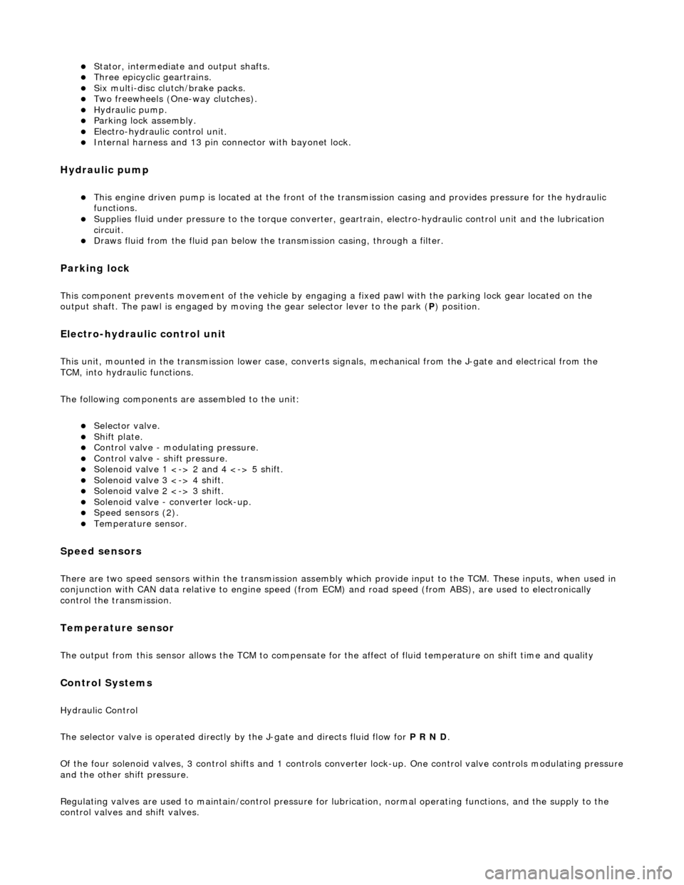
Stator, intermediate and output shafts. Three epicyclic geartrains. Six multi-disc clutch/brake packs. Two freewheels (One-way clutches). Hydraulic pump. Parking lock assembly. Electro-hydraulic control unit. Internal harness and 13 pin connector with bayonet lock.
Hydraulic pump
This engine driven pump is located at the front of the transmission casing and provides pressure for the hydraulic
functions.
Supplies fluid under pressure to the torq ue converter, geartrain, electro-hydraulic control unit and the lubrication
circuit.
Draws fluid from the fluid pa n below the transmission casing, through a filter.
Parking lock
This component prevents movement of th e vehicle by engaging a fixed pawl with the parking lock gear located on the
output shaft. The pawl is engaged by movi ng the gear selector lever to the park (P) position.
Electro-hydraulic control unit
This unit, mounted in the transmission lower case, converts signals, mechanical from the J-gate and electrical from the
TCM, into hydraulic functions.
The following components ar e assembled to the unit:
Selector valve. Shift plate. Control valve - modulating pressure. Control valve - shift pressure. Solenoid valve 1 <-> 2 and 4 <-> 5 shift. Solenoid valve 3 <-> 4 shift. Solenoid valve 2 <-> 3 shift. Solenoid valve - converter lock-up. Speed sensors (2). Temperature sensor.
Speed sensors
There are two speed sensors within the transmission assembly which provide input to the TCM. These inputs, when used in
conjunction with CAN data relative to engine speed (from ECM) and road speed (from ABS), are used to electronically
control the transmission.
Temperature sensor
The output from this sensor allows the TCM to compensate for the affect of fluid temperature on shift time and quality
Control Systems
Hydraulic Control
The selector valve is operated directly by the J-gate and directs fluid flow for P R N D.
Of the four solenoid valves, 3 control shifts and 1 controls converter lock-up. One control valve controls modulating pressure
and the other shift pressure.
Regulating valves are used to maintain/control pressure for lu brication, normal operating functions, and the supply to the
control valves and shift valves.
Page 1452 of 2490
Discard the Dowty seals.
Fit blanking plugs to the pipe and transmission.
24. Disconnect the fluid cooler lower pipe.
Remove the 'banjo' bolt.
Discard the Dowty seals.
Fit blanking plugs to the pipe and transmission.
25. Remove the three bolts which se cure the torque converter to
the drive plate.
1. Remove the access cover.
2. Rotate the crankshaft for access to each bolt and hold
to prevent movement. Remove each bolt.
26. Remove the LH and RH cataly st mounting brackets from the
transmission case.
Remove the two bolts from each side.
27. On the RH side, clear the cooler pipe for access.
28. NOTE: Viewed from the rear of the vehicle.
Remove the two upper bolts, as indicated, transmission to
engine.
Page 1459 of 2490
6. Fit the mounting bracket for th e front muffler. Tighten the two
bolts to the specified torque figure.
7. Secure the transmission to the engine.
Loosely assemble - Cooler pipe clip bolt.
Loosely assemble - Ground lead bolt.
Loosely assemble - Starter cable clips, two bolts.
Loosely assemble - Catalyst bracket bolts, two each side.
Loosely assemble - Rema ining eight bolts.
Refer to the illustration - tighten in sequence 1,2,3,4 then
in any order.
8. Secure the torque converter to the engine.
1. Fit, but do not tighten, the three bolts which secure the torque converter to the drive plate.
Prevent crankshaft rotation and tighten ALL converter
bolts to the specified torque figure.
2. Fit the blanking plug to the cylinder block access aperture.
9. Secure the oil cooler pipes.
Fit new Dowty washers to each union. Connect the upper
and lower cooler pipes.
Tighten to the specified torque figure.