Page 826 of 2490
6. Rotate the crankshaft until the triangular arrow indent on
the drive plate is visible thro ugh the access hole; confirm
that the timing flat on ea ch camshaft is uppermost.
7. Install the crankshaft setting peg 303-531 to the crankshaft
position sensor location.
1. Install the crankshaft setting peg 303-531.
Position the crankshaft so that the setting peg engages
fully into the timing slot.
2. Install and tighten the bolt to secure the setting peg.
8. Lower the vehicle on the ramp.
9. Install the camshaft locking tool 303-530 to Bank 1 camshafts,
aligning the shafts sl ightly as necessary.
10. CAUTION: Use a length of steel strip that will not fall
into the timing cover.
Protect the upper face of the ti ming cover from scratches, when
Page 880 of 2490

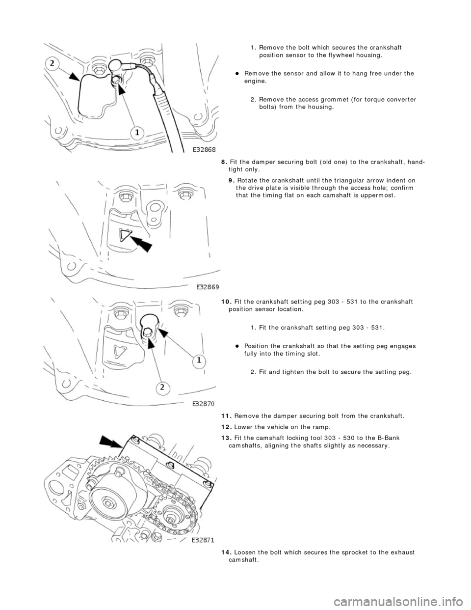
1. Remove the bolt which secures the crankshaft position sensor to the flywheel housing.
Remove the sensor and allow it to hang free under the
engine.
2. Remove the access grommet (for torque converter bolts) from the housing.
8. Fit the damper securing bolt (old one) to the crankshaft, hand-
tight only.
9. Rotate the crankshaft until the triangular arrow indent on
the drive plate is visible thro ugh the access hole; confirm
that the timing flat on ea ch camshaft is uppermost.
10. Fit the crankshaft setting peg 303 - 531 to the crankshaft
position sensor location.
1. Fit the crankshaft setting peg 303 - 531.
Position the crankshaft so that the setting peg engages
fully into the timing slot.
2. Fit and tighten the bolt to secure the setting peg.
11. Remove the damper securing bolt from the crankshaft.
12. Lower the vehicle on the ramp.
13. Fit the camshaft locking tool 303 - 530 to the B-Bank
camshafts, aligning the shafts slightly as necessary.
14. Loosen the bolt which secures the sprocket to the exhaust
camshaft.
Page 886 of 2490

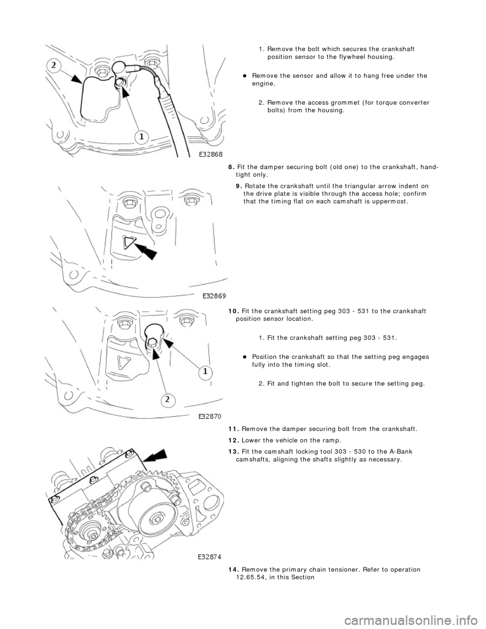
1. Remove the bolt which secures the crankshaft position sensor to the flywheel housing.
Remove the sensor and allow it to hang free under the
engine.
2. Remove the access grommet (for torque converter bolts) from the housing.
8. Fit the damper securing bolt (old one) to the crankshaft, hand-
tight only.
9. Rotate the crankshaft until the triangular arrow indent on
the drive plate is visible thro ugh the access hole; confirm
that the timing flat on ea ch camshaft is uppermost.
10. Fit the crankshaft setting peg 303 - 531 to the crankshaft
position sensor location.
1. Fit the crankshaft setting peg 303 - 531.
Position the crankshaft so that the setting peg engages
fully into the timing slot.
2. Fit and tighten the bolt to secure the setting peg.
11. Remove the damper securing bolt from the crankshaft.
12. Lower the vehicle on the ramp.
13. Fit the camshaft locking tool 303 - 530 to the A-Bank
camshafts, aligning the shafts slightly as necessary.
14. Remove the primary chain tens ioner. Refer to operation
12.65.54, in this Section
Page 905 of 2490
Remove the bolts which secure the downpipe to the lower
mounting bracket.
Remove the downpipe assembly.
Repeat the above operations for the other downpipe
catalytic converter.
47. Remove the two bolts which secure each mounting bracket to
the bell housing and remove the brackets.
48. Disconnect the driveshaft (propshaft) flange from the
transmission output flange.
Remove the three bolts which secure the flange. Rotate
the shaft for access to each bolt.
Disconnect the shaft and reposition it to the side.
49. Remove the securing bolt and disconnect the ground lead
from the transmission casing.
50. Disconnect the oil cooler pi pes (where fitted) from the
engine.
1. Remove the bolt which secures the pipe clamping
plate. Remove the clamping plate.
2. Place a drain tray beneat h the pipes and disconnect
Page 1063 of 2490
Th
e starter drive plate is attached to the rear of the crankshaft by eight bolts.
Timing Disc
A timing disc, for the engine speed sensor, is spot-w elded to the front face of the starter drive plate.
Starter Drive Plate
Page 1106 of 2490
Intake Air Distribution and Filtering -
Torque Specificat
ions
Comp
onent
Nm
Thr
o
ttle intake elbow to intake manifold
18
-
24
Thro
tt
le body to throttle intake elbow
18
-
24
Left-hand support
bracket to
th
rottle intake elbow
16
-
20
Right-hand support
bracket to
throttle intake elbow
16
-
20
B
l
anking plate to throttle intake elbow
18
-
24
Inta
k
e manifold to engine
20
-
22
Supe
rcharger
drive belt idler pulley bolt
34
-
46
Supercharger
drive belt te
nsioner to alternator mounting bracket bolt
39
-
51
Supercharger
to eng
ine bolts
18
-
24
Charge air cooler in
let assembly to charge ai
r cooler bolts
18
-
24
Supercharger
outlet duct to supercharger bolts9-1
1
Charge air cooler in
let assembly to superchar
ger ou
tlet duct bolts
18-
24
Charge air cool
er to charge
air cooler adaptor
11
-
13
B
y
-pass valve to throttle intake elbow
8-
1
2
Page 1115 of 2490

is at
tached to the three mounting bosses between the V of the cylinder block
has a fil
led for life inte
rnal lubrication system
is po
sitively aligned with the drive
belt by a doweled mounting bracket
C
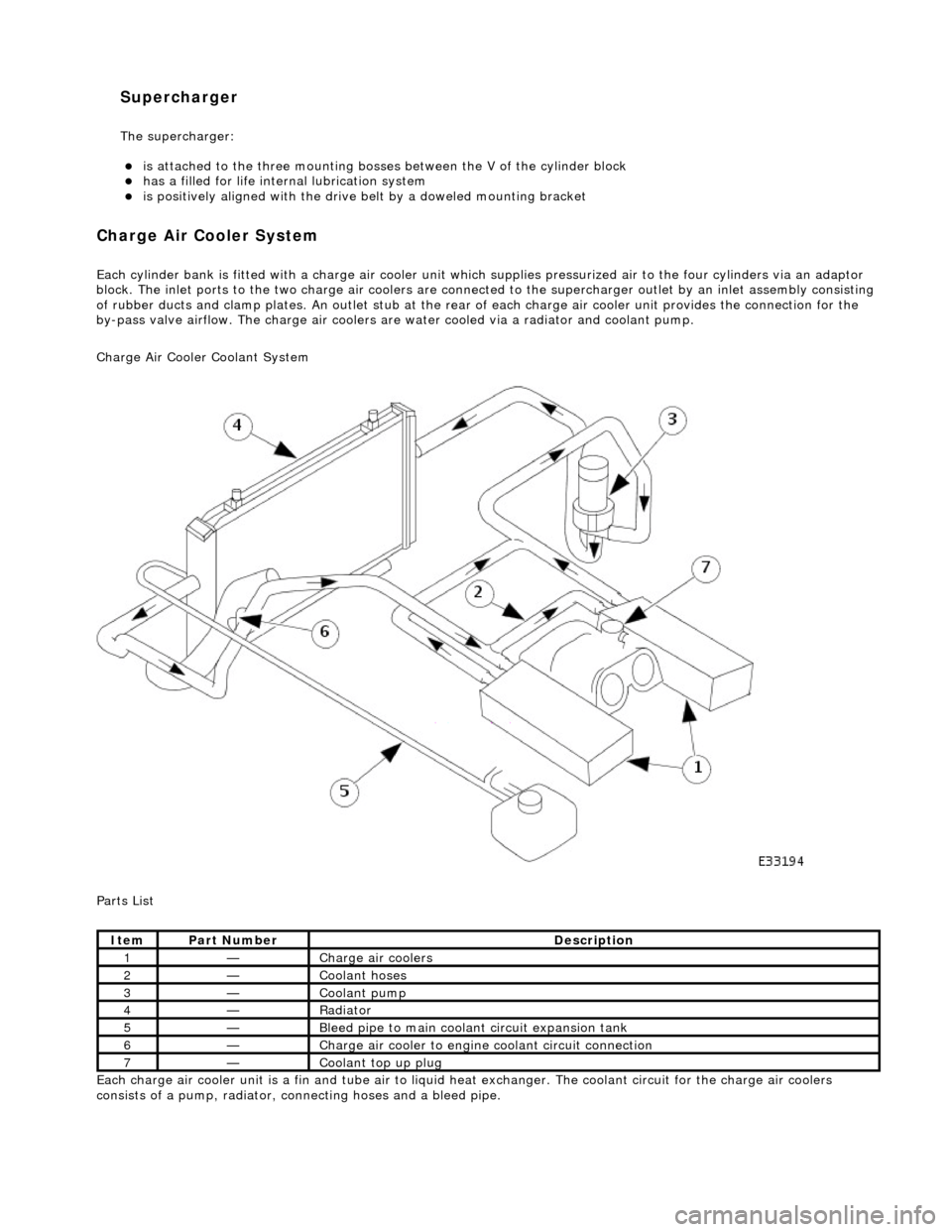
harge Air Cooler System
Each cyl
inder bank is fitted with a charge air cooler unit wh
ich supplies pressurized air to the four cylinders via an adaptor
block. The inlet ports to the tw o charge air coolers are connected to the supercharger outlet by an inle t assembly consisting
of rubber ducts and clamp plates . An outlet stub at the rear of each charge air cooler unit provides the connection for the
by-pass valve airflow. The charge air coolers ar e water cooled via a radiator and coolant pump.
Charge Air Cooler Coolant System
Parts List
Each charge air cooler unit is a fin and tube air to liquid heat exchanger. The coolant circuit for the charge air coolers
consists of a pump, ra diator, connecting hoses and a bleed pipe.
It
em
Par
t Number
De
scription
1—Charge air cool
ers
2—Coo
lant hoses
3—Coo
lant pump
4—Radi
ator
5—Ble
ed pipe to main coolant circuit expansion tank
6—Charge air cooler to en
gine
coolant circuit connection
7—Coo
lant top up plug
Supercharger
The supe
rcharger:
Page 1178 of 2490
Throttle Position (TP) Sensor
Location
P
arts List
sen
d
s the ECM a signal indica
ting throttle plate angle
is
the main input to the ECM from the driver
i
s
a dual Hall effect devi
ce mounted on the motor en d of the throttle body
Two additional sensors are attached to the throttle body to provide additional feedback to the ECM: a mechanical guard
position sensor and an accelerator pedal position sensor.
Cam s
haft Position (CMP) Sensor
sen
d
s the ECM a signal indicating camshaft po
sition for fuel synchronization purposes
is
a variable reluctance device mounted on bank 2 cylinder side face
generates a signal when the ri
ng
fitted to the bank 2 inlet
camshaft passes the sensor
Cranksha
ft Position (CKP) Sensor
i
s
a variable reluctance device
mounted on the engine oil pan
Ite
m
Par
t
Number
De
scr
iption
1—Acce
le
rator pedal and mechanic
al guard position sensors
2—Throttle
(blade)
position sensor