Page 629 of 2490

• N
OTE: Remove the sensor and allow it to hang free under the engine.
1
. Remove the bolt which secures the crankshaft position sensor to
the flywheel housing.
2. Remove the access grommet (for torque converter bolts) from the housing.
14. Install the damper securing bolt (old one) to the crankshaft, hand-tight
only.
15
.
Rotate the crankshaft until the triangular arrow indent on the drive plate is
visible through the access hole; confirm that the timing flat on each
camshaft is uppermost.
16
.
Install the crankshaft setting peg 3 03 - 531 to the crankshaft position
sensor location.
1. Install the crankshaft setting peg 303 - 531.
Position
the crankshaft so that the setting peg engages fully into the
timing slot.
2. Install and tighten the bolt to secure the setting peg.
17. Remove the damper securing bolt from the crankshaft.
18. Lower the vehicle on the ramp.
19
.
Install the camshaft locking tool 303 - 530 to the A-Bank camshafts,
aligning the shafts slightly as necessary.
20
.
Loosen the bolt which secures the sprocket to the camshaft.
Page 638 of 2490

se
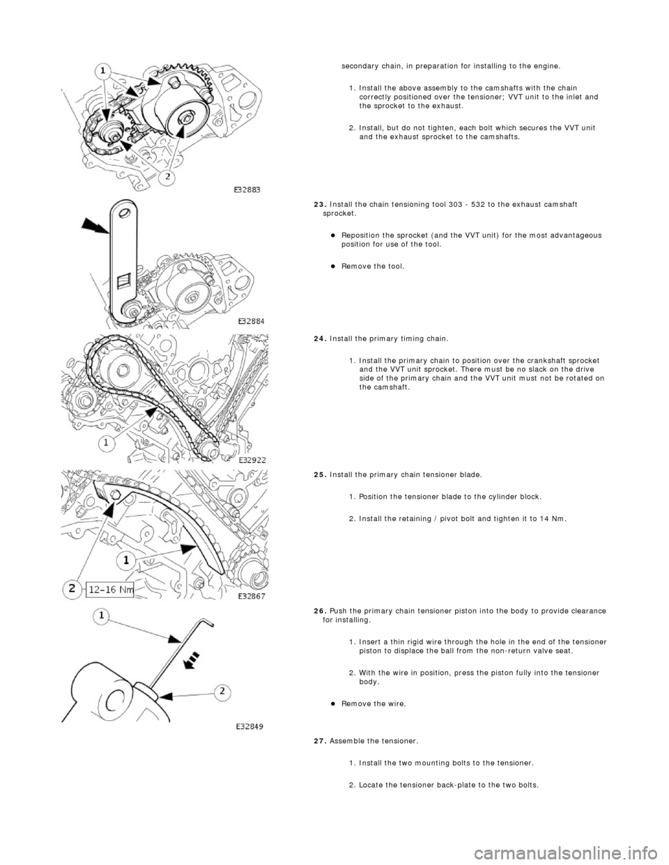
condary chain, in preparation for installing to the engine.
1. Install the above assembly to the camshafts with the chain correctly positioned over the tensioner; VVT unit to the inlet and
the sprocket to the exhaust.
2. Install, but do not tighten, each bolt which secures the VVT unit and the exhaust sprocket to the camshafts.
23 .
Install the chain t
ensioning tool 303 - 532 to the exhaust camshaft
sprocket.
Re p
osition the sprocket (and the VVT unit) for the most advantageous
position for use of the tool.
Re
move the tool.
24 . Install the
primary timing chain.
1. Install the primary chain to position over the crankshaft sprocket and the VVT unit sprocket. There mu st be no slack on the drive
side of the primary chain and the VVT unit must not be rotated on
the camshaft.
25 . Install the pri
mary chain tensioner blade.
1. Position the tensioner blade to the cylinder block.
2. Install the retaining / pivot bolt and tighten it to 14 Nm.
26 . P
ush the primary chain tensioner piston into the body to provide clearance
for installing.
1. Insert a thin rigid wire through the hole in the end of the tensioner
piston to displace the ball from the non-return valve seat.
2. With the wire in position, press the piston fully into the tensioner body.
Rem
ove the wire.
27. Assemble the tensioner.
1. Install the two mounting bolts to the tensioner.
2. Locate the tensioner back-plate to the two bolts.
Page 665 of 2490

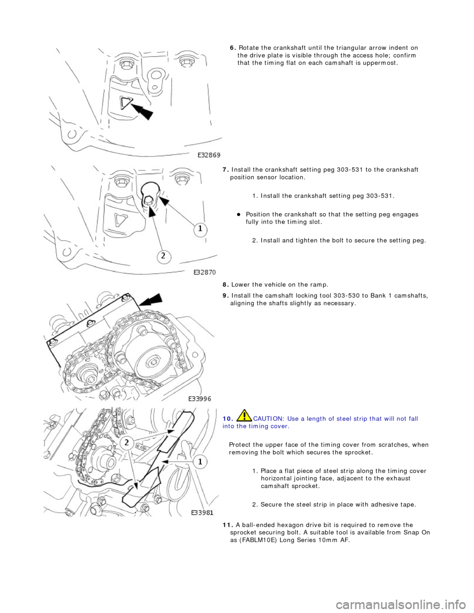
6. Rotate the crankshaft until the triangular arrow indent on
the drive plate is visible thro ugh the access hole; confirm
that the timing flat on ea ch camshaft is uppermost.
7. Install the crankshaft setting peg 303-531 to the crankshaft
position sensor location.
1. Install the crankshaft setting peg 303-531.
Position the crankshaft so that the setting peg engages
fully into the timing slot.
2. Install and tighten the bolt to secure the setting peg.
8. Lower the vehicle on the ramp.
9. Install the camshaft locking tool 303-530 to Bank 2 camshafts,
aligning the shafts sl ightly as necessary.
10. CAUTION: Use a length of steel strip that will not fall
into the timing cover.
Protect the upper face of the ti ming cover from scratches, when
removing the bolt which secures the sprocket.
1. Place a flat piece of stee l strip along the timing cover
horizontal jointing face, adjacent to the exhaust
camshaft sprocket.
2. Secure the steel strip in place with adhesive tape.
11. A ball-ended hexagon drive bit is required to remove the
sprocket securing bolt. A suitable tool is available from Snap On as (FABLM10E) Long Series 10mm AF.
Page 669 of 2490
6. Rotate the crankshaft until the triangular arrow indent on
the drive plate is visible thro ugh the access hole; confirm
that the timing flat on ea ch camshaft is uppermost.
7. Install the crankshaft setting peg 303-531 to the crankshaft
position sensor location.
1. Install the crankshaft setting peg 303-531.
Position the crankshaft so that the setting peg engages
fully into the timing slot.
2. Install and tighten the bolt to secure the setting peg.
8. Lower the vehicle on the ramp.
9. Install the camshaft locking tool 303-530 to Bank 2 camshafts,
aligning the shafts sl ightly as necessary.
10. CAUTION: Use a length of steel strip that will not fall
into the timing cover.
Protect the upper face of the ti ming cover from scratches, when
Page 673 of 2490

6. Rotate the crankshaft until the triangular arrow indent on
the drive plate is visible thro ugh the access hole; confirm
that the timing flat on ea ch camshaft is uppermost.
7. Install the crankshaft setting peg 303-531 to the crankshaft
position sensor location.
1. Install the crankshaft setting peg 303-531.
Position the crankshaft so that the setting peg engages
fully into the timing slot.
2. Install and tighten the bolt to secure the setting peg.
8. Lower the vehicle on the ramp.
9. Install the camshaft locking tool 303-530 to Bank 1 camshafts,
aligning the shafts sl ightly as necessary.
10. CAUTION: Use a length of steel strip that will not fall
into the timing cover.
Protect the upper face of the ti ming cover from scratches, when
removing the bolt which secures the sprocket.
1. Place a flat piece of stee l strip along the timing cover
horizontal jointing face, adjacent to the exhaust
camshaft sprocket.
2. Secure the steel strip in place with adhesive tape.
11. A ball-ended hexagon drive bit is required to remove the
sprocket securing bolt. A suitable tool is available from Snap On as (FABLM10E) Long Series 10mm AF.
Page 678 of 2490
6. Rotate the crankshaft until the triangular arrow indent on
the drive plate is visible thro ugh the access hole; confirm
that the timing flat on ea ch camshaft is uppermost.
7. Install the crankshaft setting peg 303-531 to the crankshaft
position sensor location.
1. Install the crankshaft setting peg 303-531.
Position the crankshaft so that the setting peg engages
fully into the timing slot.
2. Install and tighten the bolt to secure the setting peg.
8. Lower the vehicle on the ramp.
9. Install the camshaft locking tool 303-530 to Bank 1 camshafts,
aligning the shafts sl ightly as necessary.
10. CAUTION: Use a length of steel strip that will not fall
into the timing cover.
Protect the upper face of the ti ming cover from scratches, when
Page 696 of 2490

Engine - Flexplate4.0L NA V8 - AJ27/3.2L NA V8 - AJ26
In-vehicle Repair
Removal
Installation
1. Open the engine compartment and fit paint protection sheets.
2. Disconnect the batt ery ground cable.
Remove the battery cover.
3. Remove the Engine Covers, Air Intake Tube, Catalytic
Converters and the Front Muffler. Drain the transmission fluid
and remove the transmission for access.
Refer to Operation 44.20. 01 Transmission Remove, in
Section 307-01A, which includes each of the above
operations.
4. Remove the drive plate.
Prevent the drive plate from rotating by use of a small
wedge in the ring gear.
Remove the bolts which secure the drive plate to the
crankshaft.
Remove the drive plate.
5. Clean the crankshaft mating face and any other components
which are to be refitted.
1. Fit the drive plate.
Fit and align the drive plate to the crankshaft.
Fit, but not tighten, the bolt s which secure the drive plate
to the crankshaft.
Prevent the drive plate from rotating by use of a small
wedge in the ring gear.
2. Tighten the securing bolts in two stages and in the order
shown.
Page 698 of 2490

Engine - Flexplate4.0L SC V8 - AJ26
In-vehicle Repair
Removal
Installation
1. Open the engine compartment and fit paint protection sheets.
2. Disconnect the batt ery ground cable.
Remove the battery cover.
3. Remove the Engine Covers, Air Intake Tube, Catalytic
Converters and the Front Muffler. Drain the transmission fluid
and remove the transmission for access.
Refer to Operation 44.20. 01 Transmission Remove, in
Section 307-01B, which includes each of the above
operations.
4. Remove the drive plate.
Prevent the drive plate from rotating by use of a small
wedge in the ring gear.
Remove the bolts which secure the drive plate to the
crankshaft.
Remove the drive plate.
5. Clean the crankshaft mating face and any other components
which are to be refitted.
1. Fit the drive plate.
Fit and align the drive plate to the crankshaft.
Fit, but not tighten, the bolt s which secure the drive plate
to the crankshaft.
Prevent the drive plate from rotating by use of a small
wedge in the ring gear.
2. Tighten the securing bolts in two stages and in the order
shown.