Page 463 of 2490

No
ise
S
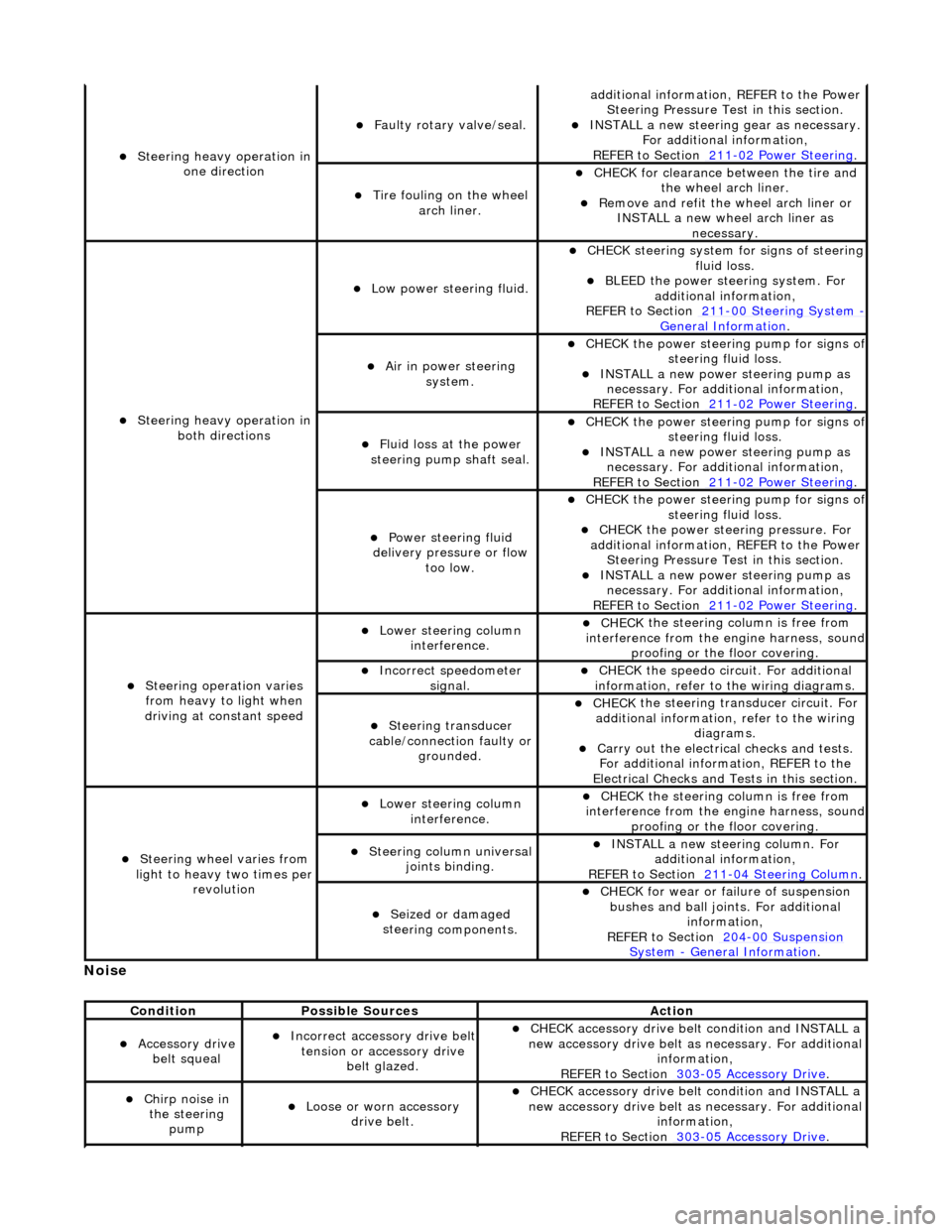
teering heavy operation in
one direction
F
aulty rotary valve/seal.
addi
tional information, REFER to the Power
Steering Pressure Test in this section.
INST
ALL a new steering
gear as necessary.
For additional information,
REFER to Section 211
-0
2 Power Steering
.
Ti
re fouling on the wheel
arch liner.
CHECK for
clearance be
tween the tire and
the wheel arch liner.
R
emove and refit the wheel arch liner or
INSTALL a new wheel arch liner as necessary.
S
teering heavy operation in
both directions
Low power steer
ing fluid.
CHE
CK steering system
for signs of steering
fluid loss.
BLEE
D the power steering system. For
additional information,
REFER to Section 211
-0
0 Steering System
- General Informati
on
.
Ai
r in power steering
system.
CHECK
the power steering pump for signs o
f steering fl
uid loss.
INST
ALL a new power steering pump as
necessary. For additi onal information,
REFER to Section 211
-0
2 Power Steering
.
Fluid loss at the power
steering pump shaft seal.
CHECK
the power steering pump for signs o
f steering fl
uid loss.
INST
ALL a new power steering pump as
necessary. For additi onal information,
REFER to Section 211
-0
2 Power Steering
.
Power steeri
ng fluid
delivery pressure or flow too low.
CHECK
the power steering pump for signs o
f steering fl
uid loss.
CHECK
the power stee
ring pressure. For
additional information, REFER to the Power Steering Pressure Test in this section.
INST
ALL a new power steering pump as
necessary. For additi onal information,
REFER to Section 211
-0
2 Power Steering
.
Steeri
ng operation varies
from heavy to light when
driving at constant speed
Lower steeri
ng column
interference.
CHECK
the steering co
lumn is free from
interference from the en gine harness, sound
proofing or the floor covering.
Incorre
ct sp
eedometer
signal.
CHECK
the speedo circ
uit. For additional
information, refer to the wiring diagrams.
Steeri
ng transducer
cable/connection faulty or grounded.
CHECK
the steering transducer circuit. For
additional information, refer to the wiring diagrams.
Carry ou
t the electrical checks and tests.
For additional information, REFER to the
Electrical Checks and Tests in this section.
Steeri
ng wheel varies from
light to heavy two times per revolution
Lower steeri
ng column
interference.
CHECK
the steering co
lumn is free from
interference from the en gine harness, sound
proofing or the floor covering.
Steeri
ng column universal
joints binding.
IN
STALL a new steering column. For
additional information,
REFER to Section 211
-0
4 Steering Column
.
Seized or damaged
ste
ering components.
CHECK
for wear or failure of suspension
bushes and ball join ts. For additional
information,
REFER to Section 204
-00
Suspension
Sy
stem
- General
Information
.
Cond
ition
Possib
le Sources
Acti
on
Acce
ssory drive
belt squeal
Incorre
ct accessory drive belt
tension or accessory drive belt glazed.
CHECK
accessory drive belt condition and INSTALL a
new accessory drive belt as necessary. For additional
information,
REFER to Section 303
-0
5 Accessory Drive
.
Chir
p noise in
the steering pump
Loose or worn accessory dr
ive belt.
CHECK
accessory drive belt condition and INSTALL a
new accessory drive belt as necessary. For additional
information,
REFER to Section 303
-0
5 Accessory Drive
.
Page 473 of 2490
6. NO
TE: The suitable funnel should have the a capacity of 4
litres and O-ring seal
• NOTE: The suitable funnel must be tightly sealed to the
power steering fluid reservoi r to avoid fluid leakage.
Install a suitable funnel onto the power steering fluid
reservoir.
7. WARNING: Do not work on or under a vehicle supported
only by a jack. Always support the vehicle on safety stands.
Raise and support the vehicle with the wheels just clear of the
ground.
8. CAUTI
ONS:
Steps 8 and 9 must be carried out within 2 - 3 seconds of
each other. Failure to follow this instruction may result in damage
to the power steering system.
Be prepared to collect escaping fluids.
Using the suitable funnel, top up the power steering system
with the specified fluid. Make su re the fluid level is maintained
at two thirds full in the funnel.
9. CAUTI
ONS:
Be prepared to collect escaping fluids.
Page 489 of 2490

modul
e. This regulates the fluid flow
through the hydraulic control valve, wh ich determines the amount of steering
assistance.
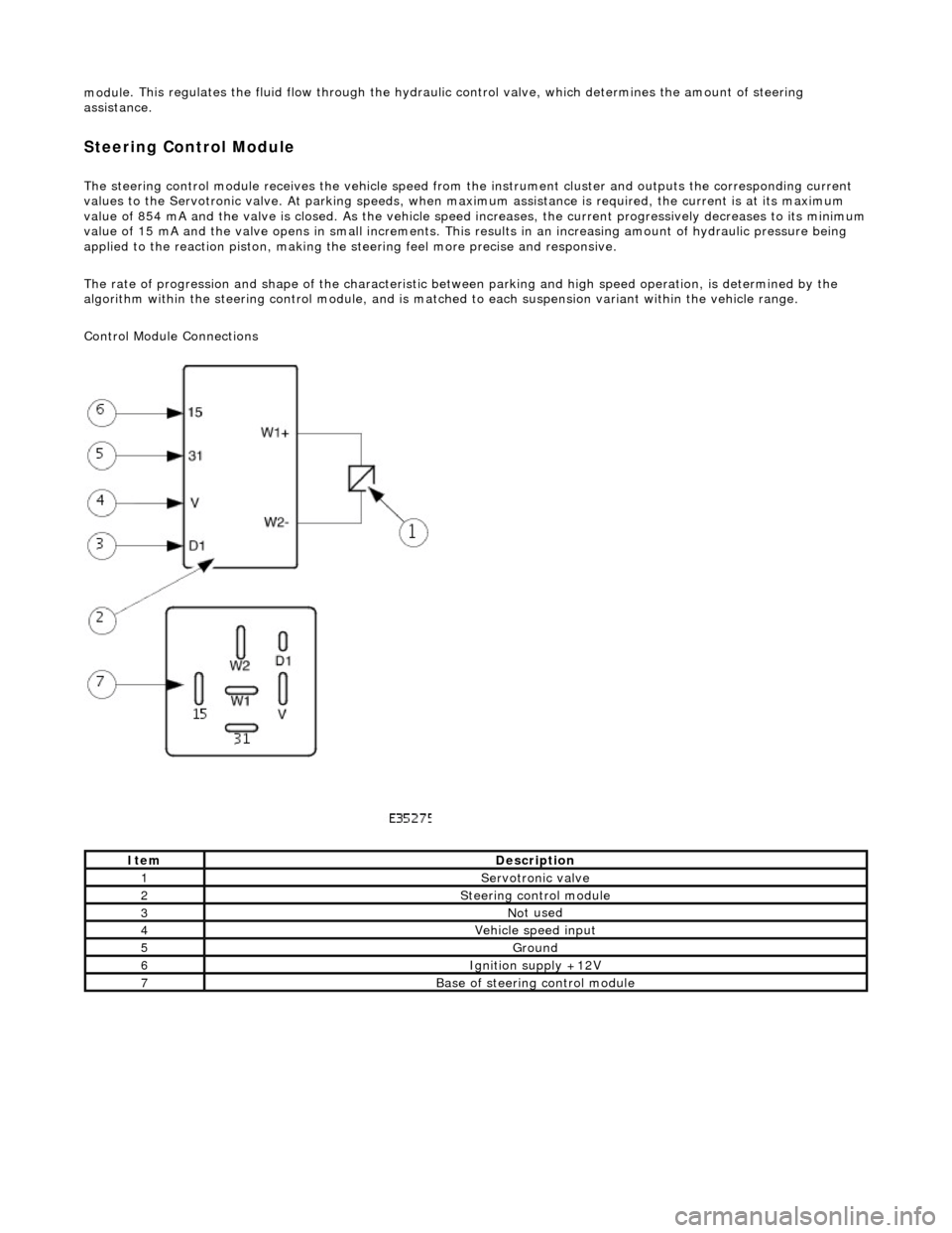
Steering Control Module
The steering control
module re
ceives the vehicle speed from the instrument cluster and outputs the corresponding current
values to the Servot ronic valve. At parking speeds, wh en maximum assistance is required , the current is at its maximum
value of 854 mA and the valve is closed. As the vehicle speed increases, the current progressively decreases to its minimum
value of 15 mA and the valve opens in sma ll increments. This results in an increasing amount of hydraulic pressure being
applied to the reaction piston, making the steering feel more precise and responsive.
The rate of progression and shape of the characteristic between parking and high speed operation, is determined by the
algorithm within the steering control module, and is matched to each suspension variant within the vehicle range.
Control Module Connections
It
em
De
scription
1Servotronic valve
2Steeri
ng control module
3No
t used
4Vehi
cle speed input
5Ground
6Ignition su
pply +12V
7Base of
steering control module
Page 519 of 2490
Steering Column Switches - Steering Colu
mn Multifunction Switch
Re
moval and Installation
Remov
al
Installation
1.
D
isconnect battery ground cable; refer to 86.15.19.
2. NOTE: Steering wheel must be in the straight ahead position.
Remove steering wheel.
3. Di
splace cancellation module connector from mounting bracket
and disconnect.
4. Di
splace flasher/headlamp/t
rip switch connectors from
mounting bracket and disconnect.
Cut an
d remove appropriate harness securing ties.
5. Re
move switchgear.
1. Remove two screws which secure switch assembly/cancellation module to mounting bracket.
2. Displace switchgear from mounting bracket.
3. Route switchgear harness through mounting bracket and remove switchgear.
1. Installation is reverse of removal.
Page 534 of 2490
Wi
th EM015 and PI031 (PI032) disconnected, measure
the resistance between EM015/009 (EM015/008) and
PI031/001 (PI032/001)
1
Is
the resistance < 0.5 OHM?
Yes GO to A5
No Inspect harness / connec tors EM015, PI031 (PI032),
PI001/016 (PI001/027) for corrosion, damage, bent or
pushed back pins and repair as required. Test the system
for normal operation.
A5: CHEC K HA
RNESS (GROUND) CONTINUITY
Page 535 of 2490
Pin
point test B: P1393 (P1398) VVT solenoid circuit high input
W
ith EM014 disconnected, measure the resistance
between EM014/009 and ground EM016L
1
I
s the resistance < 0.5 OHM?
Yes Reconnect EM014, EM015, PI031 or (PI032)
GO to A6
No Inspect harness / connector EM014, ground stud and
splice EMS37 for corrosion, damage, bent or pushed back
pins and repair as required. Test the system for normal
operation.
A6
: END
Perform
appropriate service drive cycle and check for the
presence of DTC.
1
Has
the fault code cleared?
Yes STOP
No Contact Jaguar Service
P
INPOINT TEST B : P1393 (P1398) VVT SOLENOID CIRCUIT HIGH INPUT
•
NOTE: References in brac
kets are for Bank B (2)
T
EST CONDITIONS
D
ETAILS/RESULTS/ACTIONS
B1
: RETRIEVE DTCS
•
NOTE: Battery and or ECM disconnection prior to scanning wi
ll erase all data, ensure that the correct DTC is present.
Page 538 of 2490
Measure
the voltage between PI031/002 (PI032/002) and
ground EM016L
1
B+ ?
Yes
GO to B5
No
Inspect EM020/010, PI001, PI031 (PI032) for bent /
pushed back pins or locate and repair harness / splice
PIS06.
B5
: CHECK HARNESS SHORT TO GROUND
Page 539 of 2490
W
ith EM015 and EM014 disconnected, measure the
insulation resistance between EM015/009 (EM015/008)
and ground EM014/009
1
I
s the resistance > 10 MOHM?
Yes Do not reconnect
GO to B6
No Inspect EM015, and EM014 for corrosion, bent / pushed
back pins or locate and repa ir the harness / connector.
Test the system for normal operation.
B6
: CHECK HARNESS SHORT CORE TO CORE