Page 50 of 2490
Date of
Manufacture
T
h
e date of manufacture (Build Date) of a vehicle is define
d as the calendar month and year in which the bodyshell and
powertrain are combined and the completed vehicle leaves the production line. For certain markets, VIN labels carry the
month and year of manufacture. For other markets, the vehicle Build Date is also displayed on a metal plate located at the
top of the battery tray in the trunk.
ANTI-T
HEFT LABELS
F
or
some markets, anti-theft labels bearing the VIN printed on
a special anti-forgery background are positioned on certain
body components. An additional anti-theft label is positioned on the LH side of the engine/automatic transmission casing.
Anti-theft labels must not be removed from a vehicle unless necessitated by component renewal.
ItemDe scrip
tion
1Gross Vehic
l
e Weight
2Gross Trai
n W
eight
3Maxim
u
m Permitted Front Axle Loading
4Maxim
u
m Permitted Rear Axle Loading
Page 56 of 2490
Jacking and Lifting - Using the Vehicle Jack
Gene
ral Procedures
1.
WARN
INGS:
ENSURE THAT THE VEHICLE IS STANDING ON FIRM, LEVEL
GROUND.
DO NOT START OR RUN THE ENGINE WHILE THE VEHICLE
IS ONLY SUPPORTED BY THE VEHICLE JACK.
Position the jack at the appropri ate front or rear jacking point.
Put the parkin
g brake ON and
the transmission in Park.
Chock the wh
eels to prevent movement of the vehicle.
2.
Locat e
the arm of the jack securely in the jacking socket.
R
e
move the rubber cover from the socket.
3. Raise/lower the vehicle using the jack ratchet handle.
4. Remove the jack from the jacking point.
Fi
t the rubber cover to the jacking socket.
Page 265 of 2490

W
heels and Tires - Wheels and Tires
D
iagnosis and Testing
General Not
es
1.
1. Factory in
stalled tires and wheels are designed to provide optimum ride and ha
ndling characteristics when inflated
to the recommended inflation pressures, with vehicle loads not exceeding the full-rated load capacity.
2. 2. Correct tire pressures and driv ing technique have an important influence on tire life. Heavy cornering, excessively
rapid acceleration and unnecessary sharp braking increase tire wear.
3. 3. Replacement tires should follow the recommended:
Size
.
Speed
rating.
Load range. Radial c
onstruction type.
4. 4. The use of any other size or type of wheel / tire may seriously affect:
Safety. Ri
de.
Handlin
g.
Speed
ometer / odometer calibration.
Vehi
cle ground clearance.
Ti
re clearance between
body and chassis.
Wh
eel bearing life.
Brake cooli
ng.
5. 5. Wheels must be renewed when:
Impact damaged. Heavil
y corroded.
Porous W
heel stud holes or se
ats become damaged.
They h
ave excessive radial or lateral runout.
Safety Notes
• WAR
NINGS:
DO NOT MIX DIFFERENT TYPES OF TIRES ON THE SAM E VEHICLE, HANDLING MAY BE SERIOUSLY AFFECTED
RESULTING IN LOSS OF CONTROL.
DO NOT MIX DIFFERENT TYPES OF TIRES ON THE SAM E VEHICLE, HANDLING MAY BE SERIOUSLY AFFECTED
RESULTING IN LOSS OF CONTROL.
A TIRE AND WHEEL MUST ALWAYS BE CORRECTLY MATCHED. WIDER OR NARROWER TIRES THAN RECOMMENDED
COULD CAUSE DANGER THROUGH SUDDEN DEFLATION.
WHEN USING THE TEMPORARY SPARE WHEEL, SPEED MUST NOT EXCEED 80 KM/H (50 MPH). DRIVE WITH CAUTION
AND REPLACE WITH THE SPECIFIED WHEEL / TIRE ASSEMBLY AS SOON AS POSSIBLE.
TRACTION CONTROL (IF AVAILABLE) MUST NOT BE ENGAGED WITH THE TEMPORARY SPARE WHEEL FITTED.
Page 266 of 2490

WHE
N CHANGING A WHEEL, ENSURE THAT THE VEHICLE CANNOT MOVE. ALWAYS APPLY THE PARK BRAKE AND
SELECT TRANSMISSION 'P' POSITION.
NEVER RUN THE ENGINE WITH ONE WHEEL OFF THE GROUND, FOR EXAMPLE, WHEN CHANGING THE WHEEL. THE
VEHICLE COULD MOVE.
TIGHTEN THE WHEEL NUTS TO SPECIFICATION. WHEELS MAY COME LOOSE IF OVER OR UNDER TIGHTENED.
USE WHEELS AND WHEEL NUTS DESI GNED FOR XJ SERIES VEHICLES ONLY. AFTERMARKET WHEELS OR WHEEL
NUTS MAY NOT FIT OR FUNCTION PROPERLY AND COULD CAUSE INJURY OR DAMAGE.
In
spection and Verification
To maximize ti
re performance, inspec
t the tires frequently for signs of:
Unev
en wear.
Incorrect
ti
re pressure.
Wh
ee
l imbalance.
Cuts. Abrasi
ons.
B
u
lges (blister).
Ply s
e
paration.
Embedded objects. Impact damage.
Inspe c
tion should be
more frequent when:
Continuo
us high speed op
eration is required.
Ra
pid or extreme temperatures changes occur.
R
o
ad surfaces are rough.
Roads ar
e littered
with debris.
Tread W
e
ar Indicator
•
NO
TE: Tire condition must comply with prevailing local legislation.
New tires must be installed if the wear in dicators are exposed or if there is severe shoulder wear. Shoulder wear is usually
caused by either excessive camber or toe on tires.
T i
re Vibration Diagnosis
A
tir
e vibration diagnostic procedure always
begins with a road test. The road test and the custom er interview (if available)
will provide much of the information need ed to find the source of vibration.
During the road test, drive the vehicle on a road that is smooth and free of undulations. If vibration is apparent, note and
record the following:
The s p
eed at which the vibration occurs.
W
h
at type of vibration occurs in each
speed range - mechanical or audible.
How the vibrati
on is affected
by changes in the following:
- -engine torque
- -vehicle speed
- -engine speed.
Type of v i
bration - sensitivity:
- - torque sensitive,
- - vehicle speed sensitive,
- - or engine speed sensitive.
Page 275 of 2490
R
equire no adjustment and are non-serviceable items.
Accelerometers
The three accelerometers:
Sense veh
icle body movement.
Gen
erate an analogue voltag
e (maximum +5 volts) proportional to body movement.
Pr
ovide inputs to the adapti
ve damping control module.
The two vertical acce lerometers are mounted on the bulkhead and in the trunk.
The lateral accelerometer is mounted in the ECM housing.
Ada
ptive Damping Control Module (ADCM)
The ADCM
:
Is
mounted on the fascia support bracket.
Controls the four adaptiv
e dampers in re
sponse to analogue and digital inputs.
It
em
De
scription
1Battery su
pply
2Ignition su
pply
3Ground
4Input from verti
cal accelerometer, front
5Input from verti
cal accelerometer, rear
6Input from later
al accelerometer
7F
ootbrake operation signal
8Vehi
cle speed input
9D
amper control signals
10Ou
tput to message center
11D
iagnostic connector serial link
Page 276 of 2490

Is hard-wi
red to the instrume
nt cluster message center.
Is hard
-wired to the J1962 diagnostic connector.
Op
era
tion
Th
e
system selects the soft or
firm damper setting according to the current ro ad and driving conditions, to optimise vehicle
ride and handling.
With the vehicle stationary, the dampers are in the firm setting, but will normally switch to the soft setting when the vehicle
exceeds 8 km/h (5 mile/h); all dampers are switched simultaneously.
Sudden movement of the vehicle body, in response to road inputs, is detected by the vertical accelerometers, and the ADCM
switches the dampers to the firm setting to give improved damping of the resultant oscillations.
When cornering forces are detected by th e lateral accelerometer, the ADCM switches the dampers to the firm setting to
reduce the roll rate an d improve wheel control.
After the event has passed, the dampers revert to the soft setting.
When the footbrake is applied, the ADCM re ceives a signal and calculates the rate of vehicle deceleration. If the deceleration
rate is greater than a certain threshold, the dampers are switched to the firm setting to reduce the pitch rate and improve
wheel control.
If a system failure occurs, the ADCM grounds the output line to the instrument cluster message center, which displays a
text warning SUSPENSION FAULT and illuminates the amber warning lamp. Under fault conditions the system always fails to
the firm setting, so that the vehicle will be safe to drive un der all road and driving conditions.
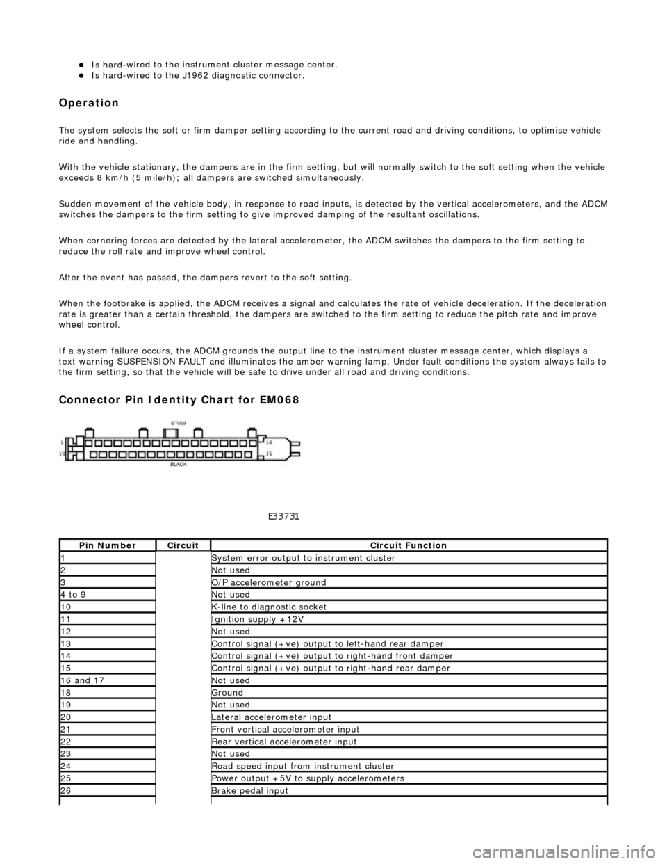
Connector Pin Identity Chart for EM068
Pin
Number
Ci
rcui
t
Circuit Functi
on
1System erro
r output to instrument
cluster
2Not
used
3O/
P a
ccelerometer ground
4 to
9
Not
used
10K-
li
ne to diagnostic socket
11Ignition su
pply +12V
12Not
used
13Control signal (+ve) output
to l
eft-hand rear damper
14Control signal (+ve) output
to right-hand front damp
er
15Control signal (+ve) output
to right-hand rear
damper
16
a
nd 17
No
t
used
18Ground
19No
t
used
20Lateral
accelerometer i
nput
21Front vertical ac
celerometer in
put
22Rear vertical
acce
lerometer input
23No
t
used
24R
o
ad speed input from
instrument cluster
25Power output +5V to suppl y accelerometers
26Brake peda
l input
Page 282 of 2490

Driveshaft - Driveshaft
Remo
val and Installation
Remov
a
l
CAUTI
O
N: To preserve 'drive line' refine
ment, individual parts, other than fixings, MUST NOT be renewed. In the event
of any balance or driveshaft component related problem, the complete assembly must be renewed. Under no circumstances
may the flexible (Jurid) coupling be remo ved from the driveshaft (or its fixings be loosened). Do not drop or subject the
driveshaft to damage.
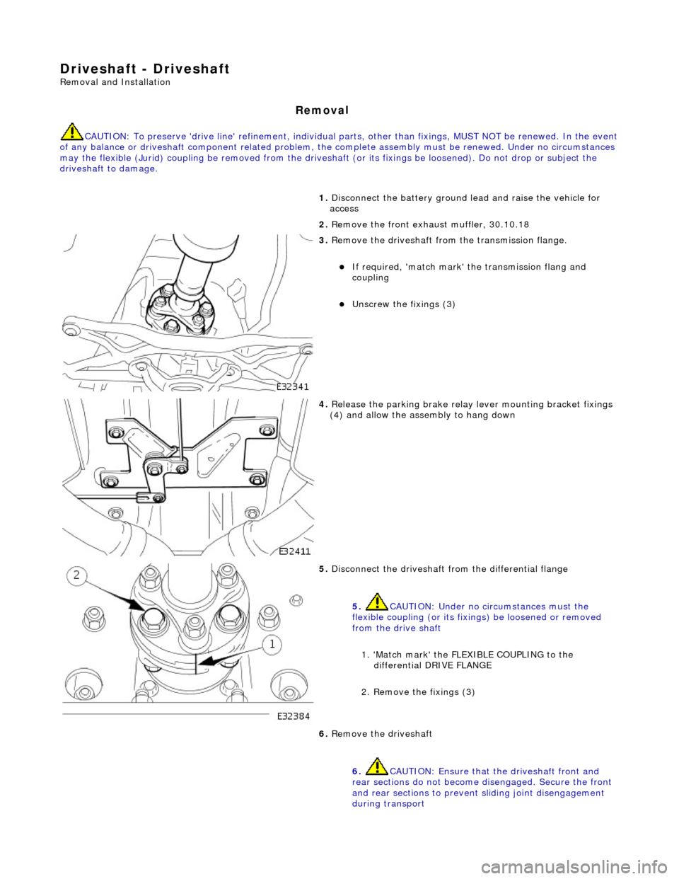
1. Disc
onnect the battery ground
lead and raise the vehicle for
access
2. Remove the front exha ust muffler, 30.10.18
3. Re
move the driveshaft from
the transmission flange.
If required, 'match mark'
the transmissi on flang and
coupling
Unscrew the fi xings (3)
4. Relea s
e the parking brake relay
lever mounting bracket fixings
(4) and allow the assembly to hang down
5. Disc onne
ct the driveshaft fr
om the differential flange
5. CAUTION: Under no circumstances must the
flexible coupling (or its fixings) be loosened or removed
from the drive shaft
1. 'Match mark' the FLEX IBLE COUPLING to the
differential DRIVE FLANGE
2. Remove the fixings (3)
6. Re
move the driveshaft
6. CAUTION: Ensure that the driveshaft front and
rear sections do not become disengaged. Secure the front
and rear sections to preven t sliding joint disengagement
during transport
Page 287 of 2490
R
ear Drive Axle/Differential - Differ
ential Output Shaft End Float Check
Gen
eral Procedures
1.
Di
sconnect the battery ground lead
2. Raise the vehicle for access
3. Mo
unt a dial test indicator (DTI
) to the differential housing with
the probe resting on the axle sh aft flange (the DTI probe must
be parallel to the output shaf t center line and NOT the axle
shaft)
4. Chec
k the end float
Pus
h the wheel / shaft assembly INWARDS
Zero the DTI
P
ull the wheel / shaft assembly OUTWARDS
N
ote the reading
5. Check the specification
0 t
o 0,15 mm GOOD
0,
15 mm + NOT GOOD; Renew the output shaft bearing