Page 981 of 2490
1.
Disconnect and reposition the union nut, upper cooler
pipe to radiator. Di sconnect the pipe.
2. Remove and discard the O- ring seal from the pipe
and fit blanking plugs to the pipe and to the union on
the radiator.
10
.
Disconnect the radiator bottom hose.
1. Slacken the hose retaining clip and reposition the clip
along the hose.
2. Disconnect the hose from the radiator.
11
.
Disconnect the radiator top hose.
1. Slacken the hose retaining clip and reposition the clip
along the hose.
2. Disconnect the hose from the radiator.
12
.
Release the radiator top retaining panel.
R
emove the ten bolts which secure the panel.
13. Disconnect the discharge hose from the condenser.
1. Remove the bolt which secures the condenser discharge hose and disconnect the hose.
2. Remove and discard the O-ring seal from the hose.
Page 982 of 2490
3.
Fit blanking plugs to the
hose and to the condenser.
14 . Di
sconnect the condenser jump
hose from the receiver /
drier.
1. Remove the bolt which secures the condenser jump hose and discon nect the hose.
2. Remove and discard the O-ring seal from the hose.
3. Fit blanking plugs to the hose and to the receiver / drier.
15 . Remove the
radiator top retaining panel.
1. Remove the panel.
2. Remove the radiator top mounting bushes.
16. Disconnect the bonnet switch harness.
17. R
emove the radiator.
Re
move the radiator assembly.
Cl
ean coolant spil
lage from the radiator lower carrier
panel.
18. Remove the condenser from the radiator.
1. Remove the two bolts which secure the condenser to the radiator.
2. Remove the condenser.
If necessary, remove the jump hose from the
condenser.
Page 985 of 2490
10
.
Fit the radiator top securing panel.
1. Position and align th e top securing panel.
2. Fit the eight securing bolts to the panel.
11
.
Tighten the ten bolts which secu re the radiator top panel.
12
.
Connect the radiator coolant bottom hose.
1. Reposition and connect the bottom hose to the radiator.
2. Reposition the hose clip.
13. Fit the twin fan and motor assembly. Refer to Operation
26.25.12 in this section.
14. Remove the temporary wooden support strut and reconnect
the gas struts to the engine compartment cover.
15. Check the level and replenish the transmission fluid as
necessary. Refer to Section 307 for the recommended
procedure.
Page 992 of 2490

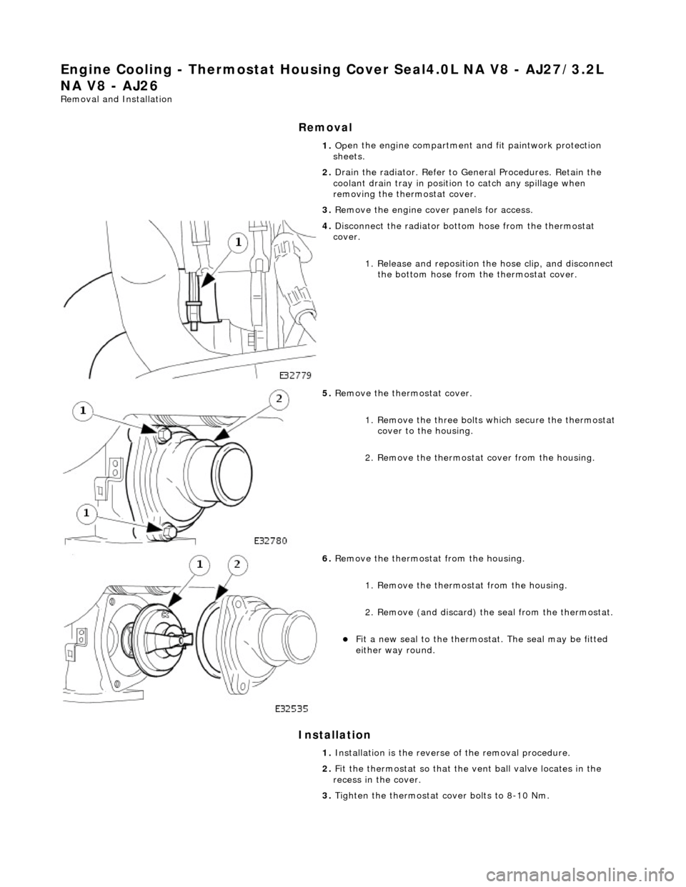
Engine Cooling - Thermostat4.0L NA V8 - AJ27/3.2L NA V8 - AJ26
Remo
val and Installation
Remov
a
l
Installation
1. Op
en the engine compartment and fit paintwork protection
sheets.
2. Drain the radiator. Refer to Ge neral Procedures. Retain the
coolant drain tray in position to catch any spillage when
removing the thermostat cover.
3. Remove the engine cove r panels for access.
4. Disc
onnect the radiator bott
om hose from the thermostat
cover.
1. Release and reposition th e hose clip, and disconnect
the bottom hose from th e thermostat cover.
5. Re
move the thermostat cover.
1. Remove the three bolts which secure the thermostat cover to the housing.
2. Remove the thermostat cover from the housing.
6. Re
move the thermostat from the housing.
1. Remove the thermostat from the housing.
2. Remove (and discard) th e seal from the thermostat.
Fit a new seal to the thermostat. Th
e seal may be fitted
either way round.
1. Installation is th e reverse of the re moval procedure.
2. Fit the thermostat so that the vent ball valve locates in the
recess in the cover.
3. Tighten the thermostat cover bolts to 8-10 Nm.
Page 995 of 2490

Engine Co
oling - Thermostat Housing
Cover4.0L NA V8 - AJ27/3.2L NA V8
- AJ26
Re
moval and Installation
Remov
al
Installation
1. O
pen the engine compartment and fit paintwork protection
sheets.
2. Drain the radiator. Refer to Ge neral Procedures. Retain the
coolant drain tray in position to catch any spillage when
removing the thermostat cover.
3. Remove the engine cove r panels for access.
4. Di
sconnect the radiator bott
om hose from the thermostat
cover.
1. Release and reposition th e hose clip, and disconnect
the bottom hose from th e thermostat cover.
5. R
emove the thermostat cover.
1. Remove the three bolts which secure the thermostat cover to the housing.
2. Remove the thermostat cover from the housing.
6. R
emove the thermostat from the housing.
1. Remove the thermostat from the housing.
2. Remove (and discard) th e seal from the thermostat.
Fit a new seal to the
thermost
at. The seal may be fitted
either way round.
1. Installation is th e reverse of the re moval procedure.
2. Fit the thermostat so that the vent ball valve locates in the
recess in the cover.
3. Tighten the thermostat cover bolts to 8-10 Nm.
Page 998 of 2490

Engine Cooli
ng - Thermostat Housing
Cover Seal4.0L NA V8 - AJ27/3.2L
NA V8 - AJ26
Re mo
val and Installation
Remova
l
Installation
1. Op
en the engine compartment and fit paintwork protection
sheets.
2. Drain the radiator. Refer to Ge neral Procedures. Retain the
coolant drain tray in position to catch any spillage when
removing the thermostat cover.
3. Remove the engine cove r panels for access.
4. Disc
onnect the radiator bott
om hose from the thermostat
cover.
1. Release and reposition th e hose clip, and disconnect
the bottom hose from th e thermostat cover.
5. Re
move the thermostat cover.
1. Remove the three bolts which secure the thermostat cover to the housing.
2. Remove the thermostat cover from the housing.
6. Re
move the thermostat from the housing.
1. Remove the thermostat from the housing.
2. Remove (and discard) th e seal from the thermostat.
Fit a new seal to the
thermostat. Th
e seal may be fitted
either way round.
1. Installation is th e reverse of the re moval procedure.
2. Fit the thermostat so that the vent ball valve locates in the
recess in the cover.
3. Tighten the thermostat cover bolts to 8-10 Nm.
Page 1269 of 2490

2.2. Check on non-volatile diagnostic memory by wr iting a test pattern and then reading it back.
3. 3. Internal 'watchdog' hardware to check whether the TCM has crashed.
Transmission Control Module Supply Voltage
The TCM monitors battery and igni tion switched supply voltages.
A permanent supply is used to maintain a battery backed 'memor y'. Should this supply be cut, due to battery disconnection
perhaps, the 'adaptive shift' valu es will be lost. This will result in a small reduction in shift quality for a period until th e
adaptions are 're-learned'
The TCM will adopt 'limp home' mode as a result of the supply voltage being >16V or <7V with an engine speed >1600
rpm.
Should the ignition supply be >7V but <9V the TCM will hold the gear that it has currently selected. If after 2.5 seconds,
with the engine speed >1600 rpm, the voltage remains at this level, 'limp home' mode will be adopted. The 2.5 second
delay is built in to prevent reaction to a momentary voltage fluctuation.
Operation
CAUTION: Disconnection of the TCM and / or the vehicle batt ery will cause system adaptions to be lost; this may be
apparent by shift quality degradation. Fo llowing reconnection, a period of 'varied' driving will reinstate adaptions and thus
normal operation. Please ensure that the customer is made aware that the adaption period is variable and may occur after
handover, as the transmission re-learns the prevailing driving style.
• NOTE: Should the TCM fail, please ensure that the control housing cooling fan is operating correctly. Failure of the cooling
fan MUST be rectified before renewing the TCM and details of a fan fa ilure should accompany the returned TCM.
The TCM processes information received in both analogue and digital form, such as:
Transmission input speed Transmission output speed Throttle position Pedal demand Gear selector position Engine torque Engine speed Transmission oil temperature Mode switch
This information is then used by the TC M to control shift energy management and decide which shift program to implement
and which gear to select.
The TCM uses the various sensors and inpu ts to monitor the correct operation of the system an d is programmed to take
default action and inform the operator when a fault occurs.
Safety Functions
The safety functions are designed to safeguard against inappr opriate actions by the operator as well as against system
malfunctions. The system prevents reve rse gear from being engaged at high forward speeds and prevents manual
downshifting at excessive engine speeds; these functions are not operational in mechanical limp-home mode.
The TCM constantly monitors the transmissi on for faults. In the event of a problem the TCM will adopt a 'limp home' mode
in which only P R N D - (selector in D but only fourth gear is enabled) are available. The operator will be made aware of
certain faults by an in strument panel warning.
The electrical and diagnostic system has been designed such that system integrity is protected at all times, the safety
concept being based on th e following three points:
Page 1357 of 2490
Automatic Transmission/Transaxle - 4.0L NA V8 - AJ27/3.2L NA V8 - AJ26
- Transmission Control Module (TCM)
In-vehicle Repair
Removal
1. Disconnect battery ground cable.
Remove the battery cover.
2. Remove the trim panel from the engine compartment,
passenger side.
1. Remove the left hand side enclosure panel.
2. If necessary, remove the centre trim panel.
3. Release the fixings and remove the cover from the ECM / TCM
housing.
4. Disconnect the TCM harness multiplug EM007.
5. Lift the TCM from its housing.