1998 JAGUAR X308 Pas pump
[x] Cancel search: Pas pumpPage 1784 of 2490
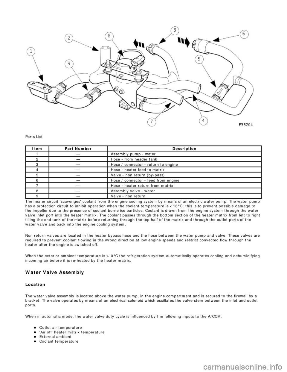
Parts List
The heater circuit 'scavenges' coolant from the engine cooling system by mean s of an electric water pump. The water pump
has a protection circuit to inhibit operation when the coolant temperature is <16°C; this is to prevent possible damage to
the impeller due to the presence of coolant borne ice particles. Coolant is drawn from the en gine system through the water
valve inlet port into the heater matrix. The coolant passes thro ugh the bottom section of the heater matrix from left to right
filling the end tank of the matrix before returning through the top half of the ma trix and through the outlet ports of the
water valve and back into the engine cooling system.
Non return valves are located in the heat er bypass hose and the hose between the water pump and valve. These valves are
required to prevent coolant flowing in th e wrong direction at low engine speeds and restrict convected flow through the
heater after the engine is switched off.
When the exterior ambient temperature is > 0°C the refrigerat ion system automatically operates cooling and dehumidifying
incoming air before it is re -heated by the heater matrix.
Water Valve Assembly
Location
The water valve assembly is located above the water pump, in the engine compartmen t and is secured to the firewall by a
bracket. The valve operates by means of an electrical solenoid which oscillates the valve stem between the inlet and outlet
ports.
When in automatic mode, the water valve duty cycle is influenced by the following inputs to the A/CCM:
Outlet air temperature 'Air off' heater matrix temperature External ambient Coolant temperature
ItemPart NumberDescription
1—Assembly pump - water
2—Hose - from header tank
3—Hose / connector - return to engine
4—Hose - heater feed to matrix
5—Valve - non return (by-pass)
6—Hose / connector - feed from engine
7—Hose - heater return from matrix
8—Assembly valve - water
9—Valve - non return
Page 1785 of 2490
Engine speed (valve closed with the engine not running) Demand (set) temperature In-car temperature sensor Solar sensor
Re-heating of the refrigerated air is contro lled by the time that the water valve is open (i.e. not energised) over a six secon d
interval. The duty cycle of the water valve, the time open / time closed, is controlled by the A/CCM.
Maximum heating demand will cause the water valve to be fu lly open (not energised) to allow maximum coolant flow
through the heater matrix.
At Maximum cooling, the water va lve will be fully closed (energised) to prevent hot (engine temperature) coolant entering
the heater circuit; the pump however will continue to circulate coolant through both the heater matrix and water valve
bypass.
The water valve defaults open when the ignition is OFF.
Under engine stall conditions, when ignition is ON, the water valve will be open.
Water Pump Assembly
Located in the same area as the water valve, the water pump continually circulates coolant through the heater matrix
except when the conditions below apply:
The engine coolant is below 16°C. The ignition is OFF. Under engine stall conditions, when ignition is ON. Control panel OFF
Non return valves
The heater bypass hose has a non-return valve, located between the engine feed and return hoses. The valve prevents the
water pump from recirculating coolant fro m the heater at low engine speeds.
The flow indicator arrow embossed on the valve bo dy MUST point towards the coolant header tank.
CAUTION: Coolant flow will be compromi sed if either valve is fitted incorrectly. Observe the correct direction.
A second non-return valve is located betw een the water pump and water valve. This valve prevents hot coolant from flowing
into the heater with the engine switched off. The flow indicator arrow MUST point towards the water pump.
Heater feed and return hoses
The heater feed and return hoses are connected to the engine feed and return hoses by 'Quick-Fit' connection unions. The
feed hose has a Norma R20 connector and the return hose a Norma push and seal connector. The coolant system bleed
joints have Cobra clamps. All remaining hose connections have spring band hose clamps.
The engine feed hose is connected to the engine bypass hous ing and the engine return hose is connected to the engine
water pump.
Clamp Identification
Page 1799 of 2490
Twin blower assemblies Center mounted evaporator, heater and air distribution unit Electric solenoid water valve controlled heating Electric water pump assembly Servo motor driven air distribution flaps Dedicated side glass defrost / demist vents External temperature sensor Motorised in-car aspirator Solar sensor
Electronic Control Panel
Liquid Crystal Display (LCD) Digital temperature display Manual fan speed level External temperature display Celsius / Fahrenheit selection Heated windshield switch (where fitted) Heated backlight switch Defrost switch Manual airflow distribution overrides (4) Access to self diagnostic system and error codes
Sensors
External ambient temperature sensor Motorized in-car aspirator Heater matrix temperature sensor Evaporator temperature sensor Solar sensor
These sensors feedback information to the Air Conditioning Control Module (A/CCM) which automatically adjusts air
temperature, airflow volume and distributi on from the air conditioning unit to maintain a stable passenger compartment
average temperature under changing weather conditions.
Major Components
Page 1833 of 2490
Control Components - Control Components
Diagnosis and Testing
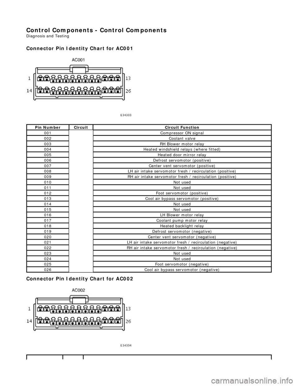
Connector Pin Identity Chart for AC001
Connector Pin Identity Chart for AC002
Pin NumberCircuitCircuit Function
001Compressor ON signal
002Coolant valve
003RH Blower motor relay
004Heated windshield relays (where fitted)
005Heated door mirror relay
006Defrost servomotor (positive)
007Center vent servomotor (positive)
008LH air intake servomotor fre sh / recirculation (positive)
009RH air intake servomotor fresh / recirculation (positive)
010Not used
011Not used
012Foot servomotor (positive)
013Cool air bypass servomotor (positive)
014Not used
015Not used
016LH Blower motor relay
017Coolant pump motor relay
018Heated backlight relay
019Defrost servomotor (negative)
020Center vent servomotor (negative)
021LH air intake servomotor fresh / recirculation (negative)
022RH air intake servomotor fresh / recirculation (negative)
023Not used
024Not used
025Foot servomotor (negative)
026Cool air bypass servomotor (negative)
Page 1838 of 2490
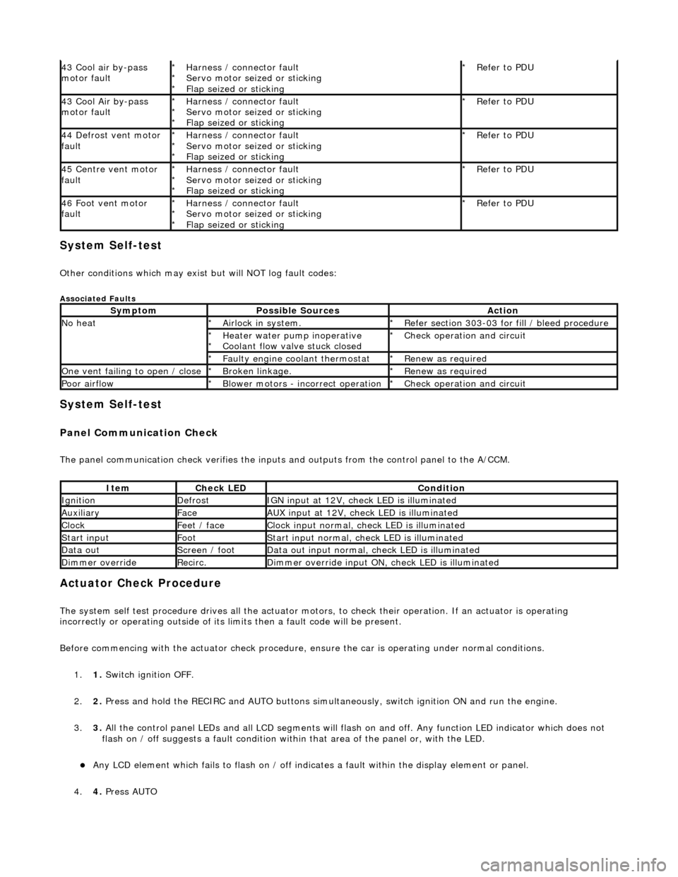
System Self-test
Other conditions which may exist but will NOT log fault codes:
Associated Faults
System Self-test
Panel Communication Check
The panel communication check veri fies the inputs and outputs from the control panel to the A/CCM.
Actuator Check Procedure
The system self test procedure drives all the actuator moto rs, to check their operation. If an actuator is operating
incorrectly or operating outside of its limi ts then a fault code will be present.
Before commencing with the actuator check procedure, ensure the ca r is operating under normal conditions.
1. 1. Switch ignition OFF.
2. 2. Press and hold the RECIRC and AUTO buttons simult aneously, switch ignition ON and run the engine.
3. 3. All the control panel LEDs and all LCD segments will flas h on and off. Any function LED indicator which does not
flash on / off suggests a fault condition within that area of the panel or, with the LED.
Any LCD element which fails to flash on / off indicates a fault within the display element or panel.
4. 4. Press AUTO
43 Cool air by-pass
motor faultHarness / connector fault
Servo motor seized or sticking
Flap seized or sticking
*
*
*Refer to PDU
*
43 Cool Air by-pass
motor faultHarness / connector fault
Servo motor seized or sticking
Flap seized or sticking
*
*
*Refer to PDU
*
44 Defrost vent motor
faultHarness / connector fault
Servo motor seized or sticking
Flap seized or sticking
*
*
*Refer to PDU
*
45 Centre vent motor
faultHarness / connector fault
Servo motor seized or sticking
Flap seized or sticking
*
*
*Refer to PDU
*
46 Foot vent motor
faultHarness / connector fault
Servo motor seized or sticking
Flap seized or sticking
*
*
*Refer to PDU
*
SymptomPossible SourcesAction
No heatAirlock in system.
*Refer section 303-03 for fill / bleed procedure
*
Heater water pump inoperative
Coolant flow valve stuck closed
*
*Check operation and circuit
*
Faulty engine coolant thermostat
*Renew as required
*
One vent failing to open / closeBroken linkage.
*Renew as required
*
Poor airflowBlower motors - incorrect operation
*Check operation and circuit
*
ItemCheck LEDCondition
IgnitionDefrostIGN input at 12V, check LED is illuminated
AuxiliaryFaceAUX input at 12V, check LED is illuminated
ClockFeet / faceClock input normal, check LED is illuminated
Start inputFootStart input normal, check LED is illuminated
Data outScreen / footData out input normal, check LED is illuminated
Dimmer overrideRecirc.Dimmer override input ON, check LED is illuminated
Page 1839 of 2490
5.5. Press RECIRC button to instigate actuator check mode.
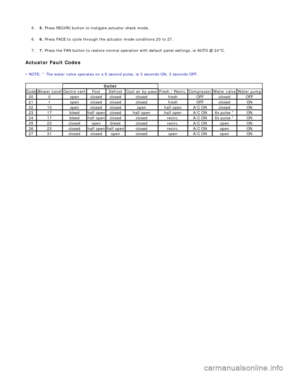
6. 6. Press FACE to cycle through the actu ator mode conditions 20 to 27.
7. 7. Press the FAN button to restore normal operation with default panel settings, ie AUTO @ 24°C.
Actuator Fault Codes
• NOTE: * The water valve operates on a 6 second pulse, ie 3 seconds ON, 3 seconds OFF.
Outlet
Code Blower Level Centre vent Foot Defrost Cool air by-pass Fresh / Recirc. Compressor Water valve Water pump
200openclosedclosedclosedfreshOFFclosedOFF
211openclosedclosedclosedfreshOFFclosedON
2210openclosedclosedopenhalf openA/C ONclosedON
2317bleedhalf openclosedhalf openhalf openA/C ON6s pulse * ON
2417bleedhalf openclosedclosedrecirc.A/C ON6s pulse * ON
2523closedopenbleedclosedrecirc.A/C ONopenON
2623closedhalf openhalf openclosedrecirc.A/C ONopenON
2731closedclosedopenclosedopenA/C ONopenON
Page 1897 of 2490
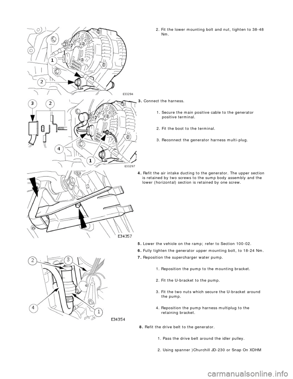
2. Fit the lower mounting bolt and nut, tighten to 38-48
Nm.
3. Connect the harness.
1. Secure the main positive cable to the generator positive terminal.
2. Fit the boot to the terminal.
3. Reconnect the generator harness multi-plug.
4. Refit the air intake ducting to the generator. The upper section
is retained by two screws to the sump body assembly and the
lower (horizontal) section is retained by one screw.
5. Lower the vehicle on the ramp ; refer to Section 100-02.
6. Fully tighten the generator upper mounting bolt, to 18-24 Nm.
7. Reposition the superc harger water pump.
1. Reposition the pump to the mounting bracket.
2. Fit the U-bracket to the pump.
3. Fit the two nuts which secure the U-bracket around the pump.
4. Reposition the pump harness multiplug to the retaining bracket.
8. Refit the drive belt to the generator.
1. Pass the drive belt around the idler pulley.
2. Using spanner )Churchill JD-230 or Snap On XDHM
Page 1976 of 2490
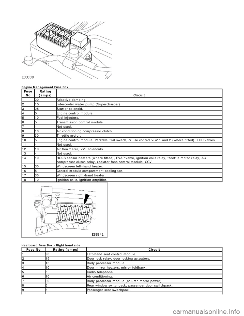
Engine Management Fuse Box
Heelboard Fuse Box - Right hand side
Fuse NoRating
(amps)Circuit
120Adaptive damping
215Intercooler water pump (Supercharger)
325Starter solenoid.
45Engine control module.
510Fuel injectors.
65Transmission control module
7-Not used.
810Air conditioning compressor clutch.
930Throttle motor.
105Engine control module, Park/Neutr al switch, cruise control VSV 1 and 2 (where fitted), EGR valves.
11-Not used.
1210Air flowmeter, VVT solenoids.
13-Not used.
1410HO2S sensor heaters (where fitted ), EVAP valve, ignition coils relay, throttle motor relay, AC
compressor clutch relay, radi ator fans control module, CCV.
1530Windscreen left-hand heater.
165Control module compartment cooling fan.
1730Windscreen right-hand heater.
1810Ignition coils, ignition amplifier.
Fuse NoRating (amps)Circuit
120Left-hand seat control module.
215Door lock relay, door locking actuators.
315Body processor module.
410Door mirror heaters, mirror foldback.
55Radio telephone.
610Air conditioning.
720Body processor module (column motor power).
85Rear window switchpack, passenger door switchpack.
95Passenger seat switchpack.