Page 924 of 2490

Engine Cooling
- Engine Cooling
Descr
i
ption and Operation
Engine Cooling Comp onents - Normally Aspirated Vehicles
Engine cooling is via a low volume, high velocity system which achieves a very fast warm up. The temperature of the
combustion chambers is reduced along with a more even temperature distribution. The temperature of the bores is increased.
F r
om the pump, coolant flows into each bank of the cylinder bl
ock. In each bank, approximately 50% of the coolant cools the
cylinder bores and the remainder is diverted th rough the bypass gallery to the cylinder head.
With the thermostat closed, coolant returns directly to the pump through the bypass on the thermostat housing.
With the thermostat open, coolant returns to the pump via the radiator.
The cooling system uses a mixture of water and Jaguar Anti-Freeze/Inhibitor (Dow 542).
The cooling system on a supercharged engine is similar, but has additional components for cooling the intake air.
Engine Cooling Co mponents - Supercharged Vehicles
ItemDescrip
tion
1Thr
ottle B
ody
2Hea
ter Return
3Coolant Pum p
4Ther
mostat Housing
5Vehicle Radia
t
or
6Hea
ter Su
pply
7Bleed
Outl
et (to expansion tank)
8EGR V
a
lve (when fitted)
9Bleed
Outl
et (to expansion tank)
Page 927 of 2490
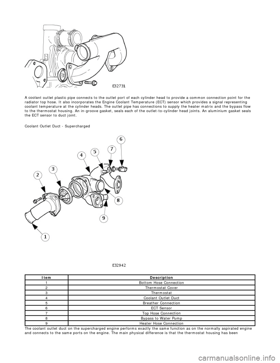
A coola
nt outlet plastic pipe connects to the outlet port of ea
ch cylinder head to provide a common connection point for the
radiator top hose. It also incorporates the Engine Coolant Te mperature (ECT) sensor which provides a signal representing
coolant temperature at the cylinder heads. The outlet pipe has connections to supply the heater matrix and the bypass flow
to the thermostat housing. An in-groove ga sket, seals each of the outlet-to-cylinder head joints. An aluminium gasket seals
the ECT sensor to duct joint.
Coolant Outlet Duct - Supercharged
The coolant outlet duct on the supercharged engine performs exactly the same function as on the normally aspirated engine
and connects to the same ports on the engine. The main physical difference is that the thermostat housing has been
ItemDe
scription
1Bottom
Hose Connection
2The
rmostat Cover
3The
rmostat
4Coolan
t Outlet Duct
5B
reather Connection
6ECT Se
nsor
7Top Hose Conn
ection
8Bypa
ss to Water Pump
9Hea
ter Hose Connection
Page 1052 of 2490
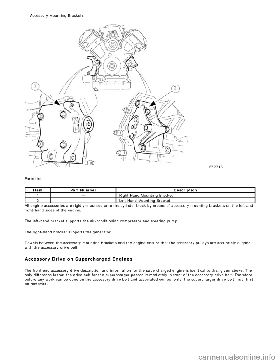
P a
rts List
All engine accessories are rigidly-mounted onto the cylinder block by means of accessory moun ting brackets on the left and
right-hand sides of the engine.
The left-hand bracket supports the air-cond itioning compressor and steering pump.
The right-hand bracket su pports the generator.
Dowels between the accessory mounting br ackets and the engine ensure that the accessory pulleys are accurately aligned
with the accessory drive belt.
A ccess
ory Drive on Supercharged Engines
The front
en
d accessory drive description and information for the
supercharged engine is identical to that given above. The
only difference is that the drive belt for the supercharger passes im mediately in front of the accessory drive belt. Therefore,
before any work can be done on the acce ssory drive belt and associated components, the supercharg er drive belt must first
be removed.
It e
m
Par
t
Number
De
scr
iption
1—R
i
ght Hand Mounting Bracket
2—Left H
and Mounting Bracket
Access
ory Mounting Brackets
Page 1115 of 2490
is at
tached to the three mounting bosses between the V of the cylinder block
has a fil
led for life inte
rnal lubrication system
is po
sitively aligned with the drive
belt by a doweled mounting bracket
C
harge Air Cooler System
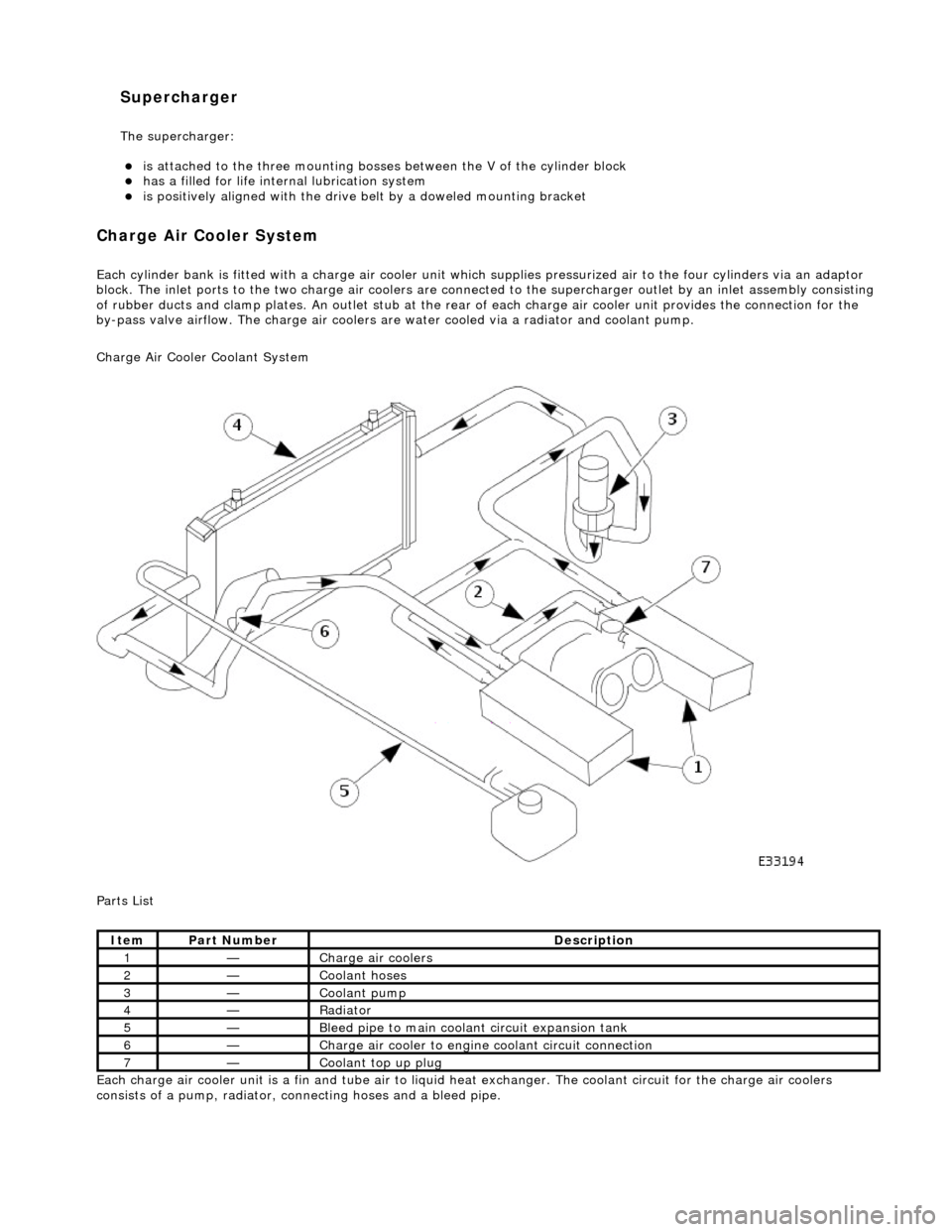
Each cyl
inder bank is fitted with a charge air cooler unit wh
ich supplies pressurized air to the four cylinders via an adaptor
block. The inlet ports to the tw o charge air coolers are connected to the supercharger outlet by an inle t assembly consisting
of rubber ducts and clamp plates . An outlet stub at the rear of each charge air cooler unit provides the connection for the
by-pass valve airflow. The charge air coolers ar e water cooled via a radiator and coolant pump.
Charge Air Cooler Coolant System
Parts List
Each charge air cooler unit is a fin and tube air to liquid heat exchanger. The coolant circuit for the charge air coolers
consists of a pump, ra diator, connecting hoses and a bleed pipe.
It
em
Par
t Number
De
scription
1—Charge air cool
ers
2—Coo
lant hoses
3—Coo
lant pump
4—Radi
ator
5—Ble
ed pipe to main coolant circuit expansion tank
6—Charge air cooler to en
gine
coolant circuit connection
7—Coo
lant top up plug
Supercharger
The supe
rcharger:
Page 1688 of 2490
Fuel System - General Inform
ation - Fuel System
Description an
d Operation
The fuel tank is mounted across the vehicle behind the passenger compartment bulkhead.
Fuel is drawn by the fuel pump from the tank and then supplied to the two fuel rails, via a filter.
Fuel injectors are installed in the fuel ra ils on each side of the intake manifold.
The amount of fuel injected into th e engine is controlled by the ECM.
A cross-over pipe connects the two fuel ra ils together at the front of the manifold.
A test valve in the cross-over pipe allo ws the fuel rail to be pressurized and de-pressurized during the servicing and
troubleshooting procedures.
A pressure regulator on the rear of the right fuel rail controls the pressure in the fuel rails.
A return line directs excess fuel from the pressure regulator back to the fuel tank.
Operation and service procedures
The fuel injector
s, rails, pres
sure regulator and, wher e fitted, supercharger are described in greater detail in Section 303-04
together with servicing procedures.
The fuel tank, pump, fuel level senders and fuel lines are similarly covered in Section 310-01.
Page 1692 of 2490
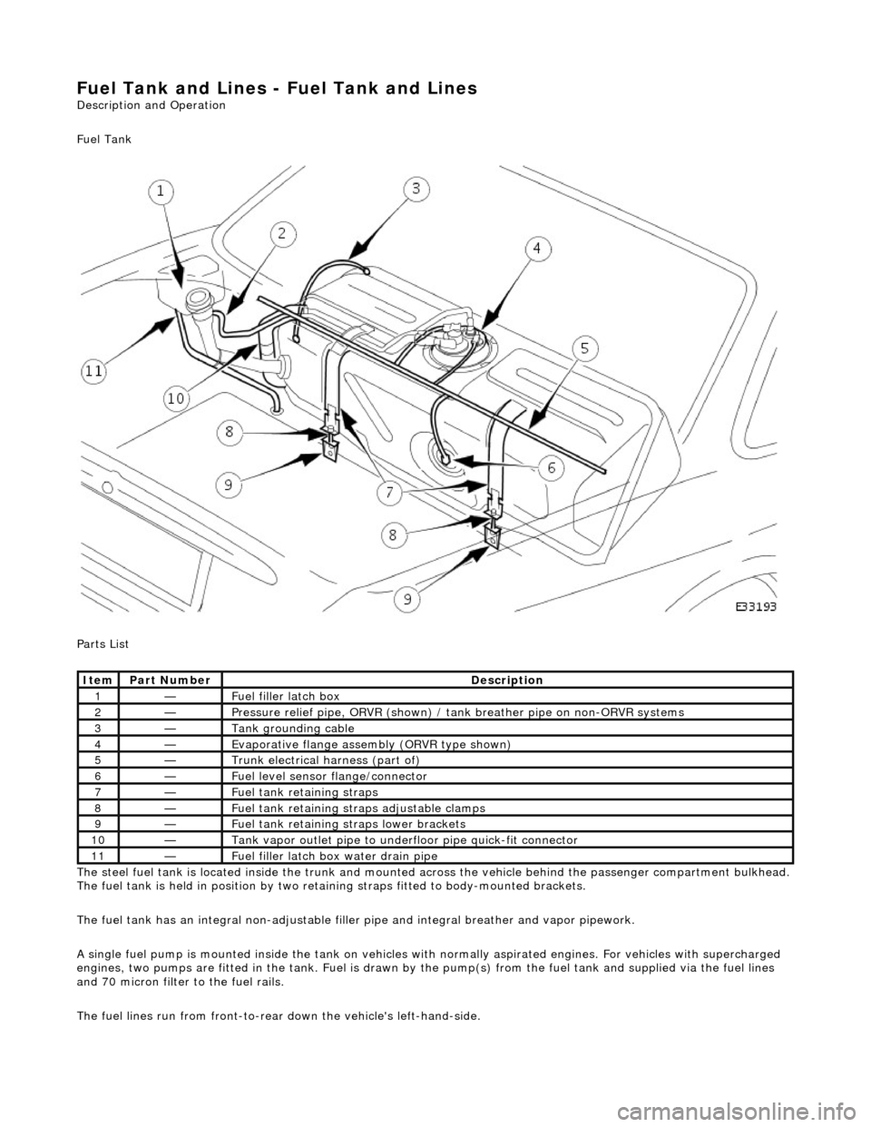
Fuel Tank and Lines - Fuel Tank and Li
nes
Description an
d Operation
Fuel Tank
Parts List
The steel fuel tank is located inside the trunk and mounted across the vehicle behind the passenger compartment bulkhead.
The fuel tank is held in posi tion by two retaining straps fi tted to body-mounted brackets.
The fuel tank has an integral non-adjustable fill er pipe and integral breather and vapor pipework.
A single fuel pump is mounted inside the tank on vehicles with normally aspirated engines. For vehicles with supercharged
engines, two pumps are fitted in the tank. Fuel is drawn by the pump(s) from the fuel tank and supplied via the fuel lines
and 70 micron filter to the fuel rails.
The fuel lines run from front-to-rear down the vehicle's left-hand-side.
Ite
m
Part
Number
Descr
iption
1—Fu
el filler latch box
2—Pressure reli
ef pipe, ORVR
(shown) / tank breather pipe on non-ORVR systems
3—Tank grounding
cable
4—Evaporative flan
ge assembly
(ORVR type shown)
5—Trunk elec
trical harne
ss (part of)
6—Fue
l
level sensor
flange/connector
7—Fu
el tank retaining straps
8—F
u
el tank retaining stra
ps adjustable clamps
9—Fu
el tank retaining straps lower brackets
10—Tank vapor outlet pipe to un
derflo
or pipe quick-fit connector
11—F
u
el filler latch bo
x water drain pipe
Page 1760 of 2490
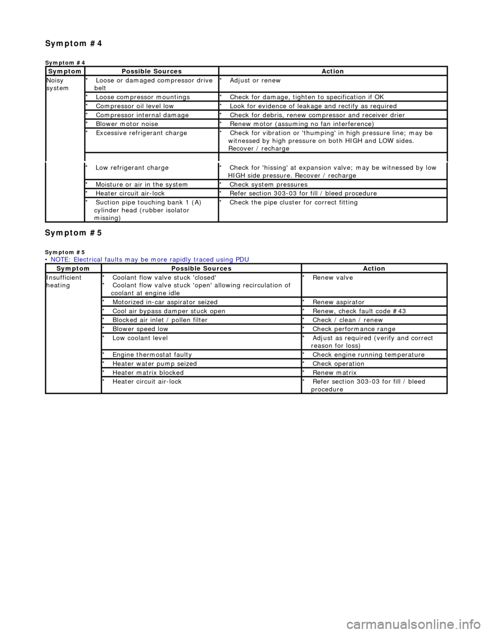
Symp
tom #5
Sy
m
ptom #5
Low r
e
frigerant charge
*
Check f or 'hissi
ng' at expansion
valve; may be witnessed by low
HIGH side pressure. Recover / recharge
*
Moi
s
ture or air in the system
*
Chec k syst
em pressures
*
Heat er ci
rcuit air-lock
*
R e
fer section 303-03 for fill / bleed procedure
*
Suct ion
pipe touching bank 1 (A)
cylinder head (rubber isolator
missing)
*
Check the pi
pe cluster for correct fitti
ng
*
• NOTE: Electrical faults may be more rapidly traced using PDU
Sym
ptom
Possib
l
e Sources
Acti
o
n
Insuffi
ci
ent
heating
Coo l
ant flow valve stuck 'closed'
Coolant flow valve stuck 'open' allowing recirculation of
coolant at engine idle
*
*
Re
new v
alve
*
Motorized in-car aspirator sei zed
*R e
new aspirator
*
Coo l
air bypass damper stuck open
*
Re new,
check fault code #43
*
B l
ocked air inlet / pollen filter
*
Chec k / cl
ean / renew
*
B l
ower speed low
*
Check performance range
*
Low cool ant
level
*
Adjust as req u
ired (verify and correct
reason for loss)
*
Engine
t
hermostat faulty
*
Check engine r u
nning temperature
*
Heater water pump seized
*Chec k op
eration
*
Heater ma trix
blocked
*
Re new m
atrix
*
Heater circui t
air-lock
*
R e
fer section 303-03 for fill / bleed
procedure
*
Sym
p
tom #4
Sym
ptom #4
Sy
m
ptom
Possib
l
e Sources
Acti
o
n
No
i
sy
system
Loose or damaged compressor drive
belt
*Adjust or r
e
new
*
Loose compressor mountings
*Check f o
r damage, tighten to specification if OK
*
Compressor oil level l
ow
*
Look for evidence of l
eakag
e and rectify as required
*
Compressor internal dama ge
*Check f o
r debris, renew compressor and receiver drier
*
B l
ower motor noise
*
Re new m
otor (assuming no fan interference)
*
Excessive refrige rant charge
*Check f o
r vibration or 'thumping'
in high pressure line; may be
witnessed by high pressure on both HIGH and LOW sides.
Recover / recharge
*
Page 1783 of 2490
Heating and Ventilation - Heating and Ventilation
Description and Operation
Schematic Diagram
Parts List
Heater System Components
ItemPart NumberDescription
1—Heater matrix
2—Firewall
3—Non return valve
4—Water pump
5—Water valve
6—Return to engine
7—Feed from engine
8—Non return valve (heater bypass)