Page 1513 of 2490
Automatic Transmission/Transaxle External Contro ls - 4.0L SC V8 - AJ26 -
Selector Lever Cable and Bracket
Removal and Installation
Removal
1. Disconnect the vehicle battery ground lead.
2. Position the selector to N.
3. Remove the J-gate surround, Section 501-05.
4. Remove the console finisher ve neer panel, Section 501-12.
5. Remove the center console assembly, Section 501-12.
6. Raise the vehicle for access.
7. Detach the gear selector cable from the transmission unit.
1. Remove the nut which secures the selector cable ball pin to the selector lever.
2. Lower the transmissi on lift for access.
3. Remove the bolts which secure the selector cable to the transmission casing.
8. Reposition the selector cable.
9. Remove the LH front seat, Section 501-10.
10. Reposition the LH floo r carpet for access.
11. Remove the selector cable to tunnel clip tie strap.
12. Detach the selector cable from the gear shift assembly.
1. Remove the inner cable to shift lever nut.
Page 1517 of 2490
Automatic Transmission/Transaxle External Contro ls - 4.0L SC V8 - AJ26 -
Selector Lever Indicator Disc
Removal and Installation
Removal
Installation
1.
Disconnect the vehicle battery ground lead.
2. Remove the selector indicator module; Operation 44.15.14.
3. Remove the selector indicator module disc.
Remove the disc retaining screw.
1. Installation is th e reverse of the re moval procedure.
Page 1518 of 2490

Automatic Transmission/Transaxle External Contro ls - 4.0L SC V8 - AJ26 -
Transmission Control Switch (TCS)
Removal and Installation
Removal
Installation
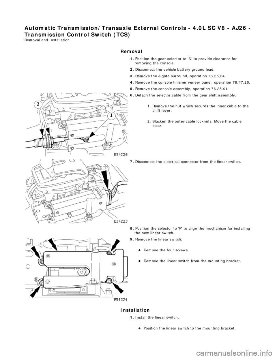
1. Position the gear selector to 'N' to provide clearance for
removing the console.
2. Disconnect the vehicle battery ground lead.
3. Remove the J-gate surroun d, operation 76.25.24.
4. Remove the console finisher vene er panel, operation 76.47.26.
5. Remove the console assembly, operation 76.25.01.
6. Detach the selector cable from the gear shift assembly.
1. Remove the nut which secures the inner cable to the shift lever.
2. Slacken the outer cable locknuts. Move the cable clear.
7. Disconnect the electrical conne ctor from the linear switch.
8. Position the selector to 'P' to align the mechanism for installing
the new linear switch.
9. Remove the linear switch.
Remove the four screws.
Remove the linear switch fro m the mounting bracket.
1. Install the linear switch.
Position the linear switch to the mounting bracket.
Page 1521 of 2490
Automatic Transmission/Transaxle External Contro ls - 4.0L SC V8 - AJ26 -
Selector Lever Knob
Removal and Installation
Removal
Installation
1.
Disconnect the vehicle battery ground lead.
2. Remove the select or lever knob.
1. Slacken the ferrule, rotate clockwise.
2. Rotate the knob coun ter-clockwise to remove.
1. Refer to the illustration.
1. Fit the knob.
2. Refer to the illustration.
Page 1533 of 2490

Exhaust System - Exhaust System
Diagnosis and Testing
Symptom Chart
Symptom Chart
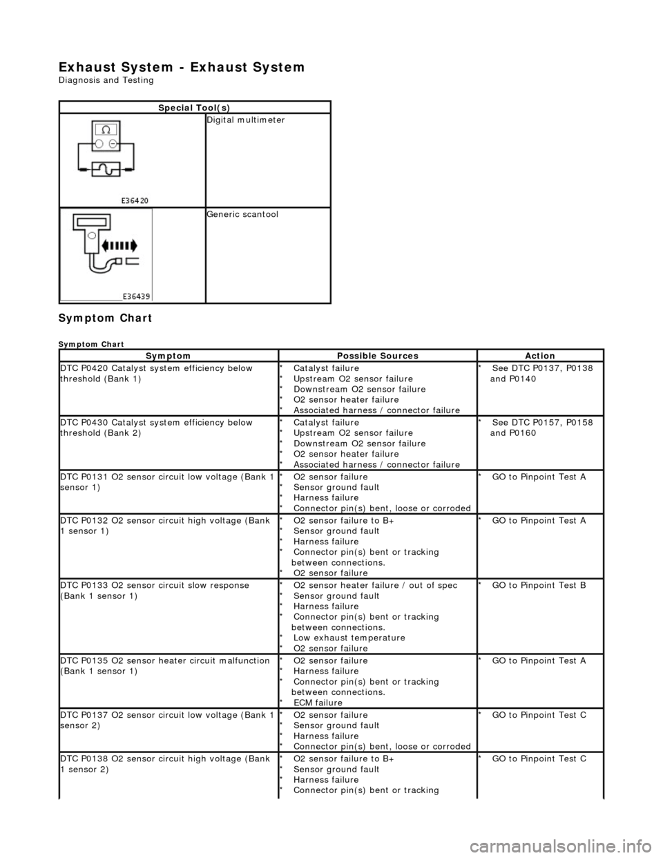
Special Tool(s)
Digital multimeter
Generic scantool
SymptomPossible SourcesAction
DTC P0420 Catalyst system efficiency below
threshold (Bank 1)Catalyst failure
Upstream O2 sensor failure
Downstream O2 sensor failure
O2 sensor heater failure
Associated harness / connector failure
*
*
*
*
*See DTC P0137, P0138
and P0140
*
DTC P0430 Catalyst system efficiency below
threshold (Bank 2)Catalyst failure
Upstream O2 sensor failure
Downstream O2 sensor failure
O2 sensor heater failure
Associated harness / connector failure
*
*
*
*
*See DTC P0157, P0158
and P0160
*
DTC P0131 O2 sensor circuit low voltage (Bank 1
sensor 1)O2 sensor failure
Sensor ground fault
Harness failure
Connector pin(s) bent, loose or corroded
*
*
*
*GO to Pinpoint Test A
*
DTC P0132 O2 sensor circuit high voltage (Bank
1 sensor 1)O2 sensor failure to B+
Sensor ground fault
Harness failure
Connector pin(s) bent or tracking
between connections. O2 sensor failure
*
*
*
*
*GO to Pinpoint Test A
*
DTC P0133 O2 sensor circuit slow response
(Bank 1 sensor 1)O2 sensor heater failure / out of spec
Sensor ground fault
Harness failure
Connector pin(s) bent or tracking
between connections. Low exhaust temperature
O2 sensor failure
*
*
*
*
*
*GO to Pinpoint Test B
*
DTC P0135 O2 sensor heater circuit malfunction
(Bank 1 sensor 1)O2 sensor failure
Harness failure
Connector pin(s) bent or tracking
between connections. ECM failure
*
*
*
*GO to Pinpoint Test A
*
DTC P0137 O2 sensor circuit low voltage (Bank 1
sensor 2)O2 sensor failure
Sensor ground fault
Harness failure
Connector pin(s) bent, loose or corroded
*
*
*
*GO to Pinpoint Test C
*
DTC P0138 O2 sensor circuit high voltage (Bank
1 sensor 2)O2 sensor failure to B+
Sensor ground fault
Harness failure
Connector pin(s) bent or tracking
*
*
*
*GO to Pinpoint Test C
*
Page 1534 of 2490

Pinpoint test A: P0131, P0132, P0135
between connections. ECM failure
*
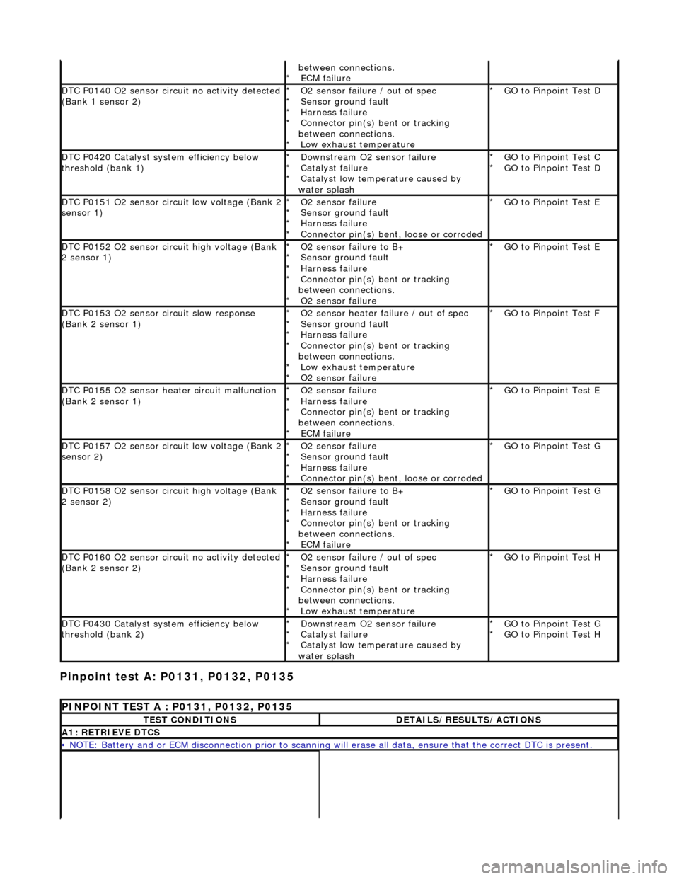
DTC P0140 O2 sensor circuit no activity detected
(Bank 1 sensor 2)O2 sensor failure / out of spec
Sensor ground fault
Harness failure
Connector pin(s) bent or tracking
between connections. Low exhaust temperature
*
*
*
*
*GO to Pinpoint Test D
*
DTC P0420 Catalyst system efficiency below
threshold (bank 1)Downstream O2 sensor failure
Catalyst failure
Catalyst low temperature caused by
water splash
*
*
*GO to Pinpoint Test C
GO to Pinpoint Test D
*
*
DTC P0151 O2 sensor circuit low voltage (Bank 2
sensor 1)O2 sensor failure
Sensor ground fault
Harness failure
Connector pin(s) bent, loose or corroded
*
*
*
*GO to Pinpoint Test E
*
DTC P0152 O2 sensor circuit high voltage (Bank
2 sensor 1)O2 sensor failure to B+
Sensor ground fault
Harness failure
Connector pin(s) bent or tracking
between connections. O2 sensor failure
*
*
*
*
*GO to Pinpoint Test E
*
DTC P0153 O2 sensor circuit slow response
(Bank 2 sensor 1)O2 sensor heater failure / out of spec
Sensor ground fault
Harness failure
Connector pin(s) bent or tracking
between connections. Low exhaust temperature
O2 sensor failure
*
*
*
*
*
*GO to Pinpoint Test F
*
DTC P0155 O2 sensor heater circuit malfunction
(Bank 2 sensor 1)O2 sensor failure
Harness failure
Connector pin(s) bent or tracking
between connections. ECM failure
*
*
*
*GO to Pinpoint Test E
*
DTC P0157 O2 sensor circuit low voltage (Bank 2
sensor 2)O2 sensor failure
Sensor ground fault
Harness failure
Connector pin(s) bent, loose or corroded
*
*
*
*GO to Pinpoint Test G
*
DTC P0158 O2 sensor circuit high voltage (Bank
2 sensor 2)O2 sensor failure to B+
Sensor ground fault
Harness failure
Connector pin(s) bent or tracking
between connections. ECM failure
*
*
*
*
*GO to Pinpoint Test G
*
DTC P0160 O2 sensor circuit no activity detected
(Bank 2 sensor 2)O2 sensor failure / out of spec
Sensor ground fault
Harness failure
Connector pin(s) bent or tracking
between connections. Low exhaust temperature
*
*
*
*
*GO to Pinpoint Test H
*
DTC P0430 Catalyst system efficiency below
threshold (bank 2)Downstream O2 sensor failure
Catalyst failure
Catalyst low temperature caused by
water splash
*
*
*GO to Pinpoint Test G
GO to Pinpoint Test H
*
*
PINPOINT TEST A : P0131, P0132, P0135
TEST CONDITIONSDETAILS/RESULTS/ACTIONS
A1: RETRIEVE DTCS
• NOTE: Battery and or ECM disconnection prior to scanning wi
ll erase all data, ensure that the correct DTC is present.
Page 1536 of 2490
Bracket on top of gearbox or Bulkhead rear of engine
With EM021 disconnected, measure the voltage between
EM021/003 and EM021/004. 3
Is the voltage between 600mV and 1.0 Volt?
Yes
GO to A4
No Renew O2 sensor; reconnect plug(s)
GO to A6
A4: CHECK FOR O2 SENSOR FAILURE
With the conditions held as A3, suddenly decelerate to idle. 1
Has the voltage dropped to 400mV or less ?
Yes GO to A5
No Renew O2 sensor; reconnect plug(s)
GO to A6
A5: CHECK FOR O2 SENSOR FAILURE
With the conditions held as A4, suddenly accelerate to
approximately 2500 rpm. 1
Has the voltage risen to between 600mV and 1 volt?
Yes GO to A7
No Renew O2 sensor; reconnect plug(s)
GO to A6
A6: STOP
Perform appropriate service drive cycle and check for the
presence of DTC 1
Has the fault code cleared?
Yes STOP
No Contact Jaguar Service
A7: HEATED O2 SENSOR SHORT CIRCUIT TO GROUND
Page 1537 of 2490
Measure the insulation resistance between sensor pin 001
and sensor body 1
Repeat for pin 003 and sensor body 2
Is the resistance > 10 MOHM?
Yes GO to A9
No Renew the O2 sensor and reconnect plug(s)
GO to A8
A8: STOP
Perform appropriate service drive cycle and check for the
presence of DTC 1
Has the fault code cleared?
Yes STOP
No Contact Jaguar Service
A9: SIGNAL GROUND 1 CONTINUITY