1998 JAGUAR X308 oil
[x] Cancel search: oilPage 1759 of 2490
Sym
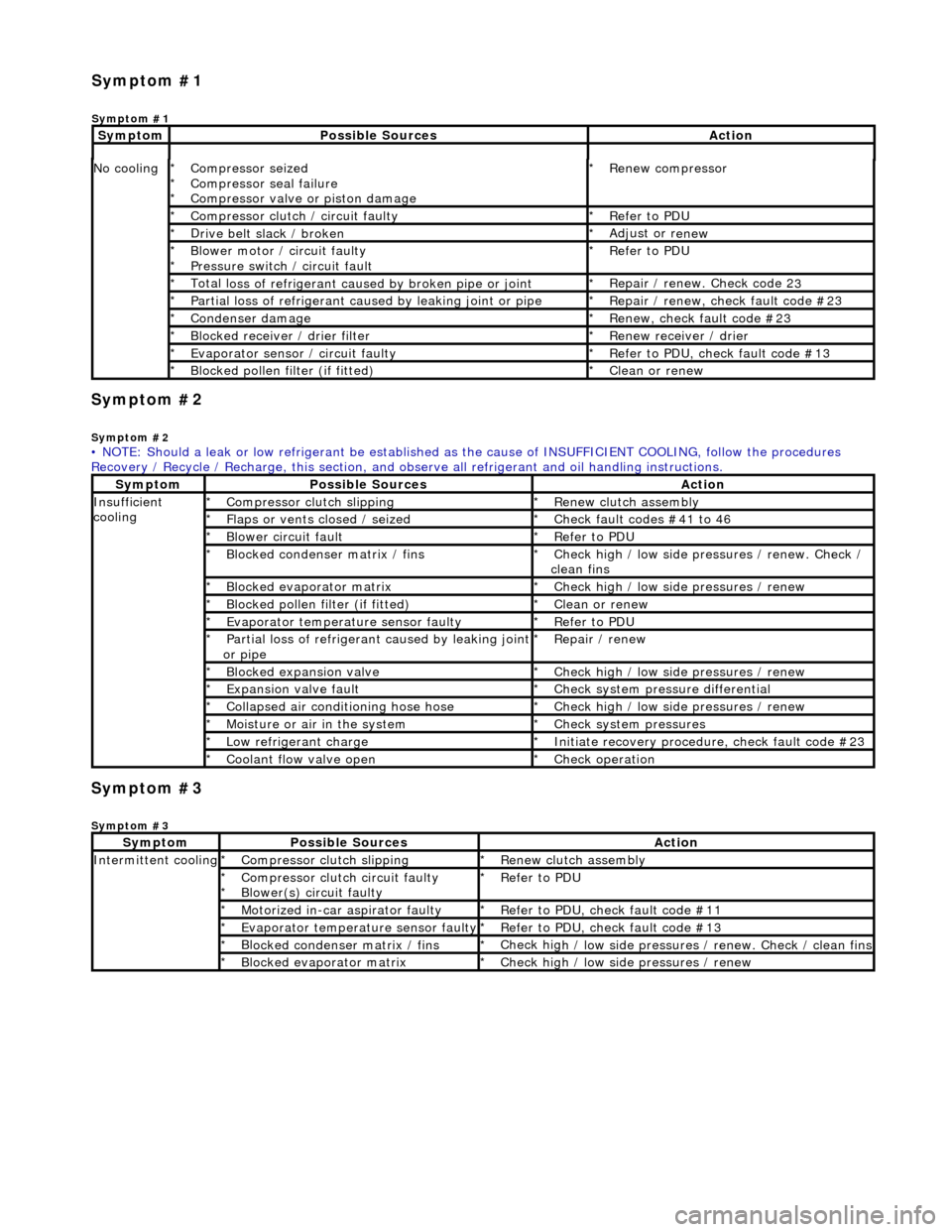
ptom #2
Sy
mptom #2
Sym
ptom #3
Sy
mptom #3
No
cooling
Compressor sei
zed
Compressor seal failure
Compressor valve or piston damage
*
*
*
R
enew compressor
*
Compressor cl
utch / circuit faulty
*
R
efer to PDU
*
D
rive belt slack / broken
*
Adjust or r
enew
*
B
lower motor / circuit faulty
Pressure switch / circuit fault
*
*
R
efer to PDU
*
Total l
oss of refrigerant caused by broken pipe or joint
*
Repair / renew. Check code 2
3
*
P
artial loss of refrigerant caused by leaking joint or pipe
*
R
epair / renew, check fault code #23
*
Conden
ser damage
*
Re
new, check fault code #23
*
Bl
ocked receiver / drier filter
*
R
enew receiver / drier
*
Evaporator senso
r / circuit faulty
*
R
efer to PDU, check fault code #13
*
Bl
ocked pollen filter (if fitted)
*
Cle
an or renew
*
• NOTE: Should a leak or low refrigerant be established as the cause of INSUFFICIENT COOL ING, follow the procedures
Recovery / Recycle / Recharge, this section, and ob serve all refrigerant and oil handling instructions.
Sy
mptom
Possib
le Sources
Acti
on
Insuffi
cient
cooling
Compre
ssor clutch slipping
*
R
enew clutch assembly
*
Fl
aps or vents closed / seized
*
Check f
ault codes #41 to 46
*
Bl
ower circuit fault
*
R
efer to PDU
*
Bl
ocked condenser matrix / fins
*
Check hig
h / low side pr
essures / renew. Check /
clean fins
*
Bl
ocked evaporator matrix
*
Check hig
h / low side
pressures / renew
*
Bl
ocked pollen filter (if fitted)
*
Cle
an or renew
*
Evaporator temp
erat
ure sensor faulty
*
R
efer to PDU
*
P
artial loss of refrigerant caused by leaking joint
or pipe
*
R
epair / renew
*
Blocked expan
sion valve
*
Check hig
h / low side
pressures / renew
*
Expans
ion valve fault
*
Chec
k system pres
sure differential
*
C
ollapsed air conditioning hose hose
*
Check hig
h / low side
pressures / renew
*
Moi
sture or air in the system
*
Chec
k system pressures
*
Low r
efrigerant charge
*
Initiate recovery
procedure, check fault code #23
*
Coo
lant flow valve open
*
Chec
k operation
*
Sy
mptom
Possib
le Sources
Acti
on
Int
ermittent cooling
Compre
ssor clutch slipping
*
R
enew clutch assembly
*
Compressor cl
utch circuit faulty
Blower(s) circuit faulty
*
*
R
efer to PDU
*
Motorized in-car aspirator faulty
*
R
efer to PDU, check fault code #11
*
Evaporator temp
erature sensor faulty
*
R
efer to PDU, check fault code #13
*
Bl
ocked condenser matrix / fins
*
Check hig
h / low side pressures / renew. Check / clean fins
*
Bl
ocked evaporator matrix
*
Check hig
h / low side
pressures / renew
*
Sym
ptom #1
Sy
mptom #1
Sy
mptom
Possib
le Sources
Acti
on
Page 1760 of 2490
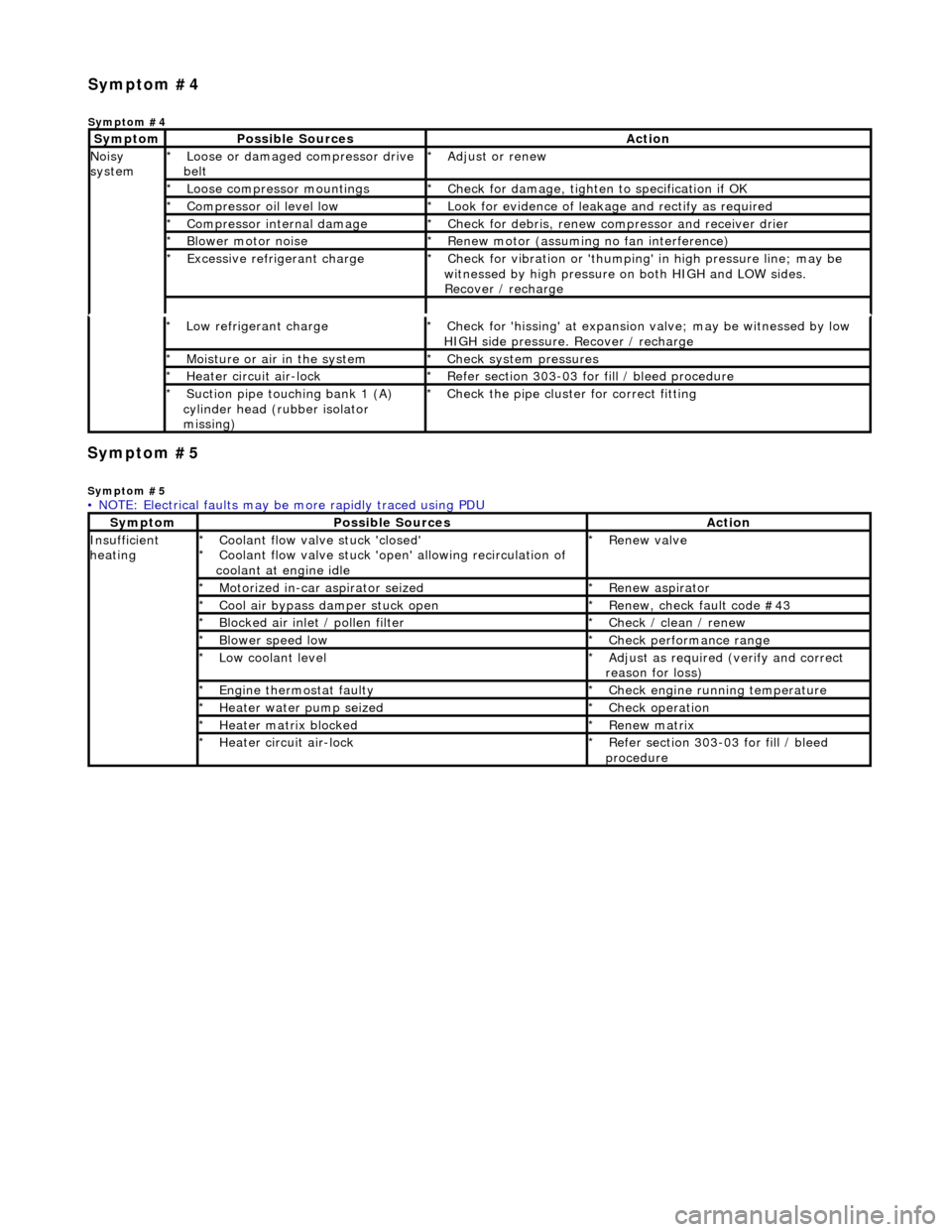
Symp
tom #5
Sy
m
ptom #5
Low r
e
frigerant charge
*
Check f or 'hissi
ng' at expansion
valve; may be witnessed by low
HIGH side pressure. Recover / recharge
*
Moi
s
ture or air in the system
*
Chec k syst
em pressures
*
Heat er ci
rcuit air-lock
*
R e
fer section 303-03 for fill / bleed procedure
*
Suct ion
pipe touching bank 1 (A)
cylinder head (rubber isolator
missing)
*
Check the pi
pe cluster for correct fitti
ng
*
• NOTE: Electrical faults may be more rapidly traced using PDU
Sym
ptom
Possib
l
e Sources
Acti
o
n
Insuffi
ci
ent
heating
Coo l
ant flow valve stuck 'closed'
Coolant flow valve stuck 'open' allowing recirculation of
coolant at engine idle
*
*
Re
new v
alve
*
Motorized in-car aspirator sei zed
*R e
new aspirator
*
Coo l
air bypass damper stuck open
*
Re new,
check fault code #43
*
B l
ocked air inlet / pollen filter
*
Chec k / cl
ean / renew
*
B l
ower speed low
*
Check performance range
*
Low cool ant
level
*
Adjust as req u
ired (verify and correct
reason for loss)
*
Engine
t
hermostat faulty
*
Check engine r u
nning temperature
*
Heater water pump seized
*Chec k op
eration
*
Heater ma trix
blocked
*
Re new m
atrix
*
Heater circui t
air-lock
*
R e
fer section 303-03 for fill / bleed
procedure
*
Sym
p
tom #4
Sym
ptom #4
Sy
m
ptom
Possib
l
e Sources
Acti
o
n
No
i
sy
system
Loose or damaged compressor drive
belt
*Adjust or r
e
new
*
Loose compressor mountings
*Check f o
r damage, tighten to specification if OK
*
Compressor oil level l
ow
*
Look for evidence of l
eakag
e and rectify as required
*
Compressor internal dama ge
*Check f o
r debris, renew compressor and receiver drier
*
B l
ower motor noise
*
Re new m
otor (assuming no fan interference)
*
Excessive refrige rant charge
*Check f o
r vibration or 'thumping'
in high pressure line; may be
witnessed by high pressure on both HIGH and LOW sides.
Recover / recharge
*
Page 1761 of 2490
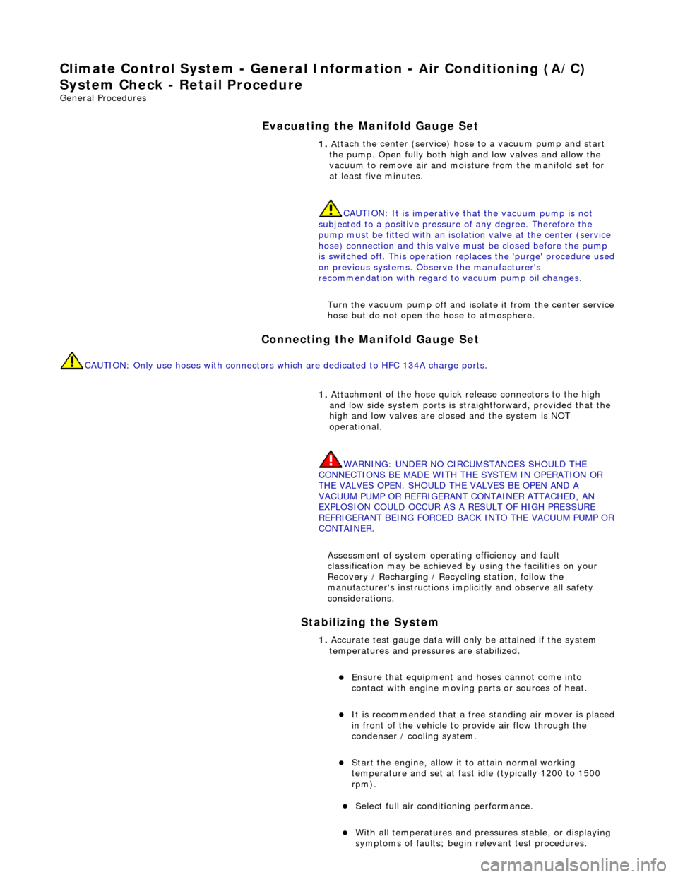
Climate Co
ntrol System - General In
formation - Air Conditioning (A/C)
System Check - Re tail Procedure
Gen
eral Procedures
E
vacuating the Manifold Gauge Set
Connecting the Manifold Gauge Set
C
AUTION: Only use hoses with connectors wh
ich are dedicated to HFC 134A charge ports.
Stabilizing the System
1.
At
tach the center (service) hose to a vacuum pump and start
the pump. Open fully both high and low valves and allow the
vacuum to remove air and mois ture from the manifold set for
at least five minutes.
CAUTION: It is imperative th at the vacuum pump is not
subjected to a positi ve pressure of any degree. Therefore the
pump must be fitted wi th an isolation valve at the center (service
hose) connection and this valve mu st be closed before the pump
is switched off. This operation replaces the 'purge' procedure used
on previous systems. Observe the manufacturer's
recommendation with regard to vacuum pump oil changes.
Turn the vacuum pump off and isol ate it from the center service
hose but do not open the hose to atmosphere.
1. Att
achment of the hose quick release connectors to the high
and low side system ports is stra ightforward, provided that the
high and low valves are closed and the system is NOT
operational.
WARNING: UNDER NO CIRCUMSTANCES SHOULD THE
CONNECTIONS BE MADE WITH THE SYSTEM IN OPERATION OR
THE VALVES OPEN. SHOULD THE VALVES BE OPEN AND A
VACUUM PUMP OR REFRIGERANT CONTAINER ATTACHED, AN
EXPLOSION COULD OCCUR AS A RESULT OF HIGH PRESSURE
REFRIGERANT BEING FORCED BACK INTO THE VACUUM PUMP OR
CONTAINER.
Assessment of system operating efficiency and fault
classification may be achieved by using the facilities on your
Recovery / Recharging / Recycling station, follow the
manufacturer's instructions implicitly and observe all safety
considerations.
1. Accurate test gauge data wi
ll on
ly be attained if the system
temperatures and pressures are stabilized.
E
nsure that equipment and hoses cannot come into
contact with engine moving parts or sources of heat.
It is recommended th at a free standing air
mover is placed
in front of the vehicle to provide air flow through the
condenser / cooling system.
St
art the engine, allow it to attain normal working
temperature and set at fast idle (typically 1200 to 1500
rpm).
Select full
air condit
ioning performance.
With
all temperatures and pres
sures stable, or displaying
symptoms of faults; begin relevant test procedures.
Page 1765 of 2490
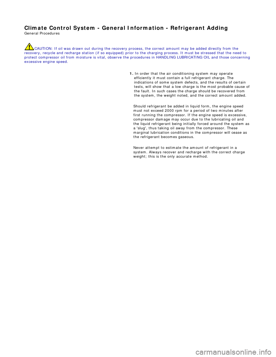
Climate Co
ntrol System - General
Information - Refrigerant Adding
Gen
eral Procedures
CAUTION: If oil was drawn out during the recovery process, the correct amount may be added directly from the
recovery, recycle and recharge station (if so equipped) prior to the charging process. It must be stressed that the need to
protect compressor oil from moisture is vital, observe the pr ocedures in HANDLING LUBRICATING OIL and those concerning
excessive engine speed.
1. In order that the
air conditioning system may operate
efficiently it must contain a full refrigerant charge. The
indications of some system defects, and the results of certain
tests, will show that a low charge is the most probable cause of
the fault. In such cases the ch arge should be recovered from
the system, the weight noted, and the correct amount added.
Should refrigerant be added in liquid form, the engine speed
must not exceed 2000 rpm for a period of two minutes after
first running the compressor. If the engine speed is excessive,
compressor damage may occur du e to the lubricating oil and
the liquid refrigerant being initia lly forced around the system as
a 'slug', thus taking oil away from the compressor. These
marginal lubrication conditions in the compressor will cease as
the refrigerant becomes gaseous.
Never attempt to estimate the amount of refrigerant in a
system. Always recover and rech arge with the correct charge
weight; this is the only accurate method.
Page 1766 of 2490
Climate Control System - General Informatio
n - Refrigerant Oil Adding
Gen
e
ral Procedures
CAUTION: Always decant fresh oil from a sealed container and do not leave oil exposed to the atmosphere. PAG oil is
very hygroscopic (absorbs wate r) and will rapidly attract atmospheric moisture. PAG oil must NEVER be mixed with mineral
based oils. Do not re-use oil following a recovery cycle, dispose of it safely.
Original Compressor
New Compressor
1. The amount of oi
l drawn out during a recovery procedure will
be dependent on the state of the system and the rate of
recovery. The quantity will be a pproximately 30 to 40 ml.; this
may vary, and the figure is given only for guidance.
The oil separator vessel in the recovery equipment must be
clean and empty at the start of the process, so that the quantity
of oil which is drawn out may be accurately measured.
• NOTE: The equipment manufactu rer's instructions must be
followed when adding oil directly into an original, or new unit,
owing to rectification work to the existing compressor, or the
need to fit a new compressor.
Oil may be added to the system either via the recovery, recycle
and recharge station or by us ing a proprietary oil injector.
Alternatively, if the compress or has been removed from the
vehicle, the oil may be added directly to the compressor.
1. From an existing compressor, drain the oil into a measuring
cylinder and record the amount. Fl ush the unit out with fresh oil
and drain thoroughly. Replenish the compressor with the same
amount of oil that was originally drained out and immediately
plug all orifices ready for refitting to the vehicle.
1. Drain and discard th e transit lubricating oil from the new
compressor before it is be fitted.
To avoid over-filling the system, an allowance must be made for
the quantity of oil found in the original compressor and the
quantity deposite d in the recovery equipment oil separator from
the charge recovery operation.
Typical example:
D rained
from original compressor - 50 ml.
R
e
covered from oil separator - 40 ml.
Q
u
antity to be put in new compressor - 50 + 40 = 90 ml.
2. The difference between the combined total quantity of
recovered and drained oil and the nominal capacity of the
system (180 ml.), is due to th e quantity of oil remaining in
components such as the cond enser, receiver drier or
evaporator. This oil is no t normally recoverable.
The same procedure may be followed if a problem has occurred
due to oil leakage, as the amount of oil lost is generally small. If
the recovery process has no t been necessary, because
refrigerant has also been lost, then only the quantity drained
from the original compress or needs to be replaced.
Page 1767 of 2490
System Compon
ents
1.
Should a major component such as
condenser, receiver drier or
evaporator be renewed, then an adjustment to the system oil
content must be made. This ma y be carried out in the same
way as the examples for the compressor, except for the fact
that trapped oil within any of these components cannot
normally be recovered. An extr a quantity of oil should be
added, in addition to that re covered from the recovery station
separator, as follows:
Conden
ser - Add 40 ml.
Evaporator -
Add 40 ml.
Receiver drier -
No addition.
Page 1805 of 2490
Installation
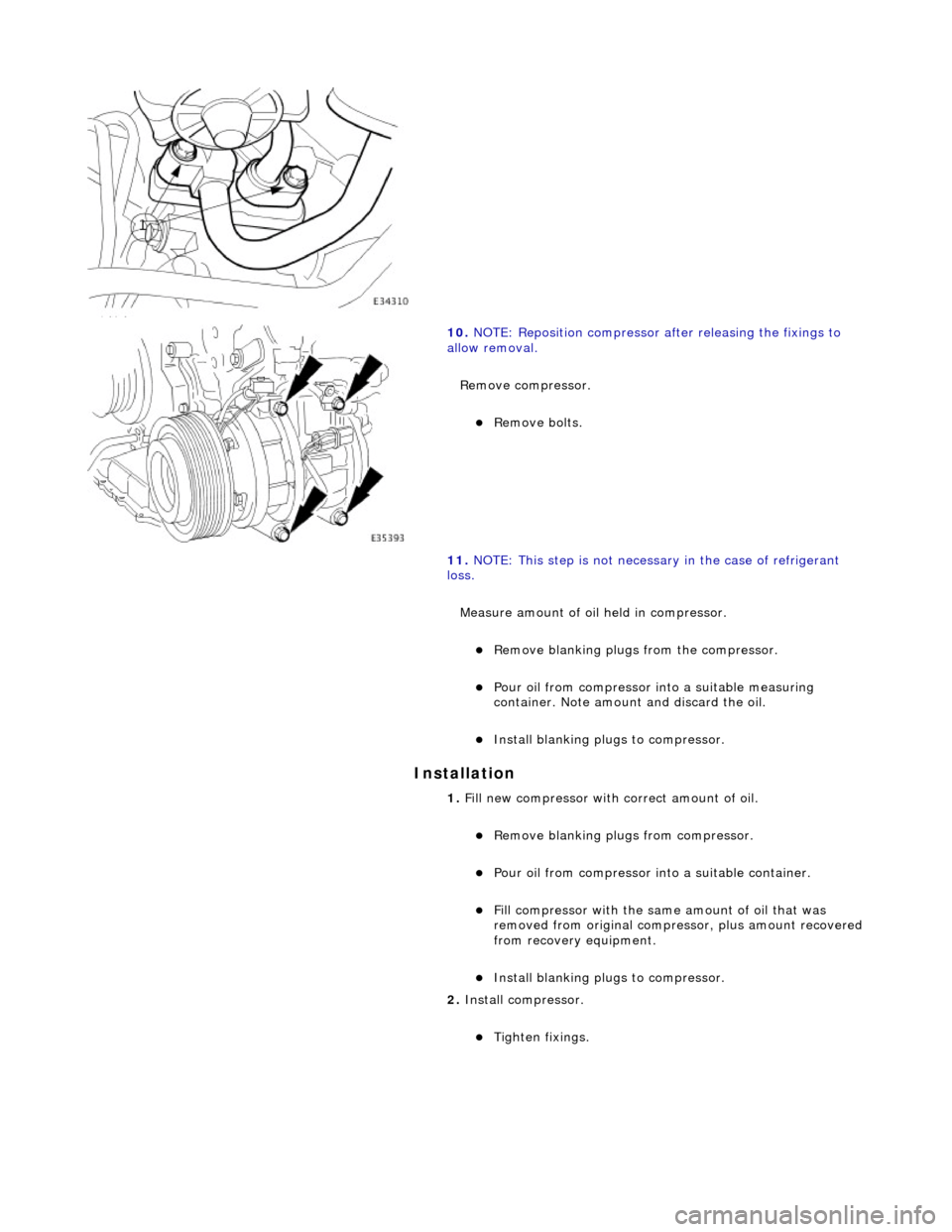
10. NOTE: Reposition compressor after releasing the fixings to
allow removal.
Remove compressor.
Remove bolts.
11. NOTE: This step is not necessar y in the case of refrigerant
loss.
Measure amount of oil held in compressor.
Remove blanking plugs from the compressor.
Pour oil from compressor into a suitable measuring
container. Note amount and discard the oil.
Install blanking plugs to compressor.
1. Fill new compressor with correct amount of oil.
Remove blanking plugs from compressor.
Pour oil from compressor into a suitable container.
Fill compressor with the same amount of oil that was
removed from original compre ssor, plus amount recovered from recovery equipment.
Install blanking plugs to compressor.
2. Install compressor.
Tighten fixings.
Page 1806 of 2490
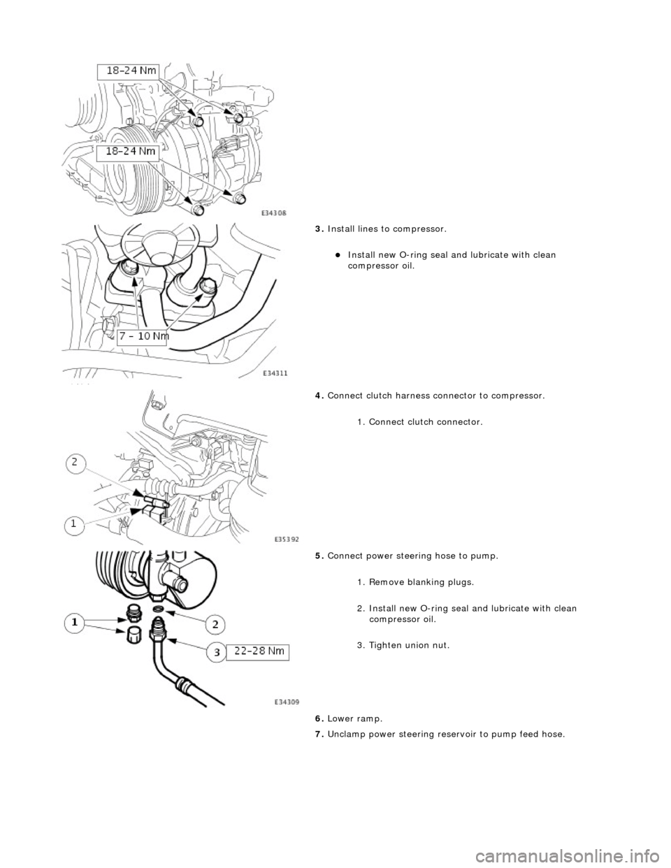
3. Install lines to compressor.
Install new O-ring seal and lubricate with clean
compressor oil.
4. Connect clutch harness connector to compressor.
1. Connect clutch connector.
5. Connect power steering hose to pump.
1. Remove blanking plugs.
2. Install new O-ring seal and lubricate with clean
compressor oil.
3. Tighten union nut.
6. Lower ramp.
7. Unclamp power steering rese rvoir to pump feed hose.