Page 1395 of 2490
and/or increased performance as appropriate.
Serial Communications Interfaces
Controller Area Network (CAN)
The TCM is an integral part of the CAN system which facilita tes the interchange of real-time data between control modules
and sensors; refer to 303-14 fo r a full description of CAN.
Transmission Pressure Regulators and Shift Solenoids Circuit Diagram
ItemPart NumberDescription
1—Transmission oil temperature sensor
2—Switch
3—Shift solenoid 1 <-> 2, 4 <-> 5
4—Shift solenoid 2 <-> 3
Page 1401 of 2490
Pinpoint test A: P0740
DTC P0730 Incorrect gear ratioEngaged gear implausible / transmission
slipping Oil level low
Valve body assembly faulty
Transmission faulty
*
*
*
*GO to Pinpoint Test H *
DTC P0780 Shift malfunctionValve body assembly faulty
Transmission faulty
*
*GO to Pinpoint Test H *
PINPOINT TEST A : P0740
TEST CONDITIONSDETAILS/RESULTS/ACTIONS
A1: RETRIEVE DTCS
• NOTE: Battery and or ECM disconnection prior to scanning wi
ll erase all data, ensure that the correct DTC is present.
Connect the scan tool 1
Have the DTC(s) and freeze frame data been recorded?
Yes GO to A2
A2: CHECK TORQUE CONVERTER CLUTCH SOLENOID RESISTANCE
With, EM062 disconnected, measure the resistance between 1
Page 1433 of 2490
Automatic Transmission/Transaxle - 4.0L SC V8 - AJ26 - Extension
Housing Seal
In-vehicle Repair
Removal
Special Tool(s)
Oil seal replacer
307-378
Driveshaft wrench
205-053
1. Disconnect the battery ground lead.
2. Select N and choc the road wheels.
3. Remove the front muffler, re fer to Operation 30.10.18.
4. Remove the engine rear mounting bracket.
1. Support the transmission.
2. Remove the bolt, engine rear mounting to transmission.
3. Remove the four bolts which secure the mounting
cross member to the body.
5. Detach the driveshaft from th e transmission drive flange.
1. If the transmission is to be refitted, mark the position of the coupling relative to the drive flange.
5. CAUTION: Under no circ umstances remove the
driveshaft to flexible coupling fixings.
2. Remove the three bolts, tr ansmission drive flange to
flexible coupling.
6. Secure the driveshaft wrench 205 - 053 to the output shaft
flange.
Page 1434 of 2490
Installation
7. Remove the output shaft flange.
1. Using a suitable tool, reli eve the 'staked' portion from
the output shaft keyway.
2. Remove and discard the fl ange nut using a suitable
socket and resisting rotation with special tool 205 -
053.
Check the flange se al diameter for damage and renew if
necessary.
8. Remove and discard the oil seal.
Use a proprietary seal removing tool, taking care NOT to
damage either the shaft or the housing.
1. Installation is the re verse of the removal procedure noting the
following:
2. Fit the oil seal.
1. Lubricate the housing seal bore.
2. Lubricate the outside diameter of the seal.
3. Using seal replacer 307-378 drive the seal squarely into position.
3. Refit the drive flange.
1. Use a new nut. Tighten the flange nut to
Page 1456 of 2490

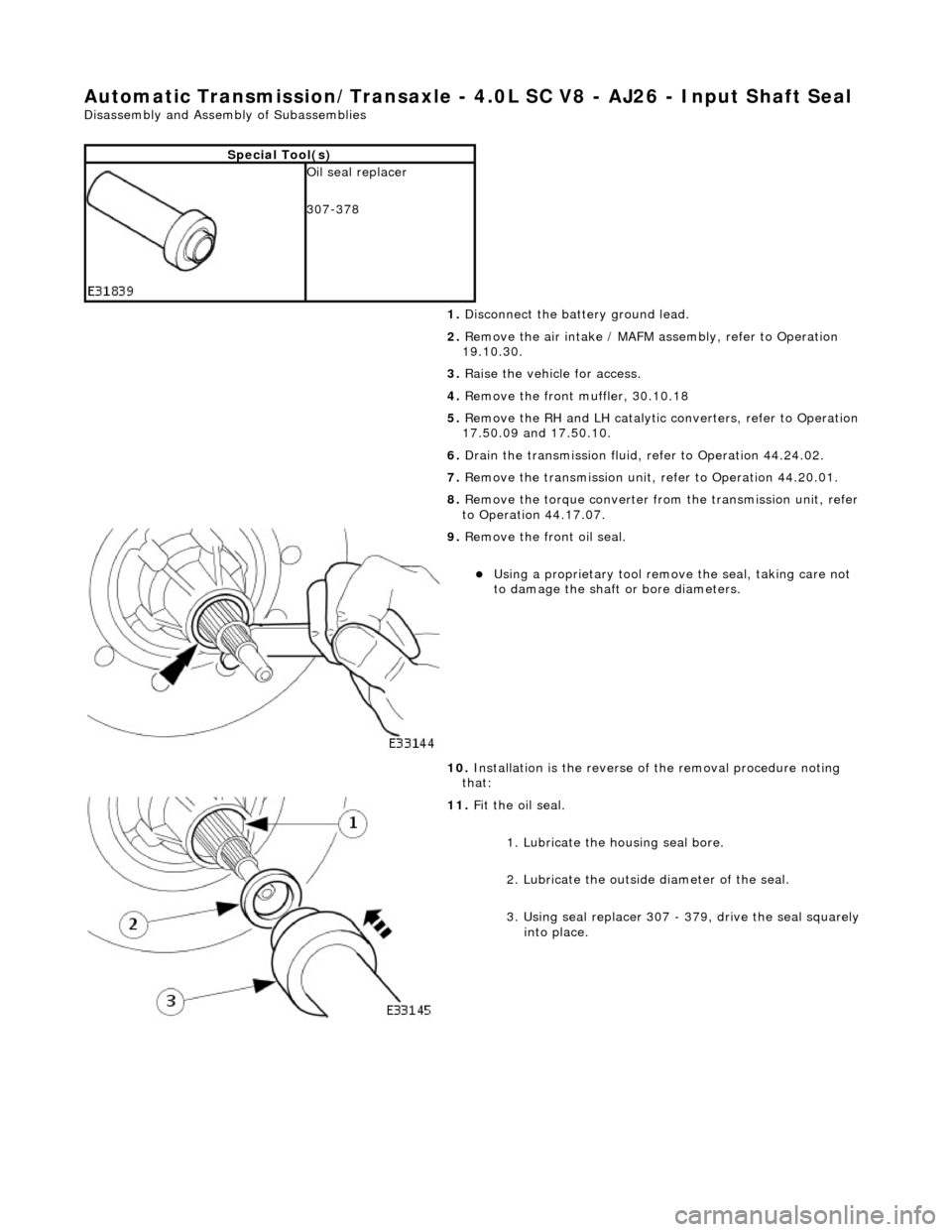
Automatic Transmission/Transaxle - 4.0L SC V8 - AJ26 - Input Shaft Seal
Disassembly and Assembly of Subassemblies
Special Tool(s)
Oil seal replacer
307-378
1. Disconnect the battery ground lead.
2. Remove the air intake / MAFM assembly, refer to Operation
19.10.30.
3. Raise the vehicle for access.
4. Remove the front muffler, 30.10.18
5. Remove the RH and LH catalytic converters, refer to Operation
17.50.09 and 17.50.10.
6. Drain the transmission fluid, refer to Operation 44.24.02.
7. Remove the transmission unit, refer to Operation 44.20.01.
8. Remove the torque converter fro m the transmission unit, refer
to Operation 44.17.07.
9. Remove the front oil seal.
Using a proprietary tool remove the seal, taking care not
to damage the shaft or bore diameters.
10. Installation is the reverse of the removal procedure noting
that:
11. Fit the oil seal.
1. Lubricate the housing seal bore.
2. Lubricate the outside diameter of the seal.
3. Using seal replacer 307 - 379, drive the seal squarely into place.
Page 1457 of 2490

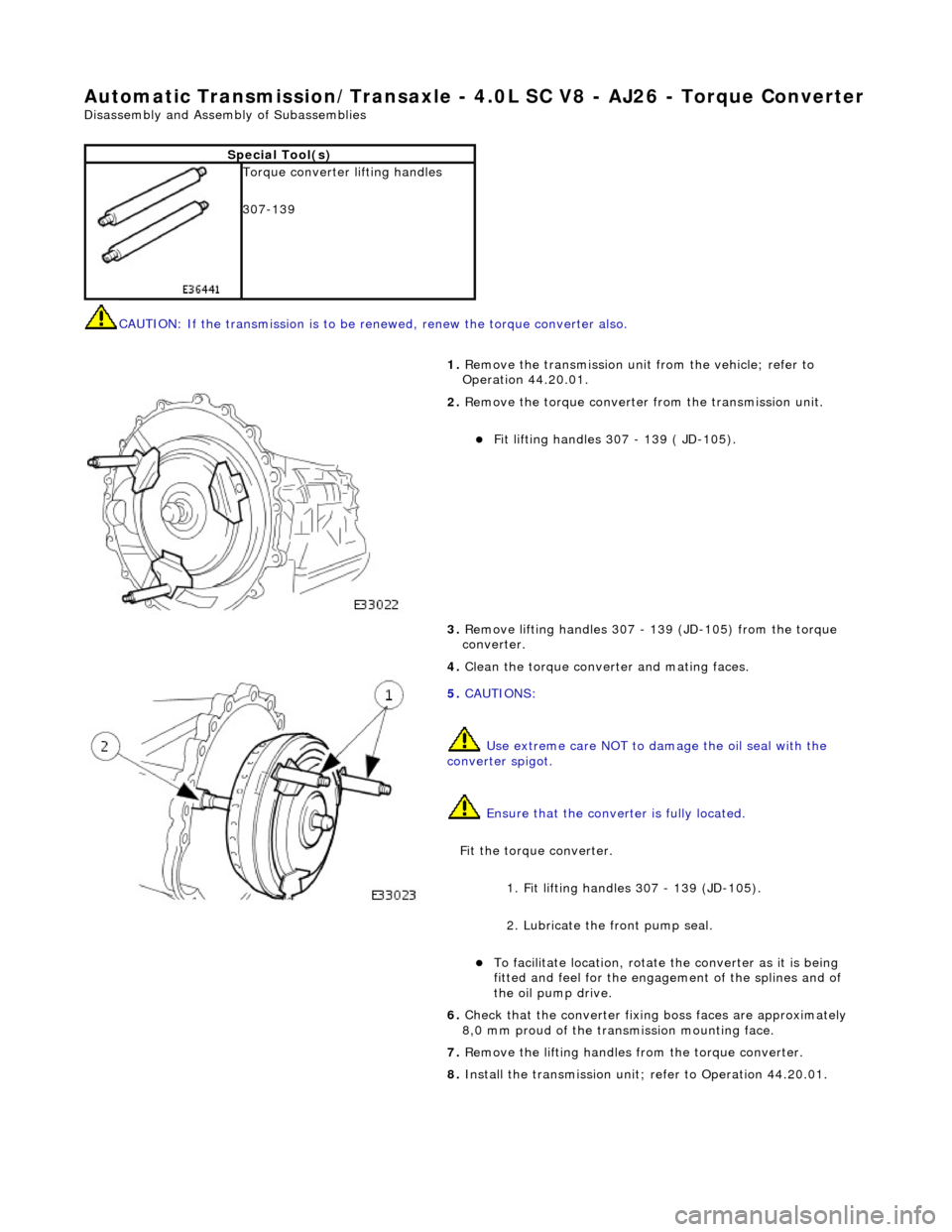
Automatic Transmission/Transaxle - 4.0L SC V8 - AJ26 - Torque Converter
Disassembly and Assembly of Subassemblies
CAUTION: If the transmission is to be renewed, renew the to rque converter also.
Special Tool(s)
Torque converter lifting handles
307-139
1. Remove the transmission unit from the vehicle; refer to
Operation 44.20.01.
2. Remove the torque converter from the transmission unit.
Fit lifting handles 307 - 139 ( JD-105).
3. Remove lifting handles 307 - 139 (JD-105) from the torque
converter.
4. Clean the torque conver ter and mating faces.
5. CAUTIONS:
Use extreme care NOT to damage the oil seal with the
converter spigot.
Ensure that the conver ter is fully located.
Fit the torque converter.
1. Fit lifting handles 307 - 139 (JD-105).
2. Lubricate the front pump seal.
To facilitate location, rotate the converter as it is being
fitted and feel for the engage ment of the splines and of
the oil pump drive.
6. Check that the converter fixing boss faces are approximately
8,0 mm proud of the transm ission mounting face.
7. Remove the lifting handles from the torque converter.
8. Install the transmission unit; refer to Operation 44.20.01.
Page 1459 of 2490
6. Fit the mounting bracket for th e front muffler. Tighten the two
bolts to the specified torque figure.
7. Secure the transmission to the engine.
Loosely assemble - Cooler pipe clip bolt.
Loosely assemble - Ground lead bolt.
Loosely assemble - Starter cable clips, two bolts.
Loosely assemble - Catalyst bracket bolts, two each side.
Loosely assemble - Rema ining eight bolts.
Refer to the illustration - tighten in sequence 1,2,3,4 then
in any order.
8. Secure the torque converter to the engine.
1. Fit, but do not tighten, the three bolts which secure the torque converter to the drive plate.
Prevent crankshaft rotation and tighten ALL converter
bolts to the specified torque figure.
2. Fit the blanking plug to the cylinder block access aperture.
9. Secure the oil cooler pipes.
Fit new Dowty washers to each union. Connect the upper
and lower cooler pipes.
Tighten to the specified torque figure.
Page 1462 of 2490
Transmission/Transaxle Cooling - 4.0L NA V8 - AJ27/3.2L NA V8 - AJ26 -
Transmission Cooling
Description and Operation
The transmission fluid cooling system maintains fluid temperature within specified limits.
Parts List
Component Descriptions
The transmission fluid pipes:
Transfer fluid from the transmission to the cooler under the action of the hydraulic system pump. Return the cooled fluid from th e cooler to the transmission.
The transmission fluid cooler:
Is a plate type made from aluminum. Is mounted in the engi ne cooling radiator right-hand end tank.
Overheating Protection
If the engine coolant or transm ission fluid temperatures exceed their predefined limits, th e transmission control module locks
the torque converter clutch. By reducing slip, this minimises th e amount of heat transferred to the engine cooling system from
the transmission fluid.
ItemPart NumberDescription
1—Fluid pipe, oil FROM cooler
2—Fluid pipe, oil TO cooler