Page 1808 of 2490

Air Conditioning - Condenser Core
Removal and Installation
Removal
1. Disconnect battery ground cable (IMPORTANT, see SRO
86.15.19 for further information).
2. Drain radiator coolant only; refer to 26.10.01 or (SC)
26.10.01.
3. Recover refrigerant from air co nditioning system; refer to
82.30.30.
4. Release both gas struts, set the engine cover fully forward to
the service access position an d support with a wooden (or
similar) strut.
5. CAUTION: Take care not to damage hood or radiator
grille.
Remove twin fan and motor as sembly; refer to 26.25.12.
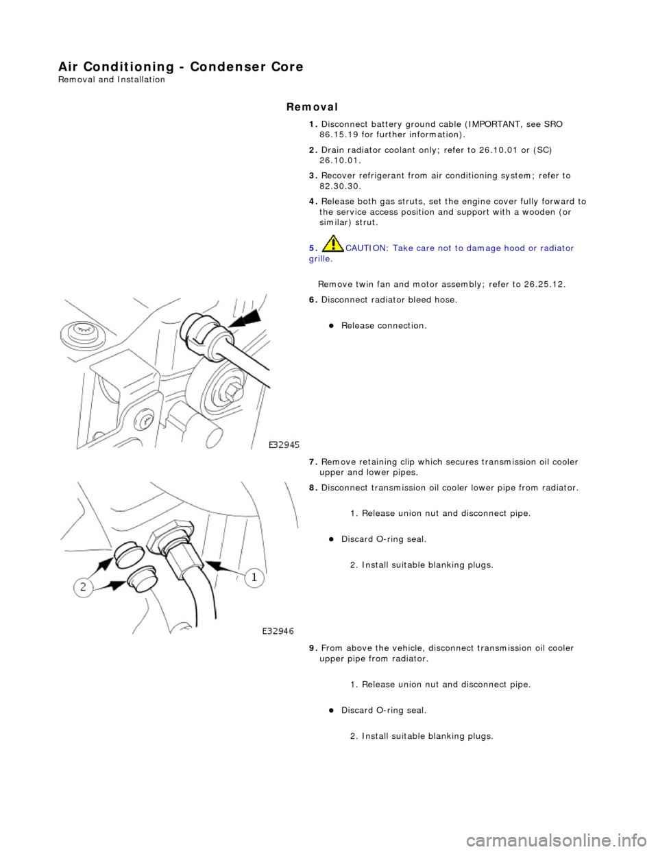
6. Disconnect radiator bleed hose.
Release connection.
7. Remove retaining clip which secures transmission oil cooler
upper and lower pipes.
8. Disconnect transmission oil cooler lower pipe from radiator.
1. Release union nut and disconne ct pipe.
Discard O-ring seal.
2. Install suitable blanking plugs.
9. From above the vehicle, discon nect transmission oil cooler
upper pipe from radiator.
1. Release union nut and disconne ct pipe.
Discard O-ring seal.
2. Install suitable blanking plugs.
Page 1812 of 2490
2. If previously removed, install condenser to receiver / drier line
at condenser.
Remove blanking plugs.
Install new O-ring seal and lubricate with clean
compressor oil.
Install bolt (8-10 Nm).
Locate hose to clip.
3. Install condenser to radiator.
Install bolts (8-10 Nm).
4. Install radiator / condenser assembly.
5. Connect condenser to receiver / dr ier line at receiver / drier.
Remove blanking plugs.
Install new O-ring seal and lubricate with clean A/C
compressor oil.
Page 1813 of 2490
Connect hose.
Install bolt (8-10 Nm).
6. Connect compressor to condenser discharge line at condenser.
Remove blanking plugs.
Install new O-ring seal an d lubricate with clean A/C
compressor oil.
Connect hose.
Install bolt (8-10 Nm).
7. Connect transmission o il cooler upper pipe.
Remove blanking plugs.
Install new O-ring seal and lu bricate with clean automatic
transmission fluid.
Connect union nut to radiator and tighten.
8. Connect transmission oil cooler lower pipe.
Remove blanking plugs.
Install new O-ring seal and lu bricate with clean automatic
transmission fluid.
9. Connect radiator blee d hose to radiator.
Page 1818 of 2490
Air Conditioning - Pressure Cutoff Switch
Removal and Installation
Removal
Installation
1. Remove pressure switch.
Disconnect connector.
• NOTE: Discard O-ring seal.
Remove switch.
1. NOTE: Clean mating faces, instal l new O-ring seal and lubricate with clean compressor oil.
Installation is a reversal of the removal procedure.
Page 1819 of 2490
Air Conditioning - Receiver Drier
Removal and Installation
Removal
Installation
1. Disconnect battery ground cable (IMPORTANT, see SRO
86.15.19 for further information).
2. Remove air cleaner assemb ly; refer to 19.10.05.
3. Recover refrigerant from air co nditioning system; refer to
82.30.30.
4. Disconnect receiver / drier to evaporator line from receiver /
drier bottle.
Remove bolt.
Disconnect hose and discard O-ring seal.
Install suitable blanking plugs.
5. Disconnect condenser to receiver / drier line from receiver /
drier bottle.
Remove bolt.
Disconnect hose and discard O-ring seal.
Install suitable blanking plugs.
6. Remove drier bottle assembly.
Remove bolts.
Remove assembly.
Remove mounting rubbers.
1. NOTE: Install new O-ring seals and lubricate with clean
compressor oil.
Installation is reverse of removal procedure.
2. Tighten fixings to specification (8-10 Nm).
Page 1837 of 2490

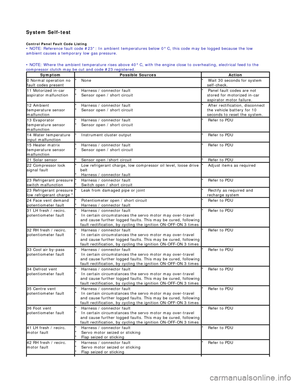
System Self-test
Control Panel Fault Code Listing • NOTE: Reference fault code #23*: In ambient temperatures below 0° C, this code may be logged because the low
ambient causes a tempor ary low gas pressure.
• NOTE: Where the ambient temperature rises above 40° C, with the engine close to overheating, electrical feed to the
compressor clutch may be cut and code #23 registered.
SymptomPossible SourcesAction
0 Normal operation no
fault codes presentNone
*Wait 30 seconds for system
self-check.
*
11 Motorized in-car
aspirator malfunctionHarness / connector fault
Sensor open / short circuit
*
*Panel fault codes are not
stored for motorized in-car
aspirator motor failure.
*
12 Ambient
temperature sensor
malfunctionHarness / connector fault
Sensor open / short circuit
*
*After rectification, disconnect
the vehicle battery for 10
seconds to reset the system.
*
13 Evaporator
temperature sensor
malfunctionHarness / connector fault
Sensor open / short circuit
*
*Refer to PDU
*
14 Water temperature
input malfunctionInstrument cl uster output
*Refer to PDU
*
15 Heater matrix
temperature sensor
malfunctionHarness / connector fault
Sensor open / short circuit
*
*Refer to PDU
*
21 Solar sensorSensor open /short circuit
*Refer to PDU
*
22 Compressor lock
signal faultLow refrigerant charge, low compressor oil level, loose drive
belt Harness / connector fault
*
*Adjust items as required
*
23 Refrigerant pressure
switch malfunctionHarness / connector fault
Switch open / short circuit
*
*Refer to PDU
*
23 Refrigerant pressure
low refrigerant charge * Leak from damaged pipe or joint
*Rectify as required and
recharge system
*
24 Face vent demand
potentiometer faultPotentiometer open / short circuit
Harness / connector fault
*
*Refer to PDU
*
31 LH fresh / recirc.
potentiometer faultHarness / connector fault
In certain circumstances the servo motor may over-travel
and cause further logged faults. This may be cured, following
fault rectification, by cycling the ignition ON-OFF-ON 3 times
*
*Refer to PDU
*
32 RH fresh / recirc.
potentiometer faultHarness / connector fault
In certain circumstances the servo motor may over-travel
and cause further logged faults. This may be cured, following
fault rectification, by cycling the ignition ON-OFF-ON 3 times
*
*Refer to PDU
*
33 Cool air by-pass
potentiometer faultHarness / connector fault
In certain circumstances the servo motor may over-travel
and cause further logged faults. This may be cured, following
fault rectification, by cycling the ignition ON-OFF-ON 3 times
*
*Refer to PDU
*
34 Defrost vent
potentiometer faultHarness / connector fault
In certain circumstances the servo motor may over-travel
and cause further logged faults. This may be cured, following
fault rectification, by cycling the ignition ON-OFF-ON 3 times
*
*Refer to PDU
*
35 Centre vent
potentiometer faultHarness / connector fault
In certain circumstances the servo motor may over-travel
and cause further logged faults. This may be cured, following
fault rectification, by cycling the ignition ON-OFF-ON 3 times
*
*Refer to PDU
*
36 Foot vent
potentiometer faultHarness / connector fault
In certain circumstances the servo motor may over-travel
and cause further logged faults. This may be cured, following
fault rectification, by cycling the ignition ON-OFF-ON 3 times
*
*Refer to PDU
*
41 LH fresh / recirc.
motor faultHarness / connector fault
Servo motor seized or sticking
Flap seized or sticking
*
*
*Refer to PDU
*
42 RH fresh / recirc.
motor faultHarness / connector fault
Servo motor seized or sticking
Flap seized or sticking
*
*
*Refer to PDU
*
Page 1854 of 2490
Instrument Cluster - Instrument Cluster
Description and Operation
ItemDescription
1Variable Power Steering
2Coolant Level
3Fuel Level
4Oil Pressure
5Lamp Dimmer
6Driver's Switchpack
7Generator (Charge Warning Lamp)
8Catalyst Overheat
9Instrument Cluster
10Climate Control (Signal to Module)
11ICE Head Unit
Page 1859 of 2490
Horn - Horn
Description and Operation
The horns, located behind the radiator gril le, each side of the radiator, are controlled by the Body Processor Module (BPM),
as described below.
The switch, located on the steering wheel pad, is operated, it signals the BPM to sound the horn. The BPM responds by
providing an earth from the horn-output to the horn relay coil. The relay contacts are subsequently closed and the horns
sound.
The horn operating relay, R6 is located in the engine compartm ent fusebox at the left hand side of the engine compartment.