Page 1270 of 2490

1.1. The hydraulic system has 'fail-safe' characteristics regardin g its electrical operation, such that should the power
supply be lost to the electro-hydraulic actuators the transmission will initiate a limp-home mode.
2. 2. Recognition of critical shift operation by monitoring the last element in the signal path, ie the solenoid valve, and
checking by means of redundant me asured variables, ie engine speed, input speed and output speed.
3. 3. Each time the vehicle is started there is a check on the entire safety hardware and the associated program parts
and signal paths. A malfunction in this part of the system, or triggering of the safety circuit, is communicated to
the operator through the illumination of the transmission warning lamp.
TCM Inputs
Input Speed Sensor (Torque Converter Turbine)
The input speed sensor provides the TCM with transmission inpu t shaft speed information. This signal is produced from an
inductive pick-up, generating 30 pulses per revolution.
Transmission Output Speed Sensor
The output speed sensor provides the TCM with transmission ou tput shaft speed information. This signal is produced from
an inductive pick-up, generati ng 36 pulses per revolution.
Transmission Oil Temperature Sensor
A thermistor which provides an electrical indication of the oi l temperature to the TCM. The signal is measured as a voltage
with reference to analog ue ground in the TCM.
Kickdown Switch (where fitted)
Kickdown is intended to provide maximum vehicle acceleration , via the appropriate downshift(s), when the operator uses
full throttle. A kickdown switch provides an electrical signal to the TCM wh en the accelerator pedal is fully pressed. The
switch is normally open, connected to vehicle ground. Should the switch fail the TCM will detect kickdown using the
accelerator pedal position.
Throttle Pedal Stop (where fitted)
This component, used where the kickdown switch is not fitted, limits throttle pedal travel .in the same way. The kickdown
feature is retained, but is controlled by throttle position only. The pedal stop must be set, using the PDU, in the same way
as the kickdown switch to optimize performance.
Mode Selection Switch
The mode selection switch is a two position switch indicati ng to the TCM the current performance mode selected by the
driver. The switch generates a tw o-bit digital input to the TCM.
Rotary Position Switch
The rotary position switch detects the position of the transmis sion selector shaft. The switch is supplied as part of a new
transmission assembly, mounted on the transmission body. The swit ch is used to indicate to the TCM the six positions of the shaft: Park, Reverse, Neutral, Drive, Third and Second. The switch provides a four-bit input to the TCM.
Drive to Fourth Switch
Detects the movement of the selector lever from Drive to Fourth position. The selector cable, and therefore the transmission selector shaft, does not move as the lever is operated between these two positions. The switch is located within the 'J-gate'
assembly, producing a digital output to indicate to the TCM that the lever has moved from D to 4 .
Serial Communications Interfaces
Page 1271 of 2490

Controller Area Network (CAN)
The TCM is an integral part of the CAN system which facilitates the interchange of real-time data between control modules
and sensors. Please see section 303- 14 for a full description of CAN.
OBDII Interface
Data concerning OBDII related transmission failures is stored in the ECM for access via the J1962 socket.
System Functions
Range Selection
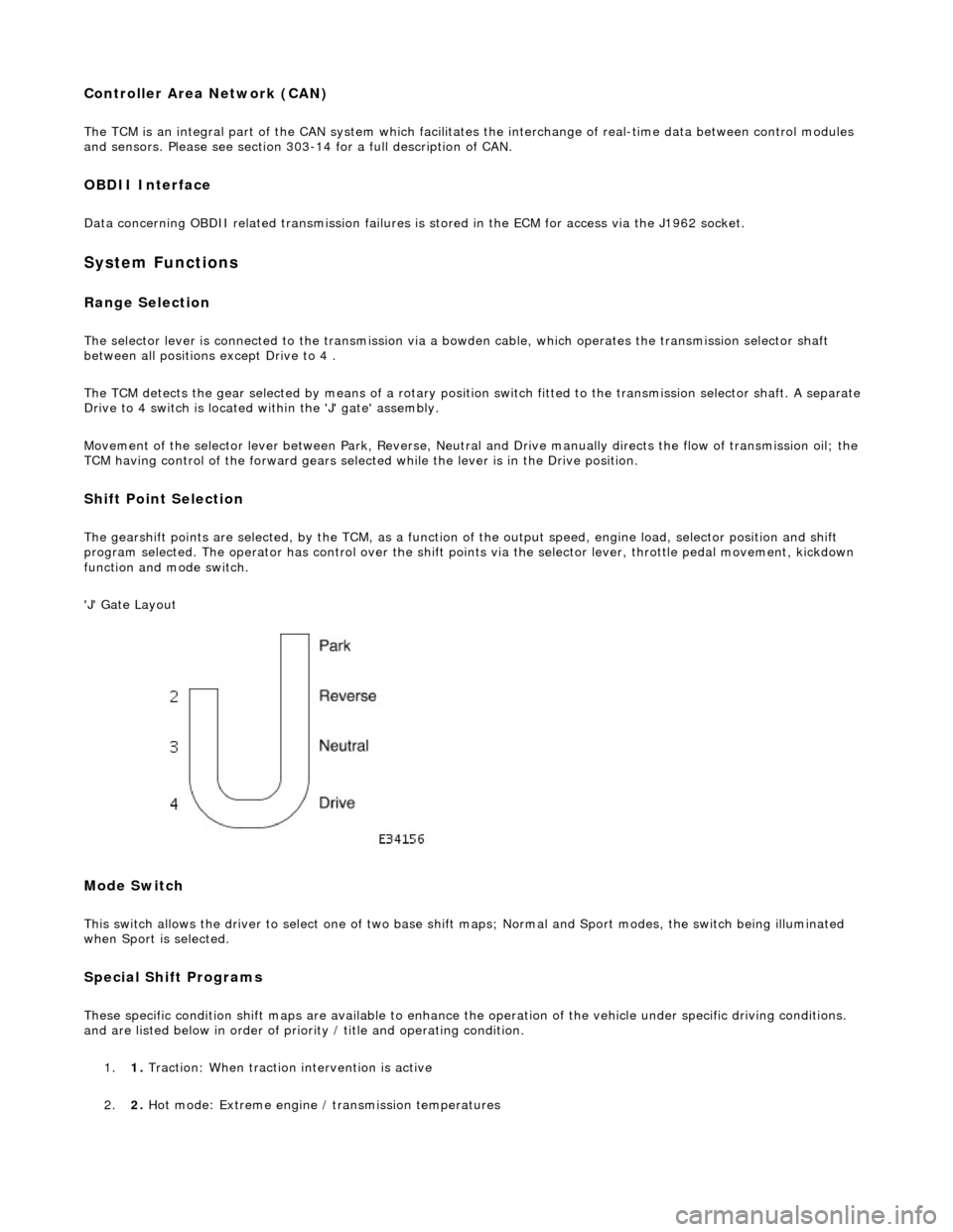
The selector lever is connected to the transmission via a bowden cable, which operates the transmission selector shaft
between all positions except Drive to 4 .
The TCM detects the gear selected by means of a rotary position switch fitted to the transmission selector shaft. A separate
Drive to 4 switch is located within the 'J' gate' assembly.
Movement of the selector lever between Park, Reverse, Neutral and Drive manually directs th e flow of transmission oil; the
TCM having control of the forward gears selected while the lever is in the Drive position.
Shift Point Selection
The gearshift points are selected, by the TCM, as a function of the output speed, engine load, selector position and shift
program selected. The operator has control over the shift points via the selector lever, throttle pedal movement, kickdown
function and mode switch.
'J' Gate Layout
Mode Switch
This switch allows the driver to select one of two base shift maps; Normal and Sport modes, the switch being illuminated
when Sport is selected.
Special Shift Programs
These specific condition shift maps are available to enhance the operation of the vehicle under specific driving conditions.
and are listed below in order of priority / title and operating condition.
1. 1. Traction: When traction intervention is active
2. 2. Hot mode: Extreme engine / transmission temperatures
Page 1279 of 2490
Connect the scan tool 1
Have the DTC(s) and freeze frame data been recorded?
Yes GO to B2
B2: CHECK PRESSURE REGULATOR COIL CONTINUITY
With, EM007 disconnected, measure the resistance between
EM007/052 and EM007/004 1
Is the resistance >5.0 and <7.0 OHM?
Yes
GO to B6
No GO to B3
B3: CHECK HARNESS SIGNAL CONTINUITY
Page 1308 of 2490
With EM007 and EM046 disconnected, measure the
resistance between EM046/010 and EM007/044 1
Is the resistance < 0.5 OHM?
Yes GO to E4
No Inspect harness / connectors EM007 and EM046 for damage,
corrosion, bent / pushed back pins. Repair as necessary and
test the system for normal operation.
E4: CHECK OUTPUT SPEED SENSOR COIL CONTINUITY
Page 1313 of 2490
With EM007 and EM046 disconnected, measure the
resistance between EM046/014 and EM007/006 1
Is the resistance < 0.5 OHM?
Yes GO to F4
No Inspect harness / connectors EM007 and EM046 for damage,
corrosion, bent / pushed back pins. Repair as necessary and
test the system for normal operation.
F4: CHECK INPUT SPEED SENSOR COIL CONTINUITY
Page 1318 of 2490
With EM007 and EM046 disconnected, measure the
resistance between EM046/010 and EM007/044 1
Is the resistance < 0.5 OHM?
Yes GO to G4
No Inspect harness / connectors EM007 and EM046 for damage,
corrosion, bent / pushed back pins. Repair as necessary and
test the system for normal operation.
G4: CHECK OUTPUT SPEED SENSOR COIL CONTINUITY
Page 1323 of 2490
With EM007 and EM046 disconnected, measure the resistance between EM046/014 and EM007/006 1
Is the resistance < 0.5 OHM?
Yes GO to I4
No Inspect harness / connectors EM007 and EM046 for damage,
corrosion, bent / pushed back pins. Repair as necessary and
test the system for normal operation.
I4: CHECK INPUT SPEED SENSOR COIL CONTINUITY
Page 1326 of 2490
With EM007 and EM046 disconnected, measure the resistance between EM046/010 and EM007/044 1
Is the resistance < 0.5 OHM?
Yes GO to I7
No Inspect EM007 and EM046 for corrosion, bent / pushed back
pins or locate and repair th e harness Test the system for
normal operation
I7: CHECK OUTPUT SPEED SENSOR COIL CONTINUITY