Page 510 of 2490
The lower steeri ng col
umn:
Is a han
ded assembly
.
Incorporates
a col
umn to toeboard seal
which comprises a rolling element having two, low friction, PTFE rings. The
rolling element locates in a rubber b oot which seals to the toeboard.
Has a lowe
r universal joint connecting the
lower column to the steering rack.
Has an upper un
iversal joint connecting
the lower column to the upper column.
Has a NVH damper in
corporated into
the upper universal joint assembly.
May be installed in an
y orientation on the universal joint splines.
R
e
quires no setting or adjustment.
Has no s
e
rviceable components.
It is essential to disconnect the lower column from the steer ing rack before removing the engine or front suspension
crossbeam.
It e
m
Par
t
Number
De
scr
iption
1-Boot
2-Uni
v
ersal joint to upper column
3-Lower steeri
ng col
umn shaft
4-R
e
taining bolts
5-Uni
v
ersal joint to steering rack
Lower Steering Column
Page 516 of 2490
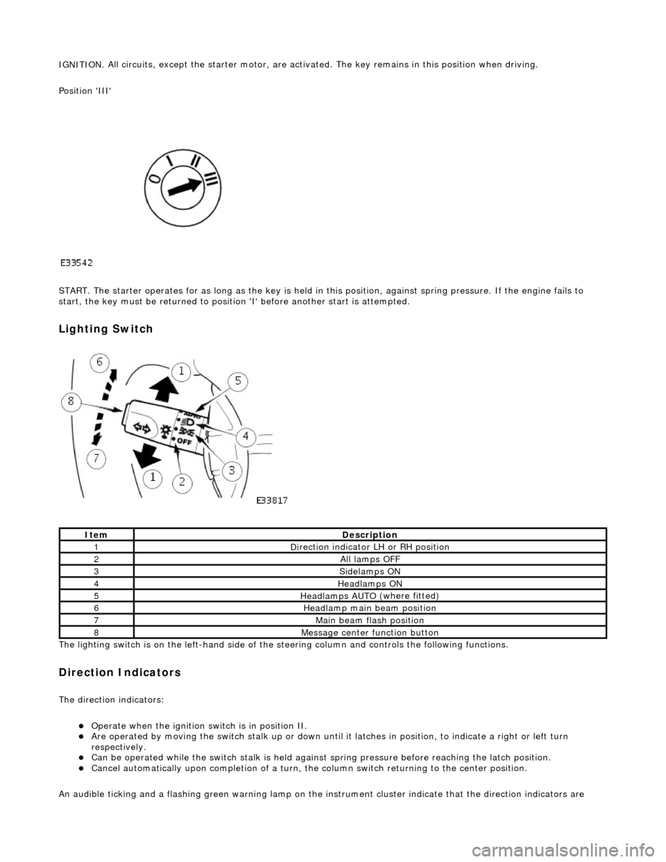
IGNITION.
All circuits, except the star
ter motor, are activated. The key rema ins in this position when driving.
Position 'III'
START. The starter operates for as long as the key is held in this position, ag ainst spring pressure. If the engine fails to
start, the key must be returned to position 'I' befo re another start is attempted.
Lighting Switch
The li
ghting switch is on the left-h
and side of the steering column and controls the following functions.
Direction Indicators
The direction in
dicators:
Operate
when the ignition switch is in position II.
Are operat
ed by movi
ng the switch stalk up or down until it latches in position, to in
dicate a right or left turn
respectively.
Can be o p
erated while the switch stalk is held against
spring pressure before reaching the latch position.
Cancel
automatically upon completion of a turn, the
column switch returning to the center position.
An audible ticking and a flashing green warning lamp on the in strument cluster indicate that the direction indicators are
Ite
m
De
scr
iption
1D
i
rection indicator LH or RH position
2All lamps OFF
3Side
lamps ON
4Headlamps ON
5Headlamps AUT O
(where fitted)
6He
adlam
p main beam position
7Mai
n
beam flash position
8M
e
ssage center function button
Page 517 of 2490
o
perating. If an indicator bulb fails, the warning
lamp and ticking operate at twice the normal rate.
Sidelam
ps and Headlamps
Thes
e are controlled by rotating the end of the column switch as follows.
In the OFF position:
All
exterior lamps are switched OFF.
In the sidelamp position:
The front
sidelamps, tail, license plate and any other la
mps required by local legislation are switched ON.
The
sidelamps tell-tale lamp illuminates.
In the headlamp position, with the ignition switch in position II:
The h
eadlamps are switched ON in addition to the lamps switched on in the sidelamp position.
If the ignition is switched to the OFF position with the column switch in the headlamp position, the sidelamps, tail and
license plate lamps will stay ON, but the headlamps will switch OFF.
In the AUTO position (where fitted), with the ignition switch in position II:
Th
e sensor mounted on the back of the interior rear view
mirror monitors exterior light levels and automatically
switches the sidelamps and di pped headlamps ON and OFF.
The sensitivity level can be adjusted by turn ing the sensor control knob on the back of the interior mirror, left to decrease or
right to increase. The sensor must not be covered and the windscreen must be kept clean.
Headlamp Main Bea
m Position
Wi
th the column switch in
the headlamp position:
Movin
g the switch stalk away fro
m the steering wheel switches the headlamps to main beam.
Movin
g the switch stalk towards the steering wheel switches the headlamps to dipped beam.
The main beam tell-tale lamp illuminates when the headlamps are switched to main beam.
Ma
in Beam Flash
Wi
th the ignition switch and column switch in any position:
Pulling the
switch stalk agains
t spring pressure towards th e steering wheel illuminates the headlamps on main beam
for as long as the switch is held.
The main beam tell-tale lamp illuminates while the headlamps are illuminated.
M
essage Center Functions
T
he message center functions:
Are se
lected by the button located at the end of the lighting switch stalk.
Are se
lected in turn, by repeatedly pressing the button,
from the odometer reading, through the trip computer data
in sequence, and back to th e odometer reading again.
Page 1377 of 2490
16. Remove the engine rear mounting bracket.
1. Remove the engine rear mounting to bracket bolt.
2. Remove the mounting bracket to body bolts.
17. Detach the driveshaft from th e transmission drive flange.
If the transmission is to be refitted, mark the position of
the coupling to drive flange.
17. CAUTION: Under no circ umstances remove the
driveshaft to flexible coupling fixings.
Remove the transmission drive flange to flexible coupling
three fixings.
18. Lower the transmission unit by carefully releasing the engine
support beam and by loweri ng the transmission jack.
19. Detach the gear selector cable from the transmission unit.
1. Remove the selector cable ball pin to selector lever nut.
2. Remove the selector cable to transmission casing bolts.
20. Disconnect the transmission harness multiplug.
1. Rotate the locking lever to release.
2. Disconnect the multiplug.
Page 1386 of 2490
13. Refit the rotary switch and tighten the two screws to the
specified torque figure. Locate the switch harness into the clips.
14. Connect the fluid cooler pipes to the transmission.
Remove the blanking plugs.
Fit new O-ring seals.
Tighten the union nuts to the specified torque figure.
15. Remove the engine support beam.
Remove both engine lifting brackets 303 - 536.
16. Refit the RH downpipe catalytic converter. Refer to Operation
17.50.09 and 17.50.10
17. Refit the front muffler. Refer to Operation 30.10.18.
18. Refit the LH downpipe catalytic converter. Refer to Operation
17.50.09
19. Lower the vehicle on the ramp.
Page 1855 of 2490
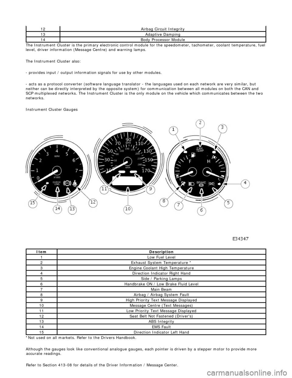
The In
strument Cluster is the primary electronic control module for the speedomete
r, tachometer, coolant temperature, fuel
level, driver information (Message Centre) and warning lamps.
The Instrument Cluster also:
- provides input / output informatio n signals for use by other modules.
- acts as a protocol converter (software language translator - the languages used on each network are very similar, but
neither can be directly interp reted by the opposite system) for communication between all modules on both the CAN and
SCP multiplexed networks. The Instrument Cluster is the only module on the vehicle which communicates between the two
networks.
Instrument Cluster Gauges
*Not used on all markets. Refer to the Drivers Handbook.
Although the gauges look like conventional analogue gauges, each pointer is driven by a stepper motor to provide more
12Ai
rbag Circuit Integrity
13Adaptive Damping
14Body Processor
Module
It
em
De
scription
1Low Fu
el Level
2Exhaus
t System Temperature *
3E
ngine Coolant High Temperature
4Di
rection Indicator Right Hand
5Side
/ Parking Lamps
6Handbrake ON / Low
Bra
ke Fluid Level
7Main
Beam
8Ai
rbag / Airbag System Fault
9Hi
gh Priority Text
Message Displayed
10M
essage Centre (Text Messages)
11Low Pri
ority Text Message Displayed
12Se
at Belt Not Fa
stened (Driver's)
13ABS Integrity
14EMS Fault
15D
irection Indicator Left Hand
accu
rate readings.
Refer to Section 413-08 for details of the Driver Information / Message Center.
Page 1919 of 2490
Exterior Lighting - Exterior Lighting
Description and Operation
A multi-function switch located on the left stalk of the steering column switch assembly permits selection of either parking
(side), headlamps, auto-headlamp or off. Selection of a particular mode provides the appropriate input to the body
processor module (BPM).
Where the auto headlamp function is incorporated, a light sensor in the interior rear view mirror monitors ambient light and
provides an input to the BPM. The BPM responds by switching the low beam headlamps on or off as appropriate for the
prevailing light conditions.
The front and rear fog lamp switch is located on the fascia outboard of the steering column.
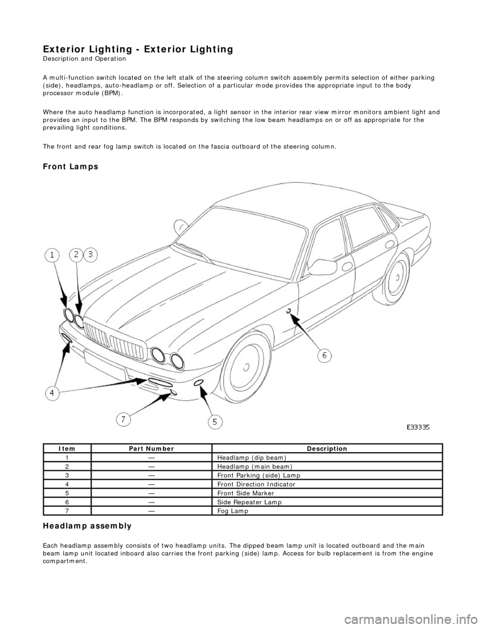
Front Lamps
Headlamp assembly
Each headlamp assembly consists of tw o headlamp units. The dipped beam lamp unit is located outboard and the main
beam lamp unit located inboard also carries the front parking (side) lamp. Access for bulb replacement is from the engine
compartment.
ItemPart NumberDescription
1—Headlamp (dip beam)
2—Headlamp (main beam)
3—Front Parking (side) Lamp
4—Front Direction Indicator
5—Front Side Marker
6—Side Repeater Lamp
7—Fog Lamp
Page 1920 of 2490
Direction indicator and side marker lamps
Each front direction indicator and side marker lamp is retained in the bumper cover by a lug at one end and a spring clip at
the other end. The side marker lamps are not electrically connected for certain markets.
The side repeater lamps are secured by sp ring clips on the lower edge of the lamp unit. In certain markets Jaguar leaper
badges are substituted for side repeater lamps.
Fog lamps
The fog lamps are located in recesses in the front bump er and secured by three screws. The la mps which are not
interchangeable left to right, are accessed from the rear of the bumper.
Operation
All lamps are controlled by the BPM which provides an appropriate output in response to an input received when a selected
switch is operated.
All lamps receive an input direct from th e BPM with the exception of the main be am, dip beam and front fog lamps which
receive an input from the BPM vi a the respective relays and fuses; refer to section 418-01.
Fault analysis must be undertaken using the PDU. Refer to Diagnosis and Testing.
Consult the relevant Electrical Guid e for details of circuit operation.
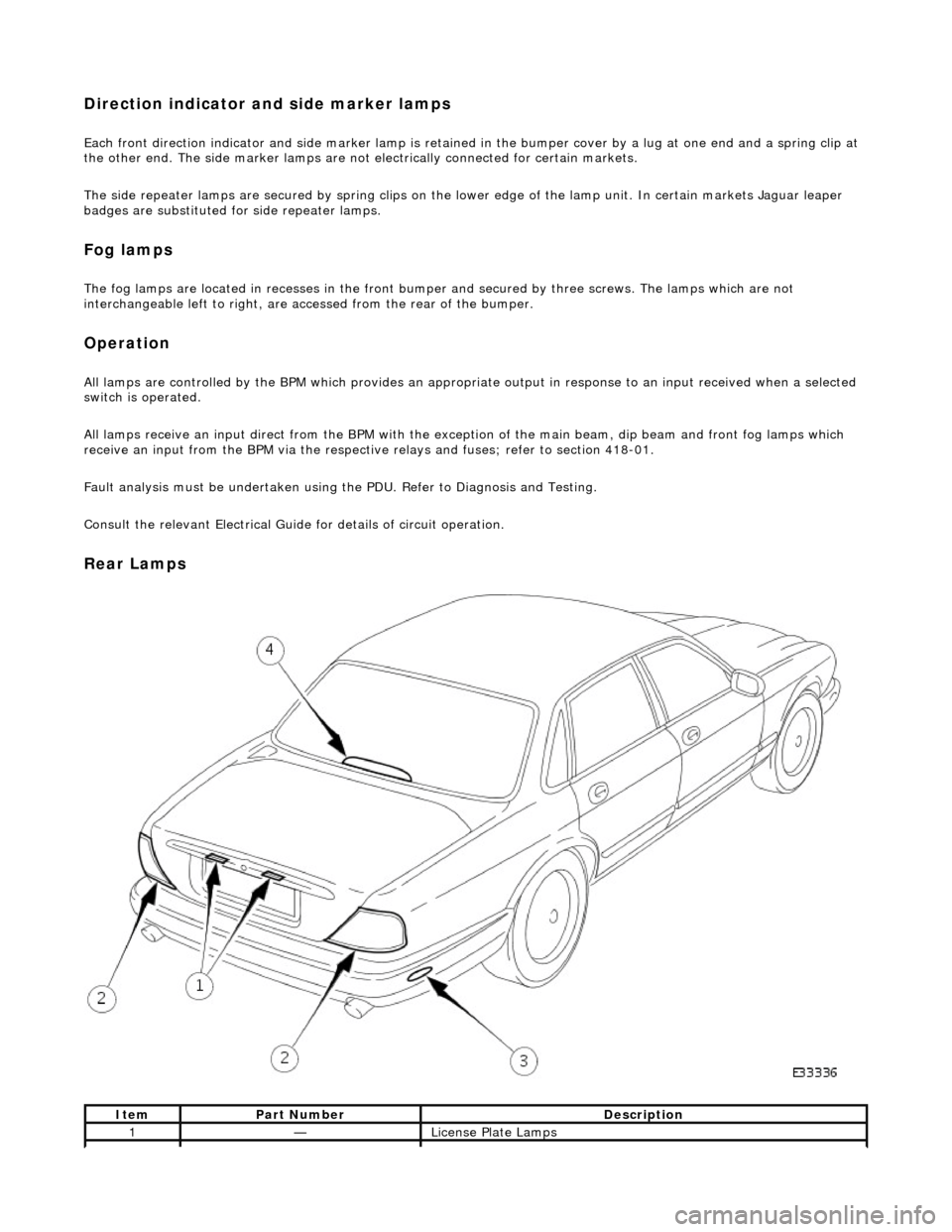
Rear Lamps
ItemPart NumberDescription
1—License Plate Lamps