1998 JAGUAR X308 fuel line
[x] Cancel search: fuel linePage 1083 of 2490
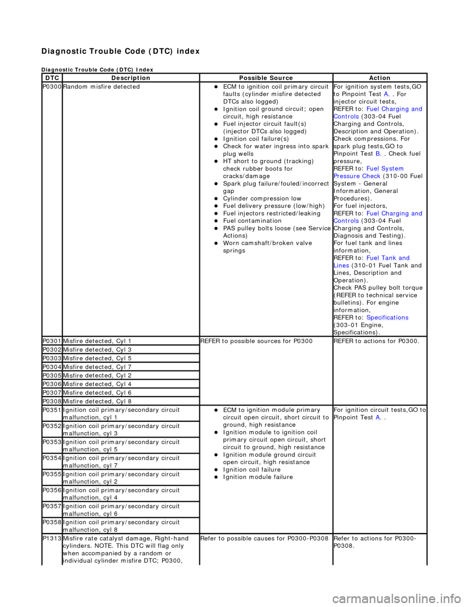
Diagnostic Trouble Code (D
TC) index
D
iagnostic Trouble Code (DTC) Index
DT
C
De
scription
Possib
le Source
Acti
on
P0300Ran
dom misfire detected
ECM t
o ignition coil primary circuit
faults (cylinder misfire detected
DTCs also logged)
Ignition coil
ground circuit; open
circuit, high resistance
F
uel injector circuit fault(s)
(injector DTCs also logged)
Ignition coil
failure(s)
Check f
or water ingress into spark
plug wells
HT sho
rt to ground (tracking)
check rubber boots for
cracks/damage
Spark plug
failure/fouled/incorrect
gap
Cy
linder compression low
F
uel delivery pressure (low/high)
F
uel injectors restricted/leaking
Fuel contamination
P
AS pulley bolts loose (see Service
Actions)
W
orn camshaft/broken valve
springs
For ign
ition system tests,GO
to Pinpoint Test A.
. For
inje
ctor circuit tests,
REFER to: Fuel Charging and
Controls (30
3-04 Fuel
Charging and Controls,
Description and Operation).
Check compressions. For
spark plug tests,GO to
Pinpoint Test B.
.
Check fuel
pressure,
REFER to: Fuel System
Pressure Check (31
0-00 Fuel
System - General
Information, General
Procedures).
For fuel injectors,
REFER to: Fuel Charging and
Controls (30
3-04 Fuel
Charging and Controls,
Diagnosis and Testing).
For fuel tank and lines
information,
REFER to: Fuel Tank and
Lin
es
(310-01 Fuel Tank and
Lines, Description and
Operation).
Check PAS pulley bolt torque
(REFER to technical service
bulletins). For engine
information,
REFER to: Specifications
(3
03-01 Engine,
Specifications).
P0301Misfire
detected, Cyl 1
R
EFER to possible sources for P0300
R
EFER to actions for P0300.
P0302Misfire
detected, Cyl 3
P0303Misfire
detected, Cyl 5
P0304Misfire
detected, Cyl 7
P0305Misfire
detected, Cyl 2
P0306Misfire
detected, Cyl 4
P0307Misfire
detected, Cyl 6
P0308Misfire
detected, Cyl 8
P0351Igni
tion coil primary/secondary circuit
malfunction, cyl 1
ECM to
ignition module primary
circuit open circuit, short circuit to
ground, high resistance
Igni
tion module to ignition coil
primary circuit open circuit, short
circuit to ground, high resistance
Ignition modu
le ground circuit
open circuit, hi gh resistance
Ignition coil
failure
Ignition modul
e failure
F
or ignition circuit tests,GO to
Pinpoint Test A.
.
P0352Igni
tion coil primary/secondary circuit
malfunction, cyl 3
P0353Igni
tion coil primary/secondary circuit
malfunction, cyl 5
P0354Igni
tion coil primary/secondary circuit
malfunction, cyl 7
P0355Igni
tion coil primary/secondary circuit
malfunction, cyl 2
P0356Igni
tion coil primary/secondary circuit
malfunction, cyl 4
P0357Igni
tion coil primary/secondary circuit
malfunction, cyl 6
P0358Igni
tion coil primary/secondary circuit
malfunction, cyl 8
P1313Misfire rate
catalyst damage, Right-hand
cylinders. NOTE. This DTC will flag only
when accompanied by a random or
individual cylinder misfire DTC; P0300,
R
efer to possible causes for P0300-P0308
R
efer to actions for P0300-
P0308.
Page 1095 of 2490
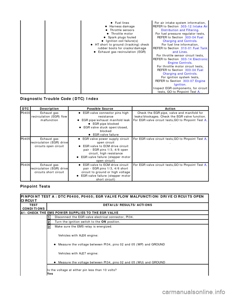
Diagnostic Trouble Code (D
TC) Index
Pinpoint Tests
Fue
l lines
Harness damage
Throttl
e sensors
Throttl
e motor
Spark plugs
fouled
Ignition coil
failure(s)
HT sho
rt to ground (tracking) check
rubber boots for cracks/damage
Exhaus
t gas recirculation (EGR)
F
or air intake syst
em information,
REFER to Section 303
-12
Intake Air
Distribu
tion and Filtering
.
F
or fuel pressure
regulator tests,
REF
ER to Section 303
-04
Fuel
Charging and Con
trols
.
F
or fuel line information,
REFER to Section 310
-01
Fuel Tank
and Lines.
F
or throttle sensor
circuit tests,
REFER to Section 303
-14
Electronic
Engine
Controls
.
Fo
r throttle motor
circuit tests,
REFER to Section 303
-04
Fuel
Charging and Con
trols
.
For ign
ition system tests,
REFER to Section 303
-07
Engine
Ignition.
Inspe
ct EGR components, for circuit
tests, GO to Pinpoint Test A.
.
DT
C
De
scription
Possib
le Source
Acti
on
P0400Exhaus
t gas
recirculation (EGR) flow malfunction
EGR
valve connector pins high
resistance
EGR pipe/exhaust manifold leak EGR pipe block
ed
EGR val
ve stuck open/closed,
blocked
EGR
valve failure
Check the EGR pi
pe, valve and manifold for
leaks/blockages. Check the EGR valve function.
For EGR valve circuit tests,GO to Pinpoint Test A.
.
P0405Exhaus
t gas
recirculation (EGR) drive
circuits open circuit
EGR valve power supply circuit o
pen circuit
EGR valve t
o ECM drive circuit
pair - EGR pins 1/3, 4/6 open circuit, high resistance
EGR val
ve failure (stepper motor
open circuit)
F
or EGR valve circuit tests,GO to Pinpoint Test
A.
.
P0406Exhaus
t gas
recirculation (EGR) drive
circuits short circuit
EGR valve t
o ECM drive circuit
pair - EGR pins 1/3, 4/6 short
circuit to ground or high voltage
EGR val
ve failure (stepper motor
short circuit)
F
or EGR valve circuit tests,GO to Pinpoint Test
A.
.
P
INPOINT TEST A : DTC P0400, P0405; EGR VALV
E FLOW MALFUNCTION/DRIVE CIRCUITS OPEN
CIRCUIT
TE
ST
CONDITIONS
D
ETAILS/RESULTS/ACTIONS
A1: CHECK
THE EMS POWER SU
PPLIES TO THE EGR VALVE
D
isconnect the EGR valve electrical connector, PI34.
1
Turn the ignition swi
tch to the ON
position.
2
Make sure the EMS re lay i
s energized.
Vehicles with AJ26 engine:
Me
asure the voltage between PI34, pins 02 and 05 (WP) and GROUND
Vehicles with AJ27 engine:
Me
asure the voltage between PI34, pins 02 and 05 (WU) and GROUND
3
Is th
e voltage at either pin less than 10 volts?
Yes
Page 1148 of 2490
Evaporative E
missions - Evaporative Emissions
Description an
d Operation
To reduce the emission of fuel vapour, th e fuel tank is vented to atmosphere through activated charcoal adsorption canister
(s) which collects the fuel droplets. The ch arcoal is periodically purged of fuel when the EVAP Canister Purge Valve opens
the vapour line between the canister(s) and the air intake induct ion elbow. This action allows manifold depression to draw
air through the canister atmospheric vent, taking up the deposited fuel from the charcoal adsorber and burning the resulting
fuel vapour in the engine.
The EVAP Canister Purge Valve is controlled by the engine management system ECM. Purging is carried out in accordance
with the engine management fu eling strategy (see below).
The fuel tank vapour outlet is via a removeable flange assemb ly on the top surface of the tank. The vapour storage canister
or canisters are fitted on the underside of the vehicle below the rear seats.
There are three variants of the evaporativ e system. All systems use the charcoal adsorber storage canisters and purge valve
and operate as described above. The specific features of each system are described below. The evaporative systems are
designated as :
sin g
le canister system
ru
nn
ing loss system
ru
nn
ing loss with On-board Re-fueling Vapour Recovery (ORVR) system
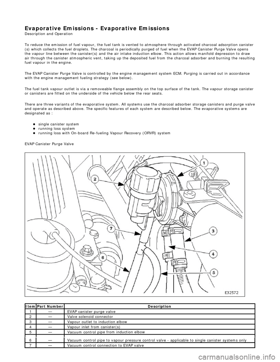
EVAP Canister Purge Valve
Ite
m
Par
t
Number
De
scr
iption
1—EVAP canister purge v
alve
2—Valve s
olenoid connector
3—Vapour outlet to indu
ction elbow
4—Vapour
inlet from canister(s)
5—Vacuum contro
l pi
pe from induction elbow
6—Vacuum contro
l pi
pe to vapour pressure control va
lve - applicable to single canister systems only
7—Vacuum
control connection to EVAP valve
Page 1152 of 2490
The ru nning loss
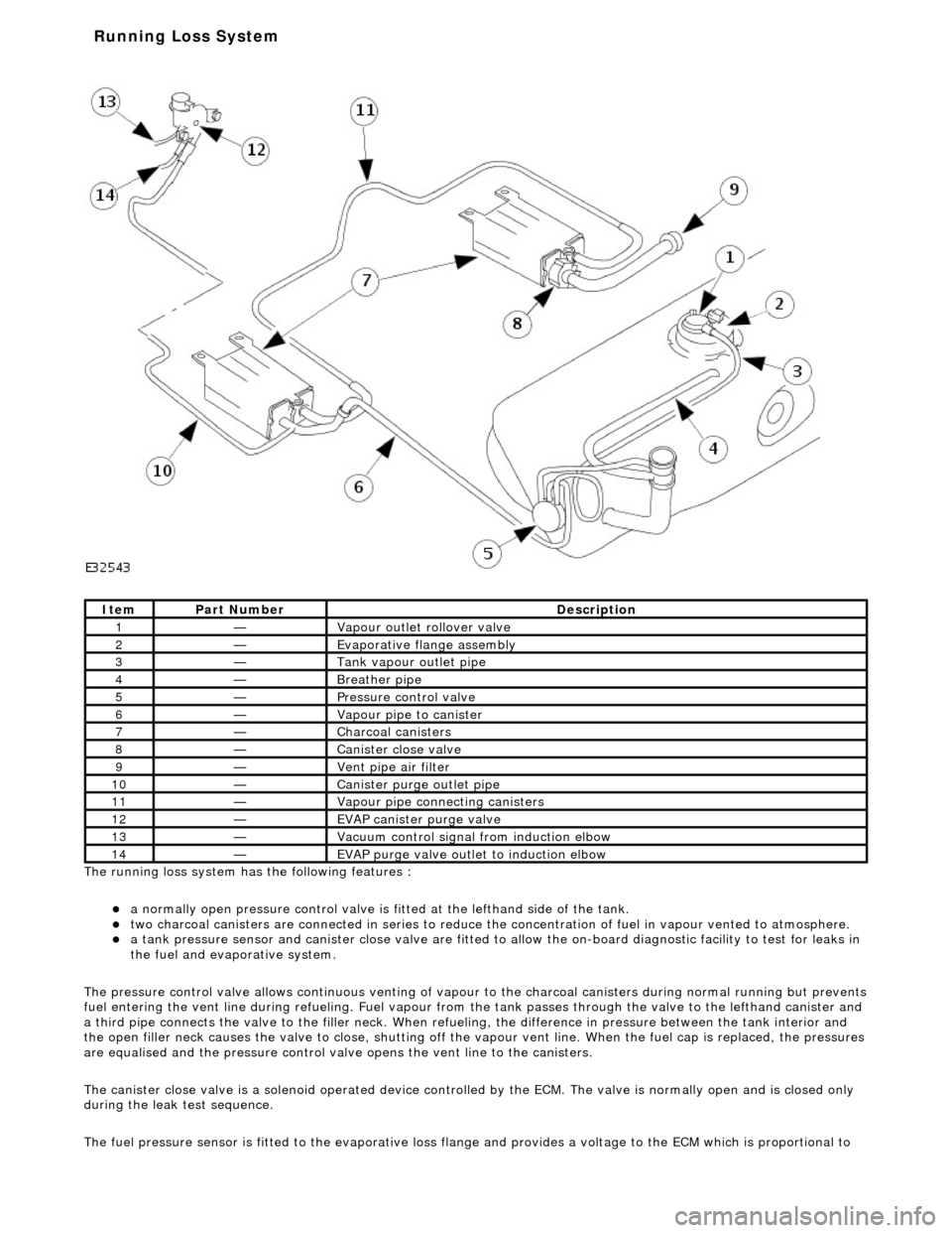
system has the following features :
a
normall
y open pressure control valve is fi
tted at the lefthand side of the tank.
two charcoal
canisters are connected in series to reduce th
e concentration of fuel in vapour vented to atmosphere.
a t
ank pressure sensor and canister close
valve are fitted to allow the on-board di agnostic facility to test for leaks in
the fuel and evaporative system.
The pressure control valve allows continuo us venting of vapour to the charcoal canisters during normal running but prevents
fuel entering the vent line duri ng refueling. Fuel vapour from the tank passes through the valve to the lefthand canister and
a third pipe connects the valve to the fill er neck. When refueling, the difference in pressure betw een the tank interior and
the open filler neck causes the valve to cl ose, shutting off the vapour vent line. Wh en the fuel cap is replaced, the pressures
are equalised and the pressure control valve opens the vent line to the canisters.
The canister close valve is a solenoid operated device controlled by the ECM. The valve is normally open and is closed only
during the leak test sequence.
The fuel pressure sensor is fitted to th e evaporative loss flange and provides a volt age to the ECM which is proportional to
Ite
m
Par
t
Number
De
scr
iption
1—Vapour outl
et rol
lover valve
2—Evaporative flan
ge assembly
3—Tank vapour outlet pipe
4—Breather pipe
5—Pressure control
valve
6—Vapour pipe to canister
7—Charcoal cani
sters
8—Cani
st
er close valve
9—Vent pi
pe ai
r filter
10—Canister purge ou
tlet pipe
11—Vapour pipe conn
ecting canisters
12—EVAP canister purge v
a
lve
13—Vacuu
m
control signal from induction elbow
14—EVAP pu
rge valve outlet to induction elbow
Running Loss Sys
tem
Page 1161 of 2490
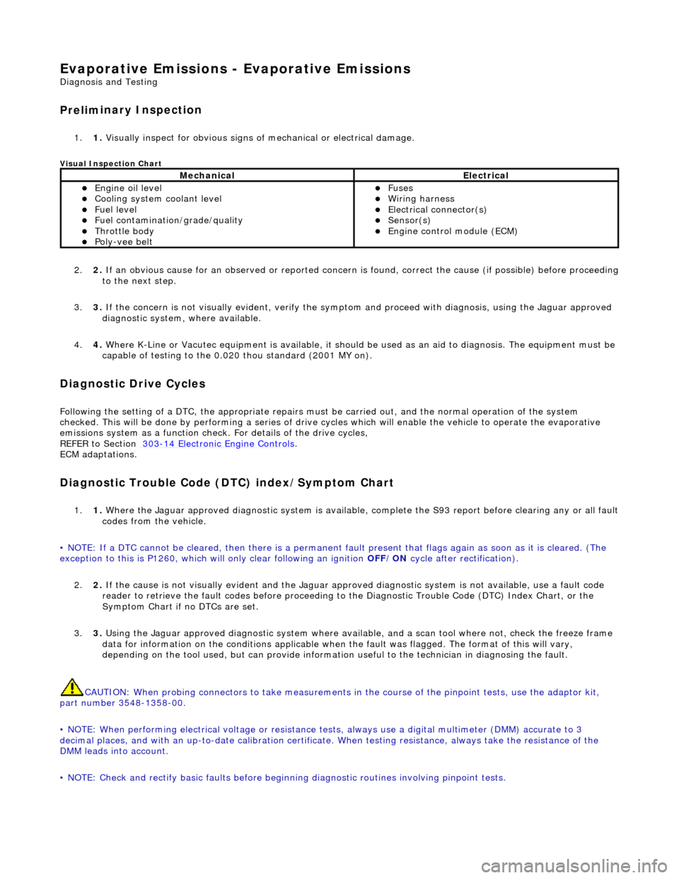
E
vaporative Emissions - Evaporative Emissions
D
iagnosis and Testing
Prelim
inary Inspection
1.
1. Vis
ually inspect for obvious signs of mechanical or electrical damage.
V
isual Inspection Chart
2.
2. If
an obvious cause for an observed or
reported concern is found, correct th e cause (if possible) before proceeding
to the next step.
3. 3. If the concern is not visually evident, verify the symptom and proceed with diagnosis, using the Jaguar approved
diagnostic system, where available.
4. 4. Where K-Line or Vacutec equipment is available, it should be used as an aid to diagnosis. The equipment must be
capable of testing to the 0.020 thou standard (2001 MY on).
Diagnostic Drive Cycles
Following th
e setting of a DTC, the appropriate repairs must
be carried out, and the normal operation of the system
checked. This will be done by performing a series of drive cycles which will enable the vehicle to operate the evaporative
emissions system as a function check. For details of the drive cycles,
REFER to Section 303
-1
4 Electronic Engine Controls
.
ECM adapt
ations.
Diagnostic Trouble Code
(D
TC) index/Symptom Chart
1.
1. Wh
ere the Jaguar approved diagnostic sy
stem is available, complete the S93 report before clearing any or all fault
codes from the vehicle.
• NOTE: If a DTC cannot be cleared, then there is a permanent fault present that flag s again as soon as it is cleared. (The
exception to this is P1260, which will only clear following an ignition OFF/ON cycle after rectification).
2. 2. If the cause is not visually evident and the Jaguar approv ed diagnostic system is not available, use a fault code
reader to retrieve the fault codes be fore proceeding to the Diagnostic Trou ble Code (DTC) Index Chart, or the
Symptom Chart if no DTCs are set.
3. 3. Using the Jaguar approved diagnostic system where available, and a scan tool where not, check the freeze frame
data for information on the conditions applicable when the fault was flagged. The format of this will vary,
depending on the tool used, but can pr ovide information useful to the technician in diagnosing the fault.
CAUTION: When probing connectors to take measurements in the course of the pinpoint tests, use the adaptor kit,
part number 3548-1358-00.
• NOTE: When performing electrical voltag e or resistance tests, always use a digital multimeter (DMM) accurate to 3
decimal places, and with an up-t o-date calibration certificate. When testing resistance, always take the resistance of the
DMM leads into account.
• NOTE: Check and rectify basic faults before beginning diagnostic ro utines involving pinpoint tests.
MechanicalElectrical
Engi
ne oil level
Coo
ling system coolant level
Fue
l level
Fuel contaminatio
n
/grade/quality
Throttle body Poly
-vee belt
F
uses
W
iring harness
E
lectrical connector(s)
Sens
or(s)
Engine
control module (ECM)
Page 1162 of 2490
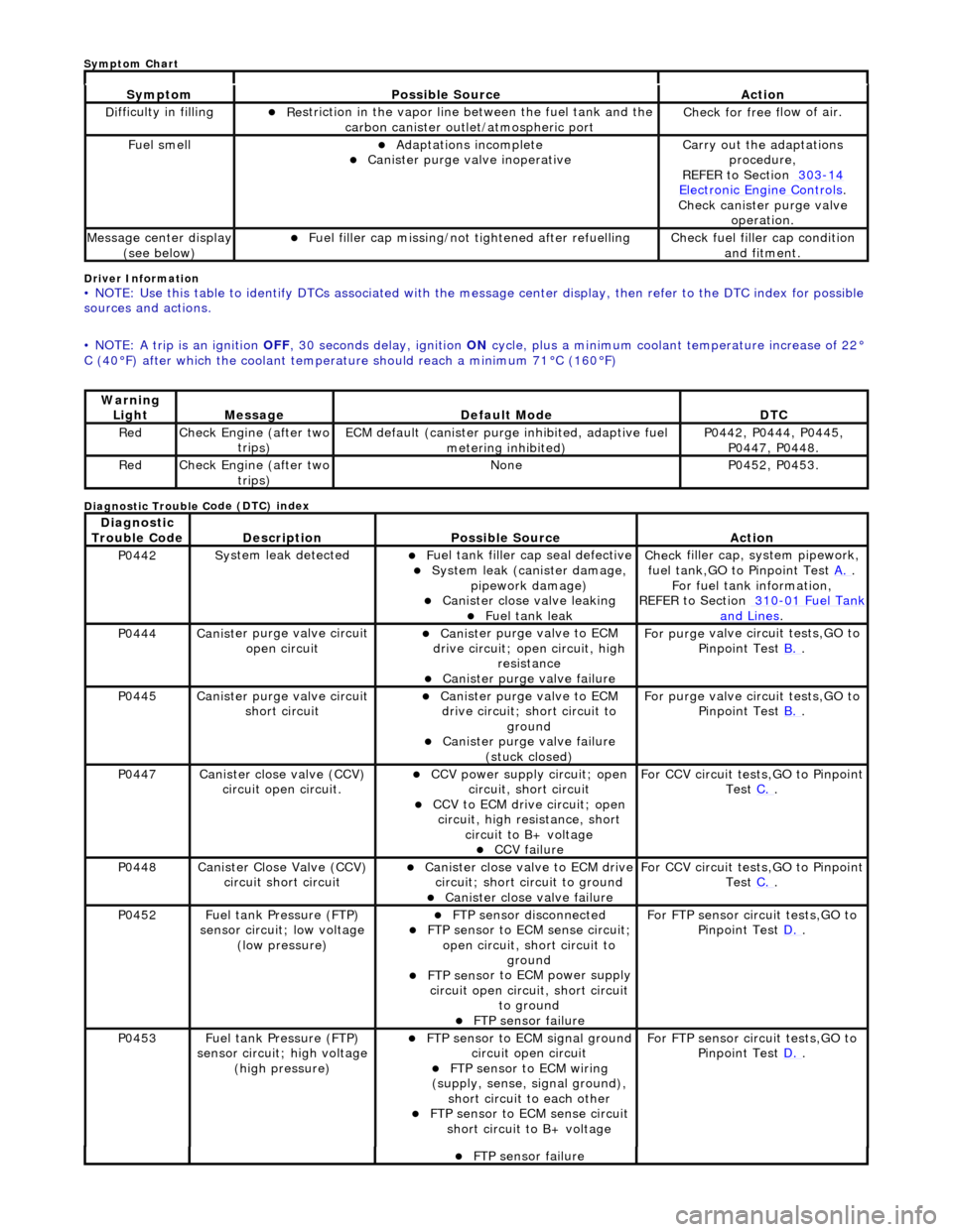
Driver Info
rmation
•
NOTE: Use this table to identify DTCs associated with the me
ssage center display, then refer to the DTC index for possible
sources and actions.
• NOTE: A trip is an ignition OFF, 30 seconds delay, ignition ON cycle, plus a minimum coolant temperature increase of 22°
C (40°F) after which the coolant temperat ure should reach a minimum 71°C (160°F)
Diagnostic Trouble C
ode (DTC) index
Sy
m
ptom
Possib
l
e Source
Acti
o
n
D
i
fficulty in filling
R
e
striction in the vapor line between the fuel tank and the
carbon canister outlet/atmospheric port
Check f or free f
low of air.
F
u
el smell
Adaptat
i
ons incomplete
Cani
st
er purge valve inoperative
Carry
o
ut the adaptations
procedure,
REFER to Section 303
-14 Ele c
tronic Engine Controls
.
Chec k cani
ster purge valve
operation.
M e
ssage center display
(see below)
Fue l
filler cap missing/not
tightened after refuelling
Check fu
el filler cap condition
and fitment.
Warning Li
ght
Mess
age Defaul
t Mode
DT
C
RedCheck Engine (after two
trip
s)
ECM de
fa
ult (canister purge inhibited, adaptive fuel
metering inhibited)
P0442,
P0444, P0445,
P0447, P0448.
Re dCheck Engine (after two
trip
s)
No
neP04 52,
P0453.
Di
agno
stic
Trouble Code
De scr
iption
Possib
l
e Source
Acti
o
n
P0442Sy
st
em leak detected
F
u
el tank filler cap seal defective
Sy
ste
m leak (c
anister damage,
pipework damage)
Cani st
er close valve leaking
F
u
el tank leak
Chec
k fi
ller cap,
system pipework,
fuel tank,GO to Pinpoint Test A.
.
F o
r fuel tank information,
REFER to Section 310
-01 Fu
el Tank
and Lines.
P0444Canist
er purge valve circuit
open circuit
Cani st
er purge valve to ECM
drive circuit; open circuit, high
resistance
Cani st
er purge valve failure
F
or purge
valve circuit tests,GO to
Pinpoint Test B.
.
P0445Canist
er purge valve circuit
short circuit
Cani st
er purge valve to ECM
drive circuit; short circuit to ground
Canist
er purge valve failure
(stuck closed)
F or purge
valve circuit tests,GO to
Pinpoint Test B.
.
P0447Canist
er close valve (CCV)
circuit open circuit.
CCV power su pply ci
rcuit; open
circuit, short circuit
CCV to ECM drive circuit;
open
circuit, high resistance, short circuit to B+ voltage
CCV failure
Fo
r CCV circuit tests,GO to Pinpoint
Test C.
.
P0448Canist
er Close Valve (CCV)
circuit short circuit
Cani st
er close valve to ECM drive
circuit; short circuit to ground
Cani st
er close valve failure
F
o
r CCV circuit tests,GO to Pinpoint
Test C.
.
P0452 Fu
el tank Pressure (FTP)
sensor circuit; low voltage (low pressure)
FTP sen
sor disconnected
FTP sen
sor to ECM sense circuit;
open circuit, short circuit to ground
FTP sens
or to ECM power supply
circuit open circuit, short circuit to ground
FT
P sensor failure
For FT
P se
nsor circuit tests,GO to
Pinpoint Test D.
.
P0453Fu
el tank Pressure (FTP)
sensor circuit; high voltage
(high pressure)
FTP sen
sor to ECM signal ground
circuit open circuit
F T
P sensor to ECM wiring
(supply, sense, signal ground),
short circuit to each other
FTP sen
sor to ECM sense circuit
short circuit to B+ voltage
For FT P se
nsor circuit tests,GO to
Pinpoint Test D.
.
FT
P sensor failure
Sym
ptom Chart
Page 1191 of 2490
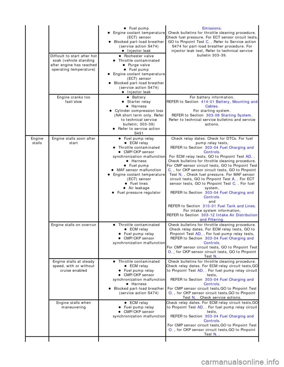
Fue
l pump
Engine coolan
t temperature
(ECT) sensor
Blocked part-load breather (
service action S474)
Injec
tor leak
Emiss
ions
.
Check bull
etins for throttle cleaning procedure.
Check fuel pressure. For ECT sensor circuit tests,
GO to Pinpoint Test C.
. Refer to Servi
ce action
S474 for part-load breather procedure. For
injector leak test, Refer to technical service bulletin 303-39.
D
ifficult to start after hot
soak (vehicle standing
after engine has reached operating temperature)
Roc
hester valve
Thr
ottle contaminated
Purge
valve
Fue
l pump
Engine coolan
t temperature
(ECT) sensor
Blocked part-load breather (
service action S474)
Injec
tor leak
Engine cranks too
fa
st/slow
Batt
ery
Starter relay Harness Cyl
inder compression loss
(NA short term only. Refer to technical service bulletin; 303-39)
R
efer to service action
S491
F
or battery information,
REFER to Section 414
-0
1 Battery, Mounting and
Cables.
F
or starting system.
REFER to Section 303
-06 Sta
rting System
.
R
efer to technical servic
e bulletins and service
actions.
Engine
stalls
Engine st
alls soon after
start
F
uel pump relay
ECM relay Thr
ottle contaminated
CMP/CKP sen
sor
synchronization malfunction
Harness Fue
l pump
MAF
sensor malfunction
Engine coolan
t temperature
(ECT) sensor
Fue
l lines
Air leakage
F
uel pressure regulator
Check r
elay dates. Chec
k for DTCs. For fuel
pump relay tests,
REFER to Section 303
-0
4 Fuel Charging and
Controls.
F
or ECM relay tests, GO to Pinpoint Test
AD.
.
Check bull
etins for throttle cleaning procedure.
For CMP sensor circuit test s, GO to Pinpoint Test
C.
, for
CKP sensor circuit tests, GO to Pinpoint
Test N.
. Check fuel
pressure. For MAF sensor
circuit tests, GO to Pinpoint Test A.
. For EC
T
sensor tests, GO to Pinpoint Test C.
. F
or fuel
system,
REFER to Section 303
-0
4 Fuel Charging and
Controls.
and
REF
ER to Section 310
-0
1 Fuel Tank and Lines
. F
or intake system information,
REFER to Section 303
-1
2 Intake Air Distribution
and F
iltering
.
Engine
stalls on overrun
Thr
ottle contaminated
ECM relay F
uel pump relay
CMP/CKP sen
sor
synchronization malfunction
Check bull
etins for throttle cleaning procedure.
Check relay dates. For ECM relay tests, GO to Pinpoint Test AD.
. F
or fuel pump relay tests,
REFER to Section 303
-0
4 Fuel Charging and
Controls.
F
or CMP sensor circuit test
s, GO to Pinpoint Test
O.
, for
CKP sensor circuit tests, GO to Pinpoint
Test N.
.
E
ngine stalls at steady
speed, with or without cruise enabled
Thr
ottle contaminated
ECM relay F
uel pump relay
CMP/CKP sen
sor
synchronization malfunction
Harness Blocked part-load breather
(
service action S474)
Check bull
etins for throttle cleaning procedure.
Check relay dates. For EC M relay circuit tests,GO
to Pinpoint Test AD.
. F
or fuel pump relay circuit
tests,
REFER to Section 303
-0
4 Fuel Charging and
Controls.
F
or CMP sensor circuit test
s,GO to Pinpoint Test
O.
, for
CKP sensor circuit tests,GO to Pinpoint
Test N.
. Che
ck service actions.
Engine st
alls when
maneuvering
ECM relay F
uel pump relay
CMP/CKP sen
sor
synchronization malfunction
Check r
elay dates. For EC
M relay circuit tests,GO
to Pinpoint Test AD.
. F
or fuel pump relay circuit
tests,
REFER to Section 303
-0
4 Fuel Charging and
Controls.
F
or CMP sensor circuit test
s,GO to Pinpoint Test
O.
, for
CKP sensor circuit tests,GO to Pinpoint
Test N.
.
Page 1197 of 2490
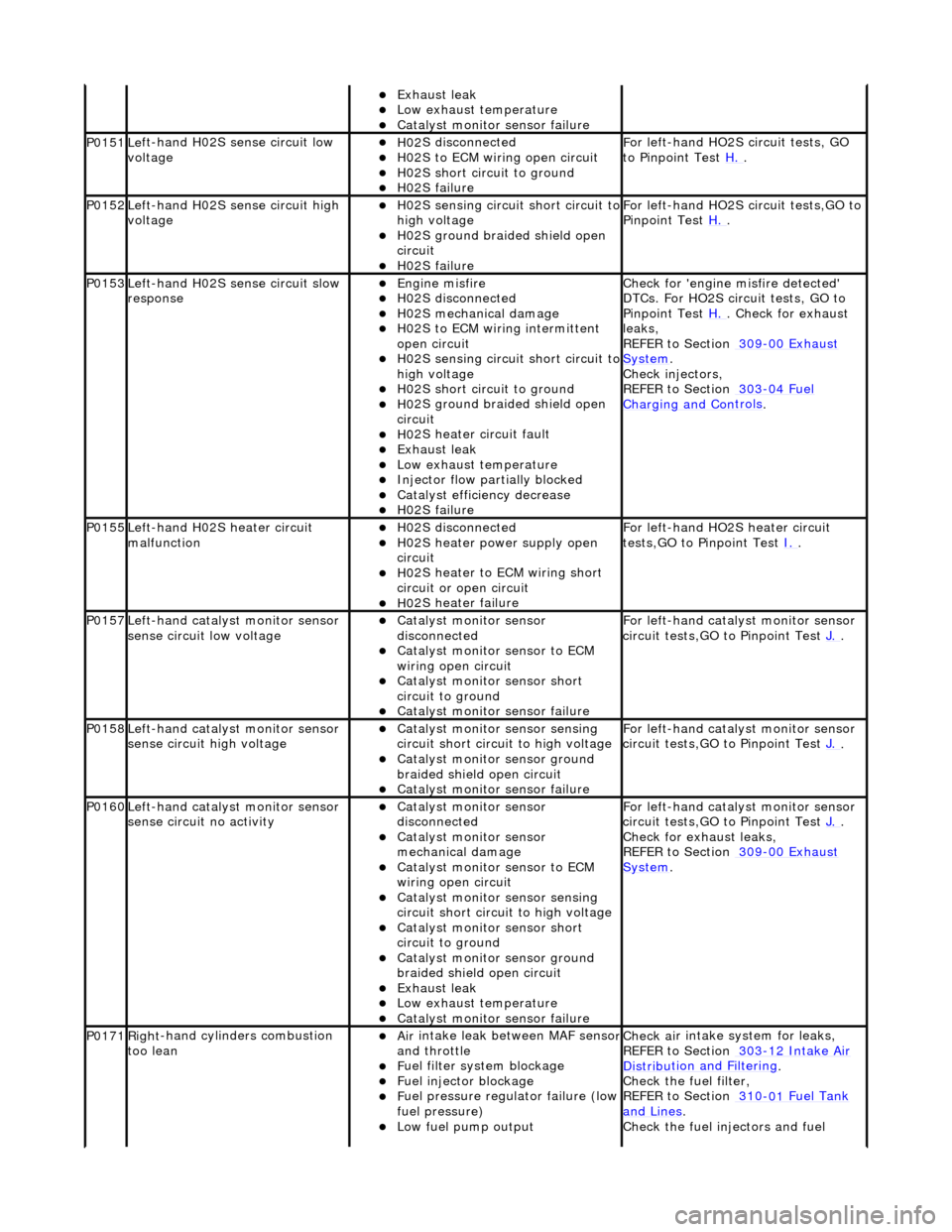
Exhaus
t leak
Low e
xhaust temperature
Cat
alyst monitor sensor failure
P0151Le
ft-hand H02S sense circuit low
voltage
H02
S disconnected
H0
2S to ECM wiring open circuit
H0
2S short circuit to ground
H0
2S failure
F
or left-hand HO2S circuit tests, GO
to Pinpoint Test H.
.
P0152Le
ft-hand H02S sense circuit high
voltage
H02
S sensing circuit short circuit to
high voltage
H0
2S ground braided shield open
circuit
H0
2S failure
F
or left-hand HO2S circuit tests,GO to
Pinpoint Test H.
.
P0153Le
ft-hand H02S sense circuit slow
response
Engine
misfire
H02
S disconnected
H0
2S mechanical damage
H0
2S to ECM wiring intermittent
open circuit
H02
S sensing circuit short circuit to
high voltage
H0
2S short circuit to ground
H0
2S ground braided shield open
circuit
H0
2S heater circuit fault
Exhaus
t leak
Low e
xhaust temperature
Injector fl
ow partially blocked
Catal
yst efficiency decrease
H0
2S failure
Chec
k for 'engine misfire detected'
DTCs. For HO2S circ uit tests, GO to
Pinpoint Test H.
. Check for exhaust
leak
s,
REFER to Section 309
-00
Exhaust
Sy
stem
.
Chec
k injectors,
REFER to Section 303
-04
Fuel
Charging and Con
trols
.
P0155Left-hand H02S heater
circuit
malfunction
H02
S disconnected
H0
2S heater power supply open
circuit
H0
2S heater to ECM wiring short
circuit or open circuit
H0
2S heater failure
F
or left-hand HO2S heater circuit
tests,GO to Pinpoint Test I.
.
P0157Le
ft-hand catalyst monitor sensor
sense circuit low voltage
Catal
yst monitor sensor
disconnected
Catal
yst monitor sensor to ECM
wiring open circuit
Catal
yst monitor sensor short
circuit to ground
Cat
alyst monitor sensor failure
F
or left-hand catalyst monitor sensor
circuit tests,GO to Pinpoint Test J.
.
P0158Le
ft-hand catalyst monitor sensor
sense circuit high voltage
Catal
yst monitor sensor sensing
circuit short circuit to high voltage
Catalyst
monitor sensor ground
braided shield open circuit
Cat
alyst monitor sensor failure
F
or left-hand catalyst monitor sensor
circuit tests,GO to Pinpoint Test J.
.
P0160Le
ft-hand catalyst monitor sensor
sense circuit no activity
Catal
yst monitor sensor
disconnected
Catal
yst monitor sensor
mechanical damage
Catal
yst monitor sensor to ECM
wiring open circuit
Catal
yst monitor sensor sensing
circuit short circuit to high voltage
Catal
yst monitor sensor short
circuit to ground
Catalyst
monitor sensor ground
braided shield open circuit
Exhaus
t leak
Low e
xhaust temperature
Cat
alyst monitor sensor failure
F
or left-hand catalyst monitor sensor
circuit tests,GO to Pinpoint Test J.
.
Check f
or exhaust leaks,
REFER to Section 309
-00
Exhaust
Sy
stem
.
P0171Right
-hand cylinders combustion
too lean
Air
intake leak between MAF senso
r and th
rottle
F
uel filter system blockage
F
uel injector blockage
F
uel pressure regulator failure (low
fuel pressure)
Low f
uel pump output
Check ai
r intake system for leaks,
REFER to Section 303
-1
2 Intake Air
Distribu
tion and Filtering
.
Check the fuel fi
lter,
REFER to Section 310
-01
Fuel Tank
and Lines.
Chec
k the fuel injectors and fuel