1998 JAGUAR X308 fuel line
[x] Cancel search: fuel linePage 1198 of 2490
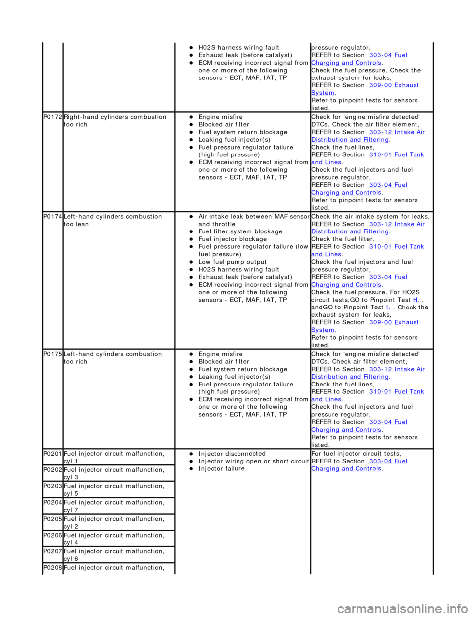
H02S harness wiri
ng fault
E
x
haust leak (before catalyst)
ECM receivi
n
g incorrect signal from
one or more of the following
sensors - ECT, MAF, IAT, TP
pr essure regulator,
REF
ER to Section 303
-04
Fu
el
Charging and Con
t
rols
.
Chec k the
fuel pressure. Check the
exhaust system for leaks,
REFER to Section 309
-00 Ex
haust
Sy
ste
m
.
R e
fer to pinpoint tests for sensors
listed.
P0172Right -
hand cylinders combustion
too rich
Engine m
isfire
Bl
ocked air
filter
F
u
el system return blockage
Leak
i
ng fuel injector(s)
F
u
el pressure regulator failure
(high fuel pressure)
ECM receivi n
g incorrect signal from
one or more of the following
sensors - ECT, MAF, IAT, TP
Chec k for 'en
gine misfire detected'
DTCs. Check the air filter element,
REFER to Section 303
-1 2
Intake Air
Distribu
tion and Filterin
g
.
Chec k the
fuel lines,
REFER to Section 310
-01 Fu
el Tank
and Lines.
Chec k the
fuel injectors and fuel
pressure regulator,
REFER to Section 303
-04 Fu
el
Charging and Con
t
rols
.
R e
fer to pinpoint tests for sensors
listed.
P0174L e
ft-hand cylinders combustion
too lean
Air in
take leak between MAF senso
r and th
ro
ttle
F
u
el filter system blockage
F
u
el injector blockage
F
u
el pressure regulator failure (low
fuel pressure)
Low fu
el pump output
H0
2S harness wiri
ng fault
E
x
haust leak (before catalyst)
ECM receivi
n
g incorrect signal from
one or more of the following
sensors - ECT, MAF, IAT, TP
Check the ai r intak
e system for leaks,
REFER to Section 303
-1 2
Intake Air
Distribu
tion and Filterin
g
.
Check the fuel fi lter,
REF
ER to Section 310
-01
Fu
el Tank
and Lines.
Chec k the
fuel injectors and fuel
pressure regulator,
REFER to Section 303
-04 Fu
el
Charging and Con
t
rols
.
Chec k the
fuel pressure. For HO2S
circuit tests,GO to Pinpoint Test H.
,
a n
dGO to Pinpoint Test
I.
. Check
the
exhaust system for leaks,
REFER to Section 309
-00 Ex
haust
Sy
ste
m
.
R e
fer to pinpoint tests for sensors
listed.
P0175L e
ft-hand cylinders combustion
too rich
Engine m
isfire
Bl
ocked air
filter
F
u
el system return blockage
Leak
i
ng fuel injector(s)
F
u
el pressure regulator failure
(high fuel pressure)
ECM receivi n
g incorrect signal from
one or more of the following
sensors - ECT, MAF, IAT, TP
Chec k for 'en
gine misfire detected'
DTCs. Check air filter element,
REFER to Section 303
-1 2
Intake Air
Distribu
tion and Filterin
g
.
Chec k the
fuel lines,
REFER to Section 310
-01 Fu
el Tank
and Lines.
Chec k the
fuel injectors and fuel
pressure regulator,
REFER to Section 303
-04 Fu
el
Charging and Cont
rols
.
Re
fer to pinpoint tests for sensors
listed.
P0201 Fu
el injector circuit malfunction,
cyl 1
Injector discon n
ected
Inject
or wir
ing open or short circuit
Injector fail
ure
F
o
r fuel injector
circuit tests,
REFER to Section 303
-04 Fu
el
Charging and Con
t
rols
. P0202F
u
el injector circuit malfunction,
cyl 3
P0203F u
el injector circuit malfunction,
cyl 5
P0204F u
el injector circuit malfunction,
cyl 7
P0205F u
el injector circuit malfunction,
cyl 2
P0206F u
el injector circuit malfunction,
cyl 4
P0207F u
el injector circuit malfunction,
cyl 6
P0208F u
el injector circuit malfunction,
Page 1688 of 2490
Fuel System - General Inform
ation - Fuel System
Description an
d Operation
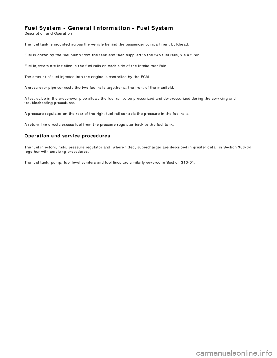
The fuel tank is mounted across the vehicle behind the passenger compartment bulkhead.
Fuel is drawn by the fuel pump from the tank and then supplied to the two fuel rails, via a filter.
Fuel injectors are installed in the fuel ra ils on each side of the intake manifold.
The amount of fuel injected into th e engine is controlled by the ECM.
A cross-over pipe connects the two fuel ra ils together at the front of the manifold.
A test valve in the cross-over pipe allo ws the fuel rail to be pressurized and de-pressurized during the servicing and
troubleshooting procedures.
A pressure regulator on the rear of the right fuel rail controls the pressure in the fuel rails.
A return line directs excess fuel from the pressure regulator back to the fuel tank.
Operation and service procedures
The fuel injector
s, rails, pres
sure regulator and, wher e fitted, supercharger are described in greater detail in Section 303-04
together with servicing procedures.
The fuel tank, pump, fuel level senders and fuel lines are similarly covered in Section 310-01.
Page 1689 of 2490
Fuel System - General Information - Fuel System Pre
ssure Check
Gen
eral Procedures
WARNING: Working on the fuel system re sults in fuel and fuel vapor being present in the atmosphere. Fuel vapor is
extremely flammable, hence great care must be taken whilst working on the fuel system. Adhere strictly to the following
precautions:
D
o not smoke in the work area
Di
splay
NO SMOKING signs around the work area
D
isconnect the battery before
working on the fuel system
Av
oid sparks
Make sure sui
table fire ex
tinguishers are at hand
Make sure absor
bent material is at
hand to soak up any spillage
Make sure the work area is
well ventilated
M
ake sure that the gauge is correctly conn
ected, and that all connections are secure BEFORE starting the engine
DO N
OT
disconnect the gauge from the schrader valve while the engine is running
Make su
re the schrader valve reseals once the gauge is disconnected
• NOTE: Depending on the design of the ga uge set, there may be a drain valve and tube. Make sure this valve is closed, and
the drain tube placed in a suitable container BEFORE connecting the gauge to the schrader valve.
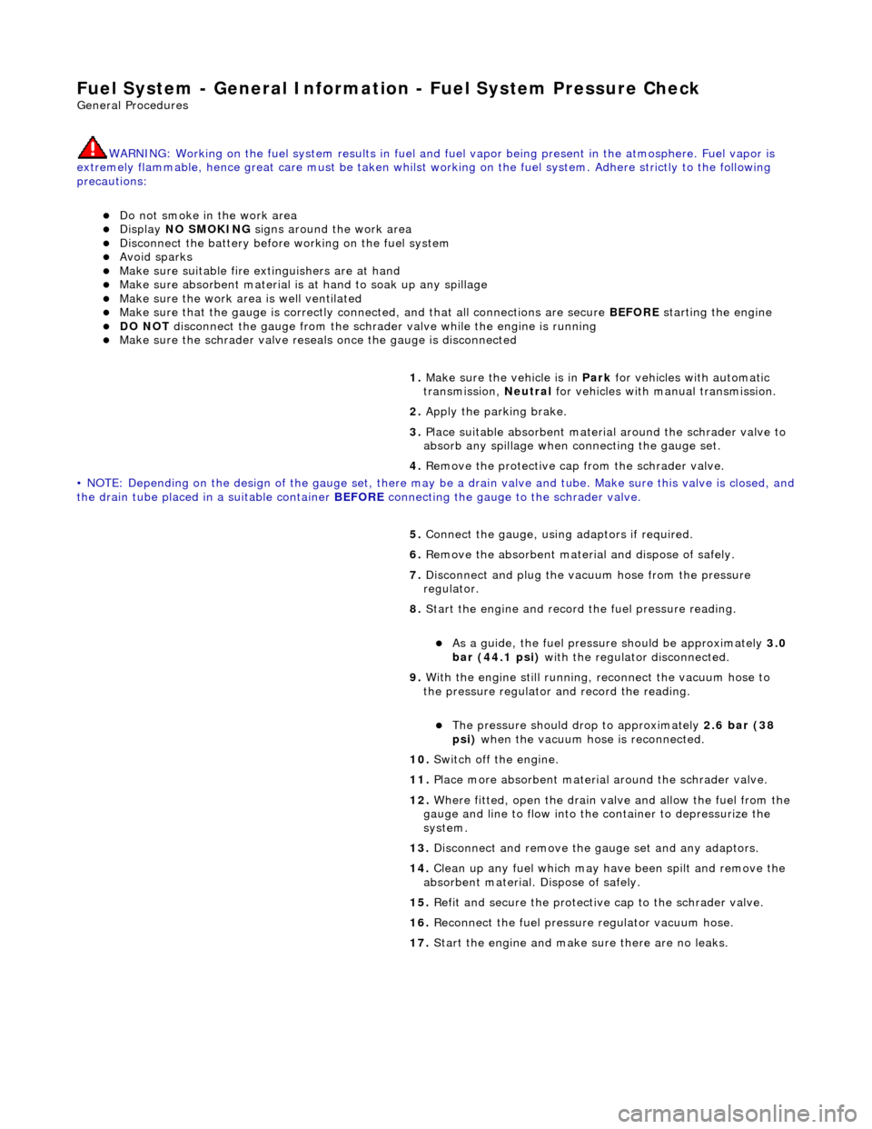
1. Make sure the vehi
cle is in
Park for vehicles with automatic
transmission, Neutral for vehicles with manual transmission.
2. Apply the parking brake.
3. Place suitable absorbent material around the schrader valve to
absorb any spillage when connecting the gauge set.
4. Remove the protective cap from the schrader valve.
5. Connect the gauge, using adaptors if required.
6. Remove the absorbent material and dispose of safely.
7. Disconnect and plug the vacuum hose from the pressure
regulator.
8. Start the engine and record the fuel pressure reading.
As a gui
de, the fuel pressu
re should be approximately 3.0
bar (44.1 psi) with the regulator disconnected.
9. With the engine still running, reconnect the vacuum hose to
the pressure regulator an d record the reading.
Th
e pressure should dr
op to approximately 2.6 bar (38
psi) when the vacuum hose is reconnected.
10. Switch off the engine.
11. Place more absorbent material around the schrader valve.
12. Where fitted, open the drain valve and allow the fuel from the
gauge and line to flow into the container to depressurize the
system.
13. Disconnect and remove the gauge set and any adaptors.
14. Clean up any fuel which may have been spilt and remove the
absorbent material. Dispose of safely.
15. Refit and secure the protective cap to the schrader valve.
16. Reconnect the fuel pressure regulator vacuum hose.
17. Start the engine and make sure there are no leaks.
Page 1692 of 2490
Fuel Tank and Lines - Fuel Tank and Li
nes
Description an
d Operation
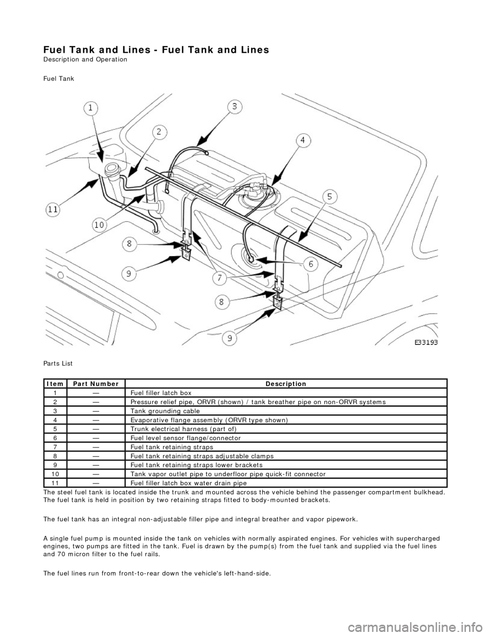
Fuel Tank
Parts List
The steel fuel tank is located inside the trunk and mounted across the vehicle behind the passenger compartment bulkhead.
The fuel tank is held in posi tion by two retaining straps fi tted to body-mounted brackets.
The fuel tank has an integral non-adjustable fill er pipe and integral breather and vapor pipework.
A single fuel pump is mounted inside the tank on vehicles with normally aspirated engines. For vehicles with supercharged
engines, two pumps are fitted in the tank. Fuel is drawn by the pump(s) from the fuel tank and supplied via the fuel lines
and 70 micron filter to the fuel rails.
The fuel lines run from front-to-rear down the vehicle's left-hand-side.
Ite
m
Part
Number
Descr
iption
1—Fu
el filler latch box
2—Pressure reli
ef pipe, ORVR
(shown) / tank breather pipe on non-ORVR systems
3—Tank grounding
cable
4—Evaporative flan
ge assembly
(ORVR type shown)
5—Trunk elec
trical harne
ss (part of)
6—Fue
l
level sensor
flange/connector
7—Fu
el tank retaining straps
8—F
u
el tank retaining stra
ps adjustable clamps
9—Fu
el tank retaining straps lower brackets
10—Tank vapor outlet pipe to un
derflo
or pipe quick-fit connector
11—F
u
el filler latch bo
x water drain pipe
Page 1693 of 2490
Filler Cap and P
ipe
The fuel
filler cap with bayonet-type fixi
ng is located beneath a remote-release sp ring-latched lid on the rear saddle panel
on the left-hand-side of the vehicle.
Fuel Pum
p
The fu
el pump(s) is energized by an ECM co
ntrolled relay. Fuel is drawn by this pu mp and supplied to the fuel injectors via
the fuel line, filter and fuel rails.
Servicing of the fuel pump re quires fuel tank removal.
Ev
aporative Loss Flange Assembly
The evaporative-loss flan
ge asse
mbly is mounted centrally on top of the tank. The flange assembly consists of a removeable
steel cap which mounts the evaporative emissions system vapor outlet valves and, if applicable, a pressure sensor. The
external electrical supply to th e fuel pump(s) is also made via a connector on the flange.
The flange assembly is fixed to the tank by a locking ring which is turned usin g special tool JD-174. A seal is fitted between
the flange assembly and the tank. Three di fferent flange assemblies are applicable according to the evaporative emission
system fitted to the vehicle. The fl ange size and fixing are identical fo r the three systems, as described.
Removal of the evaporative flange assembly is necessary to gain access to th e fuel pump(s) and other internal components.
To remove the evaporative fl ange assembly the fuel tank must first be removed.
The evaporative flange variant assemblies are described, together with service information, in Section 303-13.
Fuel R
eturn
Excess fuel
is directed back to
the fuel tank via a return line.
Fuel Pum
p Relay
The
fuel pump relay,
under control of the ECM, switches power to the fuel pump motor.
I
nertia Fuel Shutoff (IFS) Switch
The IF
S switch is located in the right-hand
side footwell behind the footboard carpet . When activated the switch isolates the
ignition system and fuel pump, releases any locked doors and disables unnecessary electrical systems. The system can be
reset by pressing down the flexible cover on the top of the switch.
• NOTE: The doors will not unlock if the IFS switch is tripped when the ignition switch is in position '0'.
Page 1698 of 2490
Fuel Tank and Lines - Fuel Tank and Li
nes
D
iagn
osis and Testing
Sym
p
tom Chart
Sy
m
ptom Chart
Pinpoint test A: P1230
S
p
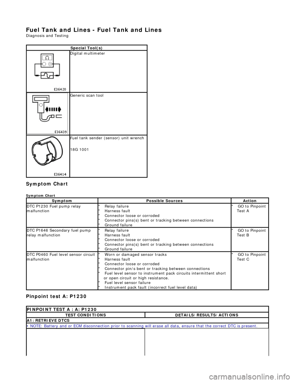
ecial Tool(s)
D
i
gital multimeter
Generi
c scan tool
F
u
el tank sender (sensor) unit wrench
18G 1001
Sy m
ptom
Possib
l
e Sources
Acti
o
n
D
T
C P1230 Fuel pump relay
malfunction
Re lay
failure
Harness fault
Connector loose or corroded
Connector pins(s) bent or tracking between connections
Ground failure
*
*
*
*
*
GO to Pinpoint
Test A
*
D
T
C P1646 Secondary fuel pump
relay malfunction
Re lay
failure
Harness fault
Connector loose or corroded
Connector pins(s) bent or tracking between connections
Ground failure
*
*
*
*
*
GO to Pinpoint
Test B
*
D
T
C P0460 Fuel level sensor circuit
malfunction
Worn
or damaged sensor tracks
Harness fault
Connector loose or corroded
Connector pin/s bent or tracking between connections
Fuel level sensor to instrument pack circui ts intermittent short
or open circuit or high resistance. Fuel level sensor failure
Instrument pack fault (inc orrect fuel level data)
*
*
*
*
*
*
*
GO to Pinpoint
Test C
*
P
INPOINT TES
T A : A: P1230
T
E
ST CONDITIONS
D
E
TAILS/RESULTS/ACTIONS
A1
: RETRIEV
E DTCS
•
NOTE
: Battery and or ECM disconnection prior to scanning wi
ll erase all data, ensure that the correct DTC is present.
Page 1732 of 2490
Fu
el Tank and Lines - Fuel Level Sensor
Remov
a
l and Installation
Removal
Ins
tallation
1.
WA
RNING: BEFORE PROCEEDING, IT IS ESSENTIAL THAT THE
WARNING NOTES GIVEN IN SECTIO N 100-00 (UNDER THE HEADING
'SAFETY PRECAUTIONS') ARE READ AND UNDERSTOOD.
Remove the battery. For additional information, refer to Section 414
-01
Battery, Mounting and Cables
.
2.
Drain
the fuel tank using a suitable suction pump/tanker. If the On-
board Refueling Vapour Recovery (ORVR) system is fitted, refer to
Section 310
-00 Fu
el System
- Gen
e
ral Information
.
3. Remov
e the trunk front liner. For additional information, refer to
Section 501
-05 Interior Trim
and Ornamentation
.
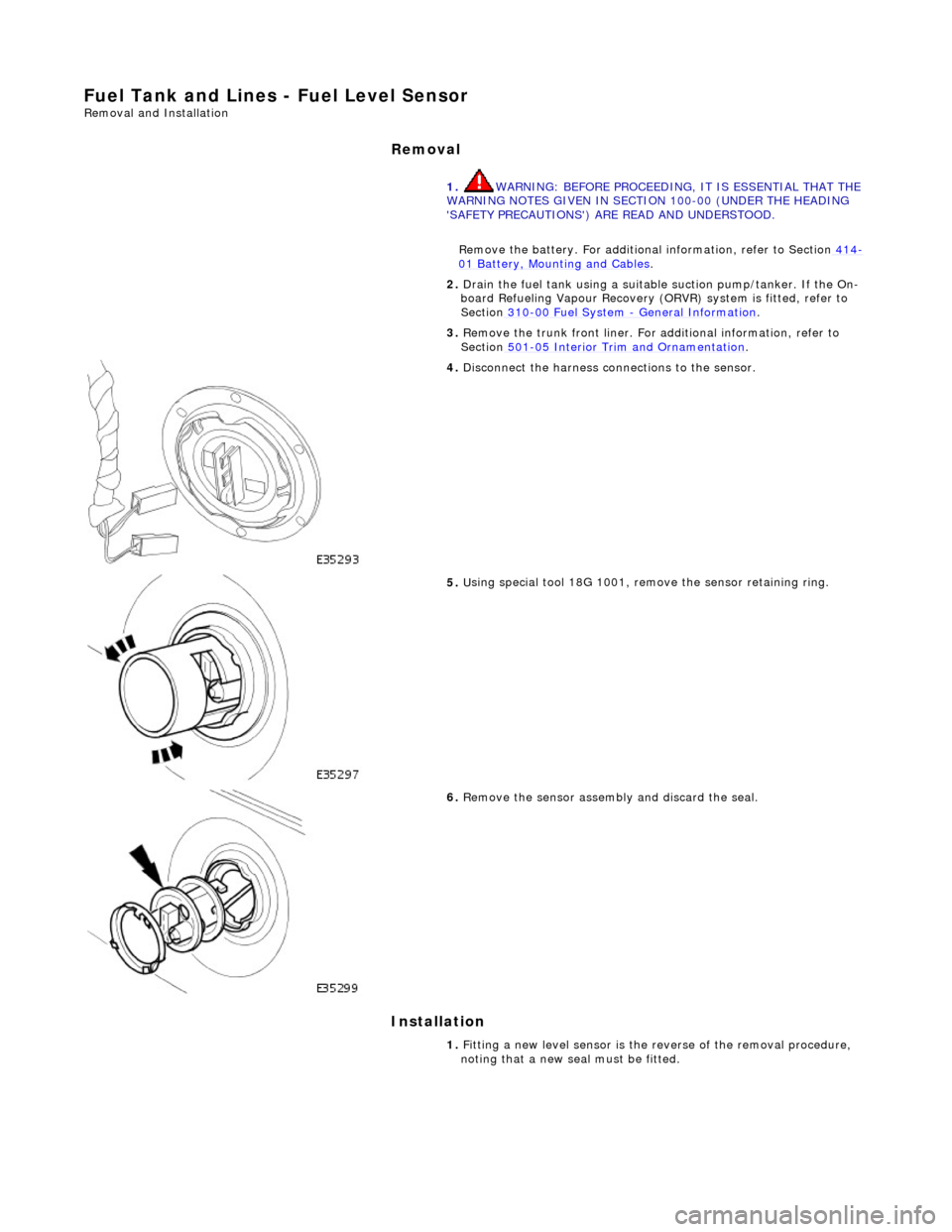
4. D
isconnect the harness co
nnections to the sensor.
5. U
sing special tool 18G 1001, remo
ve the sensor retaining ring.
6.
Remov
e the sensor assembly and discard the seal.
1. Fitting a new level sensor is the reverse of the removal procedure,
noting that a new seal must be fitted.
Page 1734 of 2490
Fuel Tank and Lines - Fuel Tank
Re
mo
val and Installation
Remov
a
l
•
NO
TE: This removal/installation procedure is applicable to all tank assembly variants.
S
p
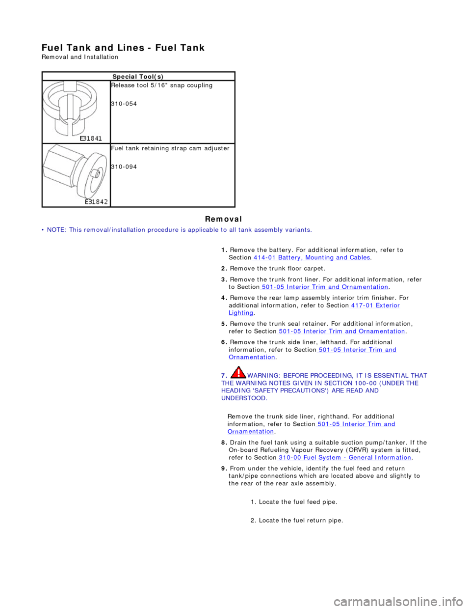
ecial Tool(s)
R
e
lease tool 5/16" snap coupling
310-054
F u
el tank retaining strap cam adjuster
310-094
1. Remove the battery. For additi onal information, refer to
Section 414
-01
Battery, Mounting and Cables
.
2. Re
move the trunk floor carpet.
3. Remove the trunk front liner. Fo r additional information, refer
to Section 501
-05
Interior Trim and Ornamentation
.
4. Re
move the rear lamp assembly interior trim finisher. For
additional information, refer to Section 417
-01
Exterior
Ligh
ting.
5. Re
move the trunk seal retainer
. For additional information,
refer to Section 501
-0 5
Interior Trim and Ornamentation
.
6. Re
move the trunk side liner, lefthand. For additional
information, refer to Section 501
-05
Interior Trim and
Or
n
amentation
.
7. WARNING: B E
FORE PROCEEDING, IT IS ESSENTIAL THAT
THE WARNING NOTES GIVEN IN SECTION 100-00 (UNDER THE
HEADING 'SAFETY PRECAUTIONS') ARE READ AND
UNDERSTOOD.
Remove the trunk side liner, righthand. For additional
information, refer to Section 501
-05
Interior Trim and
Or
n
amentation
.
8.
Drain th e fue
l tank using a suitab
le suction pump/tanker. If the
On-board Refueling Vapour Recove ry (ORVR) system is fitted,
refer to Section 310
-00 Fu
el System
- General
Information
.
9. Fr
om under the vehicle, identify the fuel feed and return
tank/pipe connections which are located above and slightly to
the rear of the rear axle assembly.
1. Locate the fuel feed pipe.
2. Locate the fuel return pipe.