Page 1256 of 2490
El
ectronic Engine Controls -
Mass Air Flow (MAF) Sensor
Remo
val and Installation
Remov
a
l
1.
Disc onne
ct battery ground cable (IMPORTANT, see SRO
86.15.19 for further information).
2. Disc
onnect connector from MAF sensor.
3. Re
move bolts securing MAF sensor to air cleaner.
4. Re
move air cleaner cover.
Re
lea
se clips.
5. Re
lease band clip - trunking to MAF sensor and remove
assembly.
Di sc
ard sensor seals
Page 1258 of 2490
El
ectronic Engine Controls - Variable
Camshaft Timing (VCT) Oil Control
Solenoid
Re mo
val and Installation
Remova
l
1.
Op
en the engine compartment and fit paintwork protection
sheets.
2. Disc
onnect the batt
ery ground cable.
Re
move the battery cover.
3. Disc
onnect the VVT solenoid connector.
4. Re
move the two bolts which secure the VVT solenoid to the
timing cover.
5. Pull the VVT solenoid clear and discard the O-ring.
Page 1263 of 2490

Op
eration
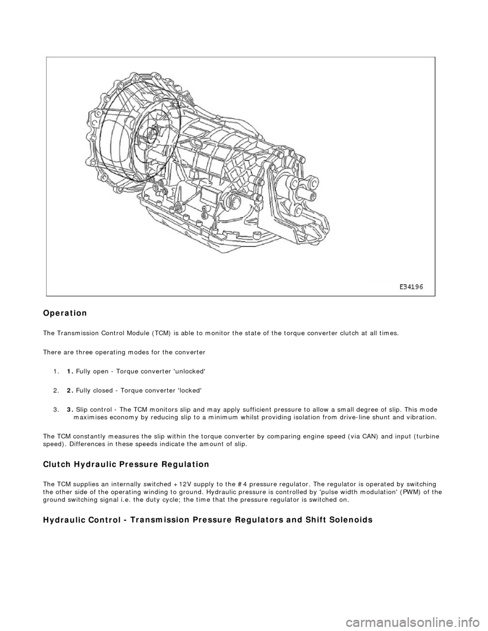
The T
ransmission Control Module (TCM) is
able to monitor the state of the torque converter clut ch at all times.
There are three operating modes for the converter
1. 1. Fully open - Torque converter 'unlocked'
2. 2. Fully closed - Torque converter 'locked'
3. 3. Slip control - The TCM monitors slip and may apply sufficie nt pressure to allow a small degree of slip. This mode
maximises economy by reducing slip to a minimum whilst providing isolation from drive-line shunt and vibration.
The TCM constantly measures the slip within the torque conver ter by comparing engine speed (via CAN) and input (turbine
speed). Differences in these speeds indicate the amount of slip.
Clutch Hydraulic Pressure Regulation
The T
CM supplies an internally switched +1
2V supply to the #4 pressure regulator. The regulator is operated by switching
the other side of the operating winding to ground. Hydraulic pressure is controlled by 'pulse width modulation' (PWM) of the
ground switching signal i.e. the duty cycle; the time that the pressure regulator is switched on.
Hydraulic Control
- Transmission Pre
ssure Regulators an d Shift Solenoids
Page 1264 of 2490
Opera
tion
F
l
uid flow within the transmission assembly is controlled
by three solenoid valves and five pressure regulators.
The TCM supplies an internally switched +12V supply to each sh ift solenoid and pressure regulator. Hydraulic pressure from
the pressure regulators is controlled by 'pulse width modulation' (PWM) of the ground switching signal i.e. the duty cycle;
the time that the pressure regu lator is switched on. Control of the solenoids is effected by switching one side to ground
through the TCM.
During normal operation the TCM monitors 'Switch On' of the so lenoids, regulators and the TCM output stages, but does not
check output stage 'Switch Off'.
It e
m
Par
t
Number
De
scr
iption
1—Shif
t Sole
noid #3
2—Shif
t Sole
noid #2
3—Shif
t Sole
noid #1
4—Pressure R
e
gulator #5
5—Pressure R
e
gulator #4
6—Pressure R
e
gulator #3
7—Pressure R
e
gulator #2
8—Pressure R
e
gulator #1
Page 1265 of 2490
Voltage is monitored at the regulators and solenoids for continuity and shorts. For example, when a solenoid is ON the
voltage on the TCM side should be ground , when OFF the voltage should be +12.
Shift Solenoid
The function of the three soleno id valves is to control the flow of transmissi on oil to the various transmission components.
Three solenoid valves are located wi thin the transmission assembly, and are closed when not energized.
Pressure Regulator
The function of the five pressu re regulators is to modulate the oil pressure to the various transmission components. The
regulators are pulse width modulated by the TCM, switching to ground potential. The other side of the regulators being
connected, via an internal TCM relay, to battery voltage. The regulator is closed when not energized by the TCM.
Transmission Fluid Temperature Sensor
Page 1270 of 2490

1.1. The hydraulic system has 'fail-safe' characteristics regardin g its electrical operation, such that should the power
supply be lost to the electro-hydraulic actuators the transmission will initiate a limp-home mode.
2. 2. Recognition of critical shift operation by monitoring the last element in the signal path, ie the solenoid valve, and
checking by means of redundant me asured variables, ie engine speed, input speed and output speed.
3. 3. Each time the vehicle is started there is a check on the entire safety hardware and the associated program parts
and signal paths. A malfunction in this part of the system, or triggering of the safety circuit, is communicated to
the operator through the illumination of the transmission warning lamp.
TCM Inputs
Input Speed Sensor (Torque Converter Turbine)
The input speed sensor provides the TCM with transmission inpu t shaft speed information. This signal is produced from an
inductive pick-up, generating 30 pulses per revolution.
Transmission Output Speed Sensor
The output speed sensor provides the TCM with transmission ou tput shaft speed information. This signal is produced from
an inductive pick-up, generati ng 36 pulses per revolution.
Transmission Oil Temperature Sensor
A thermistor which provides an electrical indication of the oi l temperature to the TCM. The signal is measured as a voltage
with reference to analog ue ground in the TCM.
Kickdown Switch (where fitted)
Kickdown is intended to provide maximum vehicle acceleration , via the appropriate downshift(s), when the operator uses
full throttle. A kickdown switch provides an electrical signal to the TCM wh en the accelerator pedal is fully pressed. The
switch is normally open, connected to vehicle ground. Should the switch fail the TCM will detect kickdown using the
accelerator pedal position.
Throttle Pedal Stop (where fitted)
This component, used where the kickdown switch is not fitted, limits throttle pedal travel .in the same way. The kickdown
feature is retained, but is controlled by throttle position only. The pedal stop must be set, using the PDU, in the same way
as the kickdown switch to optimize performance.
Mode Selection Switch
The mode selection switch is a two position switch indicati ng to the TCM the current performance mode selected by the
driver. The switch generates a tw o-bit digital input to the TCM.
Rotary Position Switch
The rotary position switch detects the position of the transmis sion selector shaft. The switch is supplied as part of a new
transmission assembly, mounted on the transmission body. The swit ch is used to indicate to the TCM the six positions of the shaft: Park, Reverse, Neutral, Drive, Third and Second. The switch provides a four-bit input to the TCM.
Drive to Fourth Switch
Detects the movement of the selector lever from Drive to Fourth position. The selector cable, and therefore the transmission selector shaft, does not move as the lever is operated between these two positions. The switch is located within the 'J-gate'
assembly, producing a digital output to indicate to the TCM that the lever has moved from D to 4 .
Serial Communications Interfaces
Page 1272 of 2490

3.3. Gradient: Under specific speeds and loads
4. 4. Cruise: During cruise control
5. 5. Manual: Shift map when the LH side of the 'J gate' is used
Three specific condition shift maps have a higher priority than the two base shift maps and will intervene when appropriate
conditions prevail for traction, gradient or cruise.
When traction control (engine or brake system derived) is operational the TCM will implement the traction map to maximise
control of wheel slip.
The gradient maps are intended to enhance vehicle drivability when towing or climbing a gradient. The TCM will implement
the maps when increased driving resistan ce is detected and enhanced drivability, cooling and increa sed performance is
appropriate.
The cruise map is intended to minimize unwanted gearshifts and 'hunting' and is activated when cruising near to the set
speed, or resuming.
Connector Pins Identification
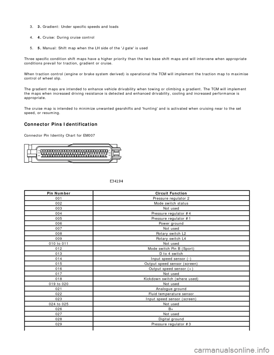
Connector Pin Identity Chart for EM007
Pin NumberCircuit Function
001Pressure regulator 2
002Mode switch status
003Not used
004Pressure regulator #4
005Pressure regulator #1
006Power ground
007Not used
008Rotary switch L2
009Rotary switch L4
010 to 011Not used
012Mode switch Pin B (Sport)
013D to 4 switch
014Input speed sensor (-)
015Output speed sensor (screen)
016Output speed sensor (+)
017Not used
018Kickdown switch (where used)
019 to 020Not used
021Analogue ground
022Fluid temperature sensor
023Input speed sensor (screen)
024 to 025Not used
026B+
027Not used
028Digital ground
029Pressure regulator #3
Page 1273 of 2490
Connector Pin Identity Chart for CC014
Connector Pin Identity Chart for EM047
030Shift solenoid valve #1
031Not used
032Shift solenoid valve #3
033Shift solenoid valve #2
034Power ground
035Not used
036Rotary switch L1
037Rotary switch L3
038 to 041Not used
042Input speed sensor (+)
043Not used
044Output speed sensor (-)
045Mode switch Pin A (Normal)
046 to 050Not used
051Pressure regulator #5
053Solenoid valve (+)
052Pressure regulator (+)
054Fused ignition (+)
055Fused ignition (+)
056 to 081Not used
082CAN link In (-)
083CAN link In (+)
084Not used
085CAN link Out (-)
086CAN link Out (+)
087JDS L-line (not used)
088JDS K-line (not used)
Pin NumberCircuit Function
112V ignition
2Security LED (power)
3CAN link In (-)
4CAN link In (+)
5Gate illumination (power)
6Security LED (ground)
7Not used
8CAN link Out (-)
9CAN link Out (+)
10Gate illumination (ground)
11Not used
12Not used