1998 JAGUAR X308 brake
[x] Cancel search: brakePage 1137 of 2490
Intake Air Distribution and Filtering - Throt
tle Body Elbow4.0L NA V8 -
AJ27/3.2L NA V8 - AJ26
Re
moval and Installation
Remov
al
S
pecial Tool(s)
Re
lease tool - quick fit
310-044 (JD 182)
R
elease tool 5 /16 - quick fit
310-054 (JD 203)
1. WARNING: BEFORE PROCEEDING, IT IS ESSENTIAL THAT
THE WARNING NOTES GIVEN IN SECTION 100-00 (UNDER THE
HEADING 'SAFETY PRECAUTIONS') ARE READ AND
UNDERSTOOD.
Disconnect battery ground cable (IMPORTANT, see SRO
86.15.19 for further information).
2. D
epressurize fuel sy
stem; refer to 19.50.02
3. Remove air cleaner cover / intake assembly; refer to 19.10.30.
4. Remove throttle body; refer to 19.70.04.
5. R
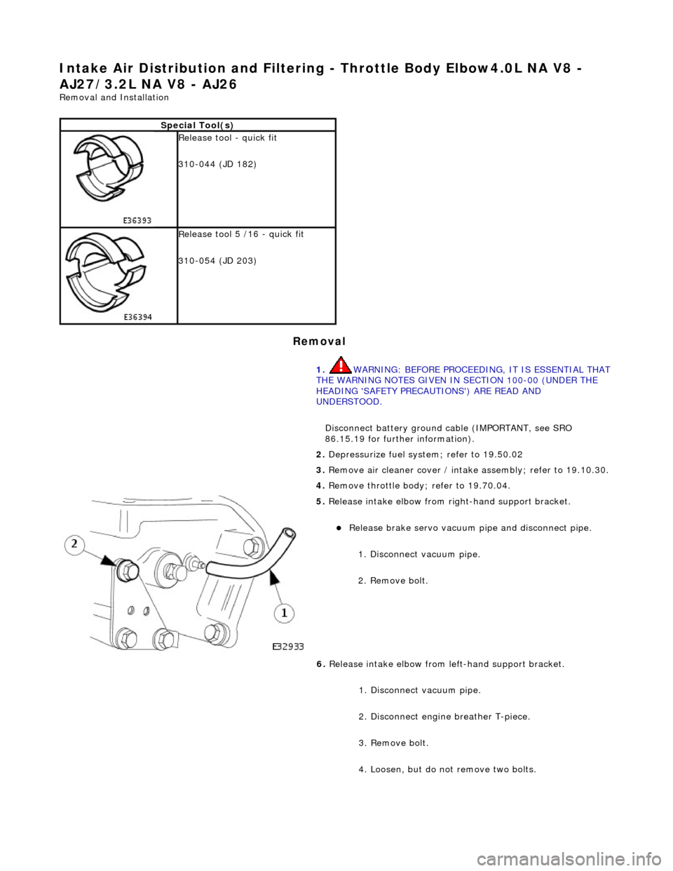
elease intake elbow from right-hand support bracket.
Re
lease brake servo vacuum pi
pe and disconnect pipe.
1. Disconnect vacuum pipe.
2. Remove bolt.
6. Release intake elbow from le ft-hand support bracket.
1. Disconnect vacuum pipe.
2. Disconnect engine breather T-piece.
3. Remove bolt.
4. Loosen, but do not remove two bolts.
Page 1142 of 2490
Intake Air Distribution and Filtering - Throttle B
ody Elbow4.0L SC V8 -
AJ26
Re mo
val and Installation
Remova
l
1.
WARNING: BE
FORE PROCEEDING, IT IS ESSENTIAL THAT
WARNING NOTES GIVEN IN SECTION 100-00 (UNDER HEADING
'SAFETY PRECAUTIONS') AR E READ AND UNDERSTOOD.
Disconnect battery ground cable (IMPORTANT, see SRO
86.15.19 for further information).
2. Re
move air cleaner cover / inta
ke assembly; refer 19.10.30.
3. Remove throttle assemb ly; refer to 19.70.04.
4. Remove exhaust gas recirculation (EGR) valve where installed;
refer 17.45.01.
5. Re
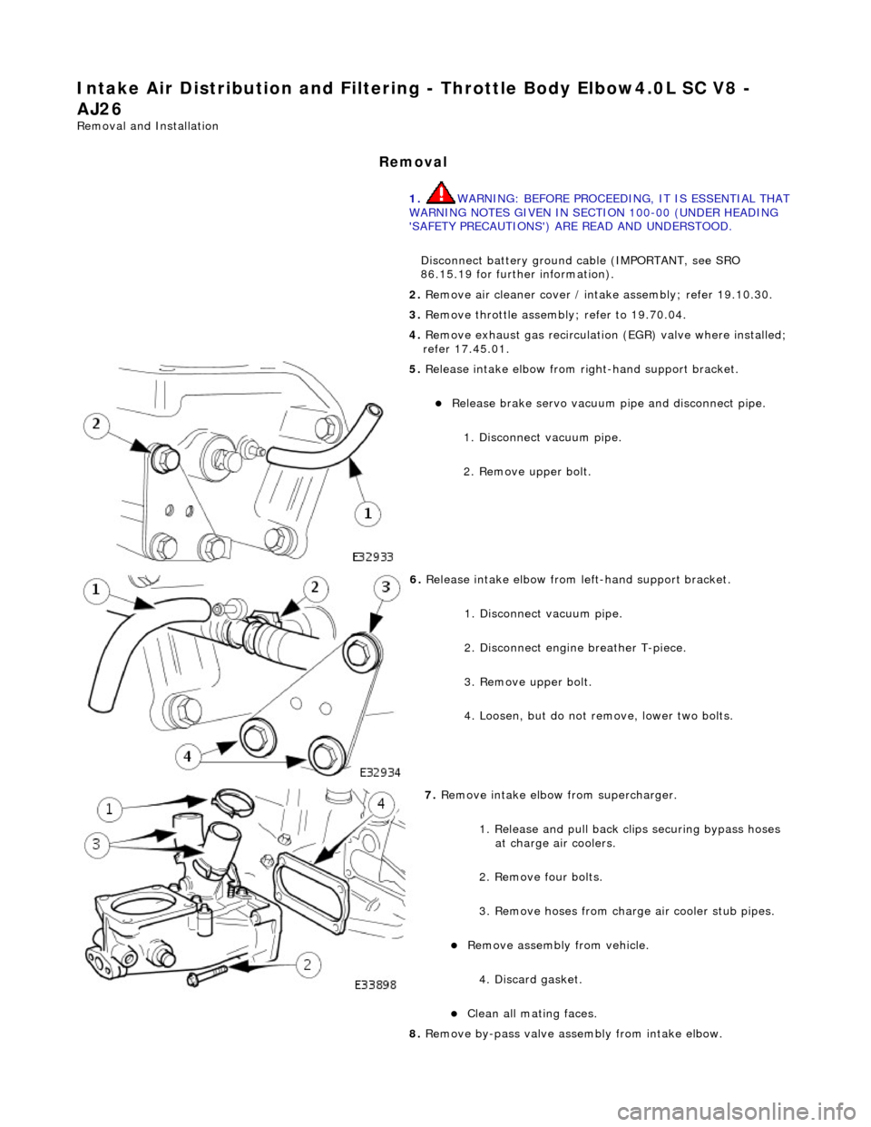
lease intake elbow from right-hand support bracket.
Re
lea
se brake servo vacuum pi
pe and disconnect pipe.
1. Disconnect vacuum pipe.
2. Remove upper bolt.
6. Relea
se intake elbow from le
ft-hand support bracket.
1. Disconnect vacuum pipe.
2. Disconnect engine breather T-piece.
3. Remove upper bolt.
4. Loosen, but do not remove, lower two bolts.
7. Re
move intake elbow from supercharger.
1. Release and pull back cl ips securing bypass hoses
at charge air coolers.
2. Remove four bolts.
3. Remove hoses from charge air cooler stub pipes.
Re move as
sembly from vehicle.
4. Discard gasket.
Cle a
n all mating faces.
8. Remove by-pass valve assembly from intake elbow.
Page 1206 of 2490
or sho
rt circuit to B+ voltage
Ignition modul
e
2 ground circuit
fault
Ignition coil relay fai
lure
Ignition coil
open/short
circuit
Ignition modul
e
2 failure
P1474Int
e
rcooler coolant pump relay
malfunction
Intercooler pump relay failure
Intercooler pump relay
to ECM
drive circuit fault
Intercooler pump relay coi
l ground
circuit fault
ECM power supply f
ault
F
or i
ntercooler pump relay circuit
tests,GO to Pinpoint Test Z.
.
P1475Ra
diator fans slow
(series) circuit
malfunction
R a
diator fan control relay module
to ECM 'series' drive circuit (relay
pin 9) fault
Relay coil ignition power supply
o p
en circuit
ECM ground circuit fault (relay coil
drive)
ECT se ns
or circuit malfunction
(refer to P0116)
F o
r radiator fan seri
es circuit tests,GO
to Pinpoint Test AA.
P1476Ra
diator fans fast (parallel) circuit
malfunction
R a
diator fan control relay module
to ECM 'parallel' drive circuit (relay
pin 7) fault
Relay coil ignition power supply
o p
en circuit
ECM ground circuit faul
t (relay coil
drive)
ECT sens
or circuit malfunction
(refer to P0116)
F or radi
ator fan parallel circuit
tests,GO to Pinpoint Test AB.
.
P1516Gear change PARK
/NEUTRAL
driving malfunction
Transmission range (T
R) sensor to
ECM circuit open circuit or high
resistance
TR sensor f
ailure
D-
4
switch to TCM circuit open
circuit or high resistance
D-4 swi
tch fault
For
PARK/NEUTRAL tests,GO to
Pinpoint Test AC.
.
P1517Engine PA
RK/NEUTRAL
cranking
malfunction
Transmissi on range (T
R) sensor to
ECM circuit open circuit or high
resistance
TR sensor f
ailure
Fo
r
PARK/NEUTRAL tests,GO to
Pinpoint Test AC.
.
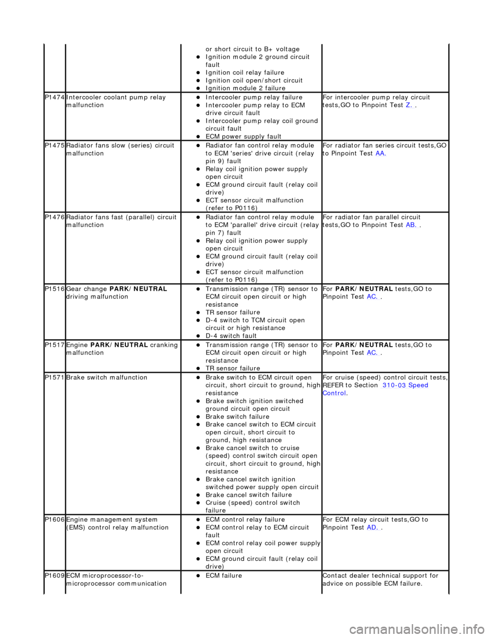
P1571Brake swit
ch malfunction
Brake sw
it
ch to ECM circuit open
circuit, short circ uit to ground, high
resistance
Brake sw it
ch ignition switched
ground circuit open circuit
Brake sw it
ch failure
Brake ca
ncel
switch to ECM circuit
open circuit, short circuit to
ground, high resistance
Brake ca nce
l switch to cruise
(speed) control switch circuit open
circuit, short circ uit to ground, high
resistance
Brake cance
l switch ignition
switched power supply open circuit
Brake ca nce
l switch failure
Cru
i
se (speed) control switch
failure
For cru i
se (speed) control circuit tests,
REF
E
R to Section 310
-03
Sp
eed
Control.
P1606Engine
m
anagement system
(EMS) control relay malfunction
ECM co ntrol rel
ay failure
ECM c
o
ntrol relay to ECM circuit
fault
ECM co ntrol rel
ay coil power supply
open circuit
ECM ground circuit faul t (relay coil
drive)
F or ECM
relay circuit tests,GO to
Pinpoint Test AD.
.
P1609EC
M microprocessor-to-
microprocessor communication
ECM failu r
e
Contact deal
er techni
cal support for
advice on possible ECM failure.
Page 1272 of 2490
3.3. Gradient: Under specific speeds and loads
4. 4. Cruise: During cruise control
5. 5. Manual: Shift map when the LH side of the 'J gate' is used
Three specific condition shift maps have a higher priority than the two base shift maps and will intervene when appropriate
conditions prevail for traction, gradient or cruise.
When traction control (engine or brake system derived) is operational the TCM will implement the traction map to maximise
control of wheel slip.
The gradient maps are intended to enhance vehicle drivability when towing or climbing a gradient. The TCM will implement
the maps when increased driving resistan ce is detected and enhanced drivability, cooling and increa sed performance is
appropriate.
The cruise map is intended to minimize unwanted gearshifts and 'hunting' and is activated when cruising near to the set
speed, or resuming.
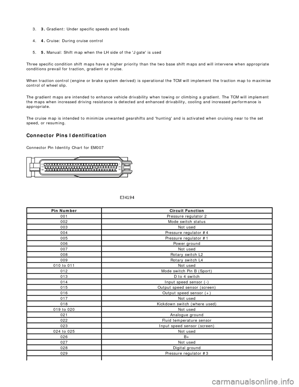
Connector Pins Identification
Connector Pin Identity Chart for EM007
Pin NumberCircuit Function
001Pressure regulator 2
002Mode switch status
003Not used
004Pressure regulator #4
005Pressure regulator #1
006Power ground
007Not used
008Rotary switch L2
009Rotary switch L4
010 to 011Not used
012Mode switch Pin B (Sport)
013D to 4 switch
014Input speed sensor (-)
015Output speed sensor (screen)
016Output speed sensor (+)
017Not used
018Kickdown switch (where used)
019 to 020Not used
021Analogue ground
022Fluid temperature sensor
023Input speed sensor (screen)
024 to 025Not used
026B+
027Not used
028Digital ground
029Pressure regulator #3
Page 1390 of 2490
Stator, intermediate and output shafts. Three epicyclic geartrains. Six multi-disc clutch/brake packs. Two freewheels (One-way clutches). Hydraulic pump. Parking lock assembly. Electro-hydraulic control unit. Internal harness and 13 pin connector with bayonet lock.
Hydraulic pump
This engine driven pump is located at the front of the transmission casing and provides pressure for the hydraulic
functions.
Supplies fluid under pressure to the torq ue converter, geartrain, electro-hydraulic control unit and the lubrication
circuit.
Draws fluid from the fluid pa n below the transmission casing, through a filter.
Parking lock
This component prevents movement of th e vehicle by engaging a fixed pawl with the parking lock gear located on the
output shaft. The pawl is engaged by movi ng the gear selector lever to the park (P) position.
Electro-hydraulic control unit
This unit, mounted in the transmission lower case, converts signals, mechanical from the J-gate and electrical from the
TCM, into hydraulic functions.
The following components ar e assembled to the unit:
Selector valve. Shift plate. Control valve - modulating pressure. Control valve - shift pressure. Solenoid valve 1 <-> 2 and 4 <-> 5 shift. Solenoid valve 3 <-> 4 shift. Solenoid valve 2 <-> 3 shift. Solenoid valve - converter lock-up. Speed sensors (2). Temperature sensor.
Speed sensors
There are two speed sensors within the transmission assembly which provide input to the TCM. These inputs, when used in
conjunction with CAN data relative to engine speed (from ECM) and road speed (from ABS), are used to electronically
control the transmission.
Temperature sensor
The output from this sensor allows the TCM to compensate for the affect of fluid temperature on shift time and quality
Control Systems
Hydraulic Control
The selector valve is operated directly by the J-gate and directs fluid flow for P R N D.
Of the four solenoid valves, 3 control shifts and 1 controls converter lock-up. One control valve controls modulating pressure
and the other shift pressure.
Regulating valves are used to maintain/control pressure for lu brication, normal operating functions, and the supply to the
control valves and shift valves.
Page 1394 of 2490
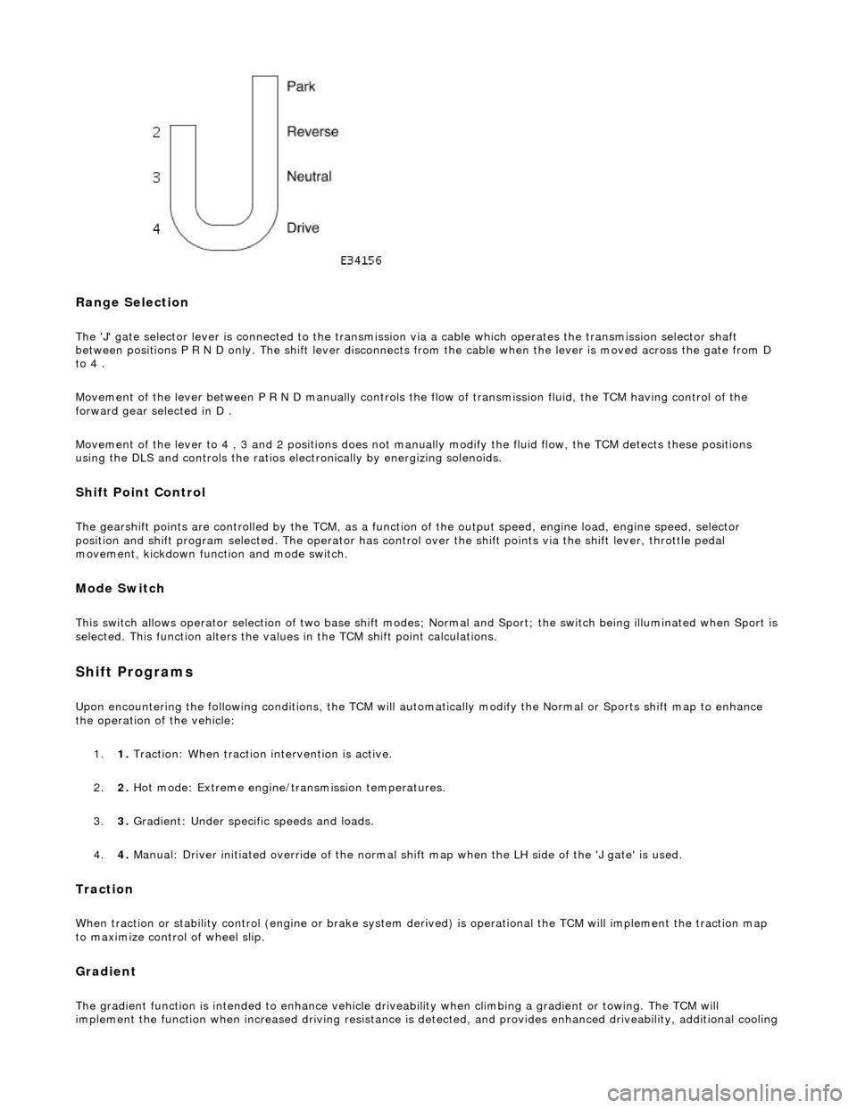
Range Selection
The 'J' gate selector lever is connected to the transmission via a cable which operates the transmission selector shaft
between positions P R N D only. The shift lever disconnects from the cable when the lever is moved across the gate from D
to 4 .
Movement of the lever between P R N D manu ally controls the flow of transmission fluid, the TCM having control of the
forward gear selected in D .
Movement of the lever to 4 , 3 and 2 positions does not manu ally modify the fluid flow, the TCM detects these positions
using the DLS and controls the ratios electronically by energizing solenoids.
Shift Point Control
The gearshift points are controlled by the TCM, as a function of the output speed, engine load, engine speed, selector
position and shift program selected. The operator has control over the shift points via the shift lever, throttle pedal
movement, kickdown function and mode switch.
Mode Switch
This switch allows operator selection of two base shift modes; Normal and Sport; th e switch being illuminated when Sport is
selected. This function alters the values in the TCM shift point calculations.
Shift Programs
Upon encountering the following conditions, the TCM will auto matically modify the Normal or Sports shift map to enhance
the operation of the vehicle:
1. 1. Traction: When traction intervention is active.
2. 2. Hot mode: Extreme engine/transmission temperatures.
3. 3. Gradient: Under specific speeds and loads.
4. 4. Manual: Driver initiated override of the normal shif t map when the LH side of the 'J gate' is used.
Traction
When traction or stability control (engine or brake system de rived) is operational the TCM will implement the traction map
to maximize control of wheel slip.
Gradient
The gradient function is intended to enhance vehicle drivea bility when climbing a gradient or towing. The TCM will
implement the function when increased driving resistance is de tected, and provides enhanced driveability, additional cooling
Page 1465 of 2490
The Drive-to-fourth switch:
Detects when the gear selector lever is moved from Drive to Fourth. Is hard-wired to the transmission control module.
The Neutral position switch:
Is hard-wired to the body processor module. Detects when the gear selector lever is moved to the Neutral position.
The Park position switch:
Is hard-wired to the body processor module. Detects when the gear selector leve r is moved to the Park position.
The gear selector module:
Provides illumination of the gear sele ctor surround, which is dimmable via a CA N signal from the instrument cluster. Provides red illumination, on the gear selector surround, of the gear selected, by CAN signals from the instrument
cluster.
Illuminates the security system Active LED on the gear se lector surround, in response to an input from the body
processor module.
Is connected to the fascia harness via a 12-way connector. Refer to Connec tor Pins Identification, 307-01A.
The gear selector interlock solenoid:
Prevents the gear selector lever from be ing moved from the Park position, unless th e ignition switch is in position II,
and the brake pedal is depressed.
Is controlled by an input from the body processor module.
The seven gear selector positions are:
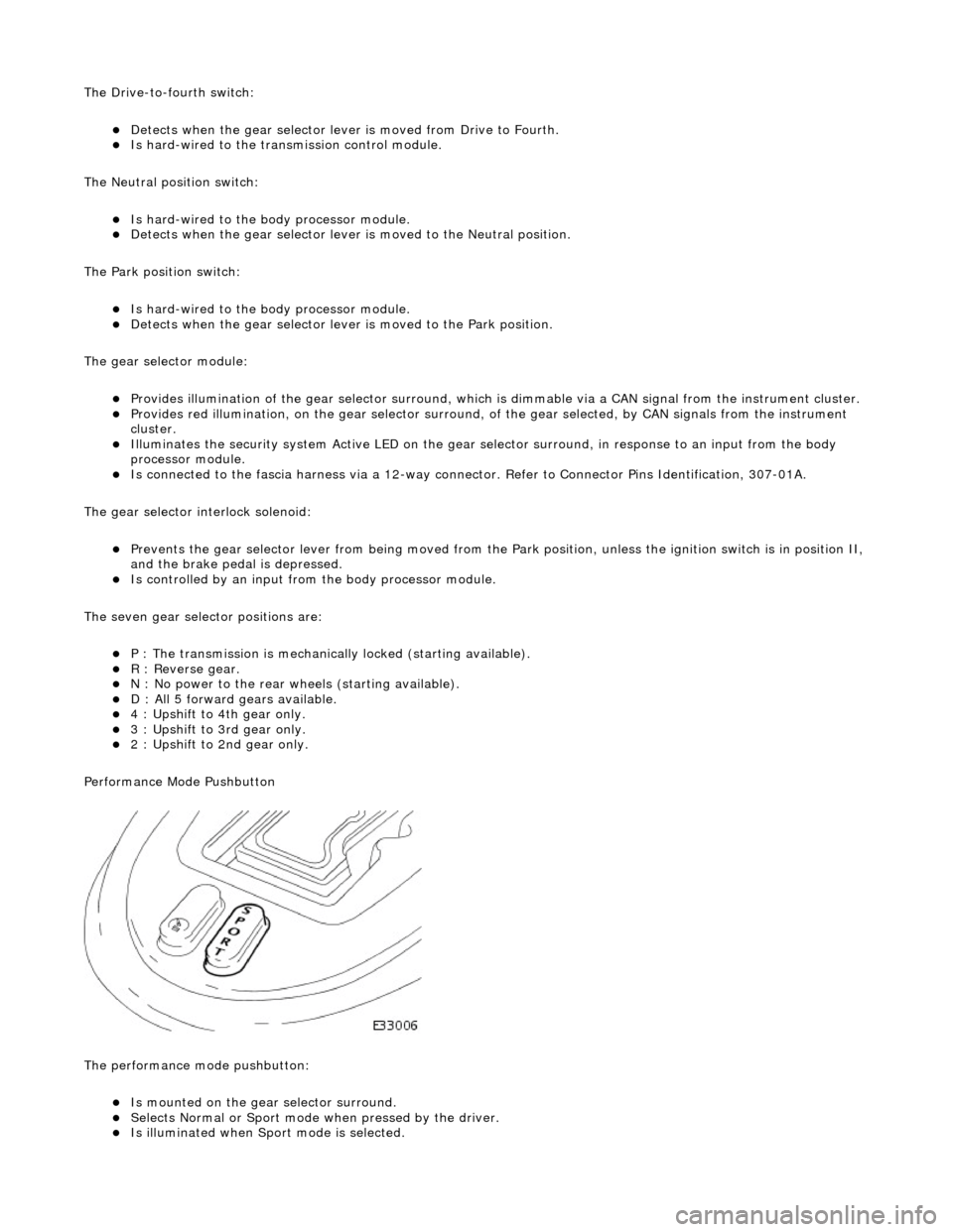
P : The transmission is mechanically locked (starting available). R : Reverse gear. N : No power to the rear wh eels (starting available). D : All 5 forward gears available. 4 : Upshift to 4th gear only. 3 : Upshift to 3rd gear only. 2 : Upshift to 2nd gear only.
Performance Mode Pushbutton
The performance mode pushbutton:
Is mounted on the gear selector surround. Selects Normal or Sport mode when pressed by the driver. Is illuminated when Sport mode is selected.
Page 1478 of 2490
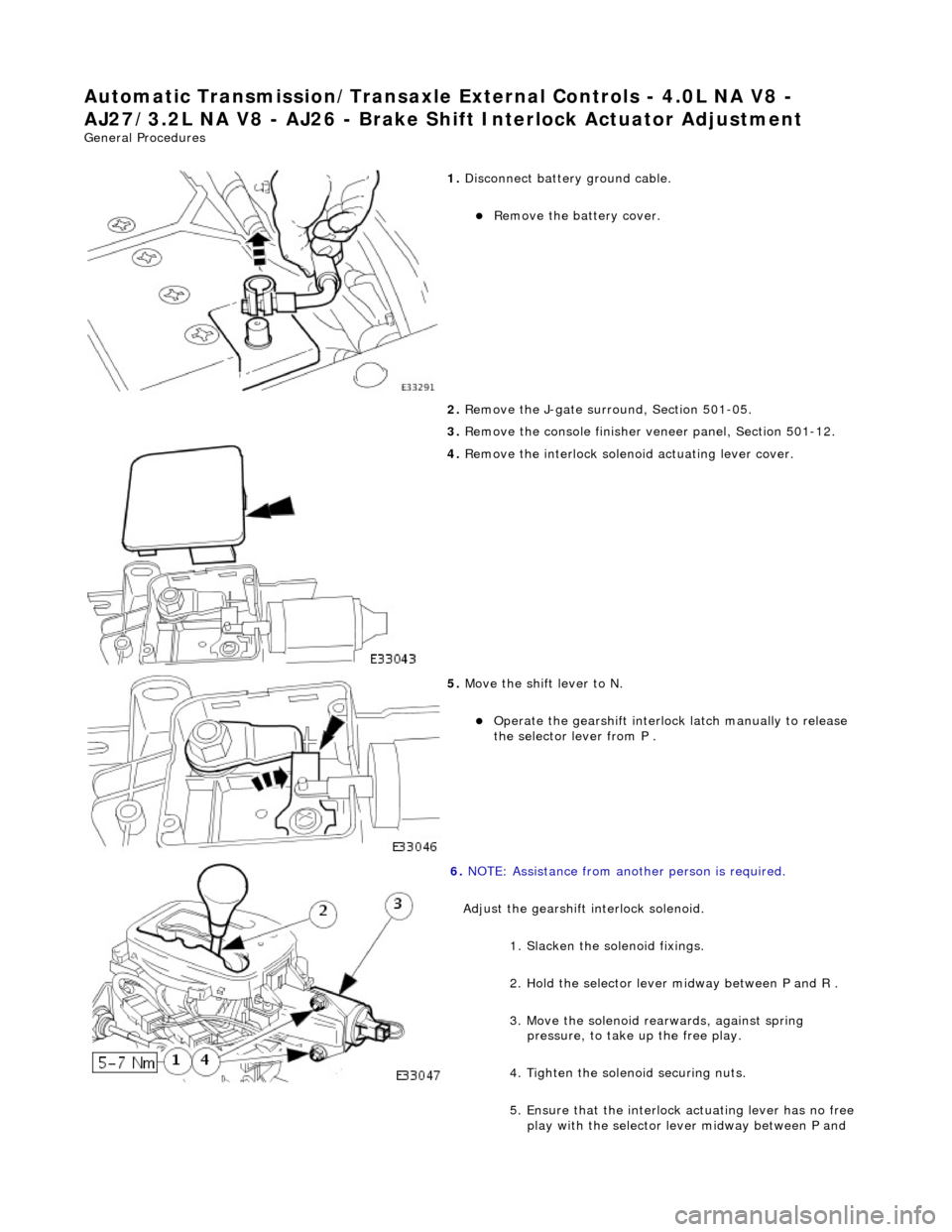
Automatic Transmission/Transaxle External Controls - 4.0L NA V8 -
AJ27/3.2L NA V8 - AJ26 - Brake Shift Interlock Actuator Adjustment
General Procedures
1. Disconnect battery ground cable.
Remove the battery cover.
2. Remove the J-gate surround, Section 501-05.
3. Remove the console finisher ve neer panel, Section 501-12.
4. Remove the interlock soleno id actuating lever cover.
5. Move the shift lever to N.
Operate the gearshift interlock latch manually to release
the selector lever from P .
6. NOTE: Assistance from anot her person is required.
Adjust the gearshift interlock solenoid. 1. Slacken the solenoid fixings.
2. Hold the selector lever midway between P and R .
3. Move the solenoid rearwards, against spring pressure, to take up the free play.
4. Tighten the soleno id securing nuts.
5. Ensure that the interloc k actuating lever has no free
play with the selector lever midway between P and