1998 JAGUAR X308 brake
[x] Cancel search: brakePage 1480 of 2490
Automatic Transmission/Transaxle External Controls - 4.0L NA V8 -
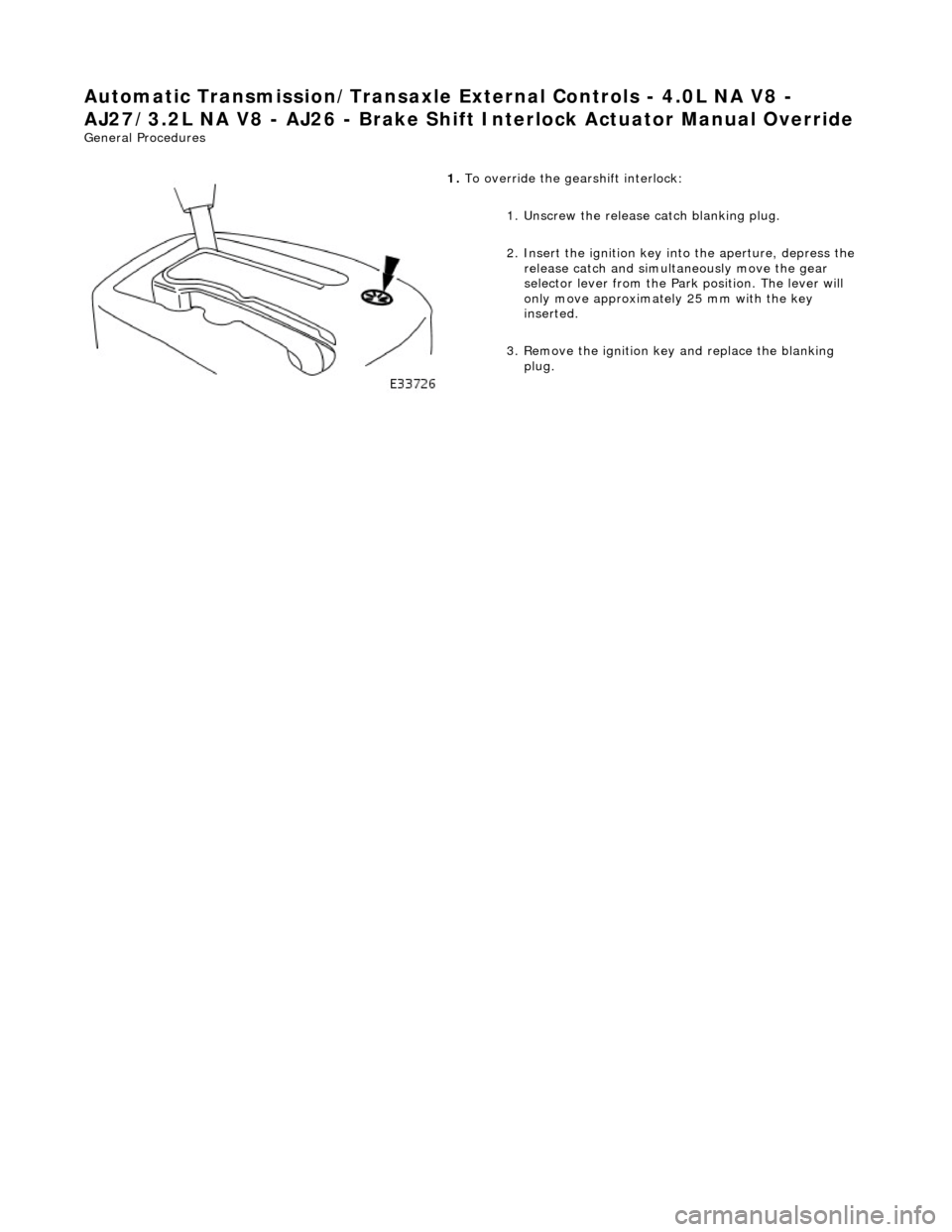
AJ27/3.2L NA V8 - AJ26 - Brake Shift Interlock Ac tuator Manual Override
General Procedures
1. To override the gearshift interlock:
1. Unscrew the release catch blanking plug.
2. Insert the ignition key into the aperture, depress the release catch and simultan eously move the gear
selector lever from the Park position. The lever will
only move approximately 25 mm with the key
inserted.
3. Remove the ignition key and replace the blanking plug.
Page 1501 of 2490
Selector lever:
Gear selector positions are:
P Transmission mechanically locked, starting available * R Reverse gear N Neutral gear, no power to the rear wheels (starting available) D Drive gear, all 5 forward gears available (see Performance Mode Pushbutton) 4 Upshift to 4th gear only 3 Upshift to 3rd gear only 2 Upshift to 2nd gear only
Gearshift Interlock Manual Override*
The interlock system which locks the sele ctor in P and prevents the ignition key from being removed except when P is
selected, may be manually overridden in the event of an emergency.
1. 1. With the parking brake applied
2. 2. Remove the access blank using a suitable Torx bit
3. 3. Insert a small screwdriver into the vacated hole
4. 4. Push the screwdriver downwards, gently, and hold whilst simultaneously moving the selector from P towards R ,
but do not engage R until the tool has been removed
5. 5. An audible warning may be heard when operation 4 is carried out
6. 6. With the selector in N and the access bl ank replaced, the vehicle may be started
Range Selection
The selector lever transmits operator demand to the transmission and TCM by means of a cable and Dual-Linear
Switch (DLS).
The lever operates the transmission assemb ly selector shaft, only for P R N D , by means of a cable. Movement of the
lever across the gate to 4, 3 and 2 positions disengages th e cable from the selector lever and engages the DLS which
controls gear selection electronically.
Gear selector module:
Provides illumination of the decal relevant to the gear sele cted. This information is provided by CAN from the TCM. Illuminates the security system Active LED on the gear selector surround, in response to an output from the BPM.
Transmission Switches
Performance Mode Pushbutton
7—Connector - Climate control
8—Solenoid - Gear selector
9—Security system Active LED
Page 1502 of 2490
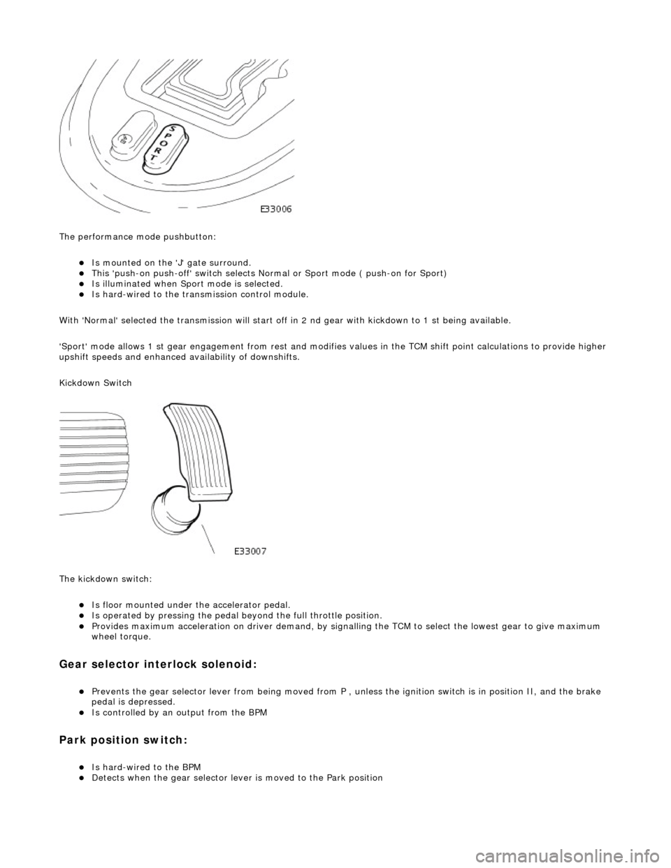
The performance mode pushbutton:
Is mounted on the 'J' gate surround. This 'push-on push-off' swit ch selects Normal or Sport mode ( push-on for Sport) Is illuminated when Sport mode is selected. Is hard-wired to the transmission control module.
With 'Normal' selected the transmissi on will start off in 2 nd gear with kickdown to 1 st being available.
'Sport' mode allows 1 st gear en gagement from rest and modifies values in the TCM shift point calculations to provide higher
upshift speeds and enhanced availability of downshifts.
Kickdown Switch
The kickdown switch:
Is floor mounted under th e accelerator pedal. Is operated by pressing the pedal beyond the full throttle position. Provides maximum acceleration on driver demand, by signalling the TCM to select the lowest gear to give maximum
wheel torque.
Gear selector interlock solenoid:
Prevents the gear selector lever from being moved from P , unless the ignition switch is in position II, and the brake
pedal is depressed.
Is controlled by an output from the BPM
Park position switch:
Is hard-wired to the BPM Detects when the gear selector lever is moved to the Park position
Page 1504 of 2490
Automatic Transmission/Transaxle External Controls - 4.0L SC V8 - AJ26 -
External Controls
Diagnosis and Testing
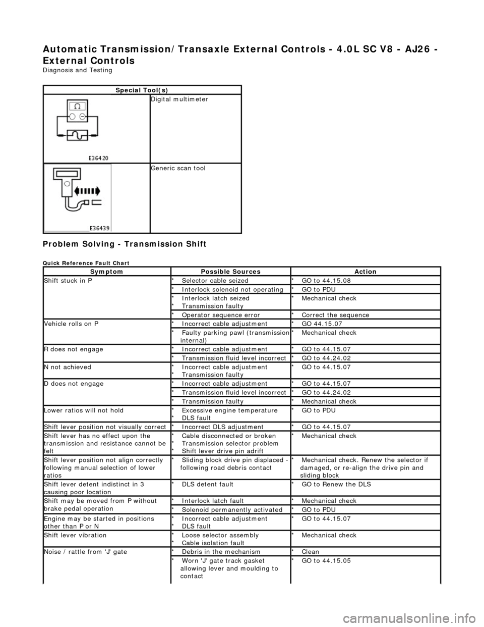
Problem Solving - Transmission Shift
Quick Reference Fault Chart
Special Tool(s)
Digital multimeter
Generic scan tool
SymptomPossible SourcesAction
Shift stuck in P Selector cable seized
*GO to 44.15.08
*
Interlock solenoid not operating
*GO to PDU
*
Interlock latch seized
Transmission faulty
*
*Mechanical check
*
Operator sequence error
*Correct the sequence
*
Vehicle rolls on P Incorrect cable adjustment
*GO 44.15.07
*
Faulty parking pawl (transmission internal)
*Mechanical check
*
R does not engageIncorrect cable adjustment
*GO to 44.15.07
*
Transmission fluid level incorrect
*GO to 44.24.02
*
N not achievedIncorrect cable adjustment
Transmission faulty
*
*GO to 44.15.07
*
D does not engageIncorrect cable adjustment *GO to 44.15.07
*
Transmission fluid level incorrect
*GO to 44.24.02
*
Transmission faulty
*Mechanical check
*
Lower ratios will not holdExcessive engine temperature
DLS fault
*
*GO to PDU
*
Shift lever position not visually correctIncorrect DLS adjustment
*GO to 44.15.07
*
Shift lever has no effect upon the
transmission and resistance cannot be
feltCable disconnected or broken
Transmission selector problem
Shift lever drive pin adrift
*
*
*Mechanical check
*
Shift lever position not align correctly
following manual selection of lower
ratiosSliding block drive pin displaced - following road debris contact
*Mechanical check. Renew the selector if
damaged, or re-align the drive pin and
sliding block
*
Shift lever detent indistinct in 3
causing poor locationDLS detent fault
*GO to Renew the DLS
*
Shift may be moved from P without
brake pedal operationInterlock latch fault
*Mechanical check
*
Solenoid permanently activated
*GO to PDU
*
Engine may be started in positions
other than P or N Incorrect cable adjustment
DLS fault
*
*GO to 44.15.07
*
Shift lever vibrationLoose selector assembly
Cable isolation fault
*
*Mechanical check
*
Noise / rattle from 'J' gateDebris in the mechanism
*Clean
*
Worn 'J' gate track gasket
allowing lever and moulding to
contact
*GO to 44.15.05
*
Page 1508 of 2490
Automatic Transmission/Transaxle External Contro ls - 4.0L SC V8 - AJ26 -
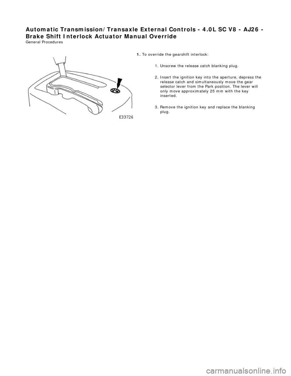
Brake Shift Interlock Actuator Manual Override
General Procedures
1. To override the gearshift interlock:
1. Unscrew the release catch blanking plug.
2. Insert the ignition key into the aperture, depress the release catch and simultan eously move the gear
selector lever from the Park position. The lever will
only move approximately 25 mm with the key
inserted.
3. Remove the ignition key and replace the blanking plug.
Page 1511 of 2490
Automatic Transmission/Transaxle External Contro ls - 4.0L SC V8 - AJ26 -
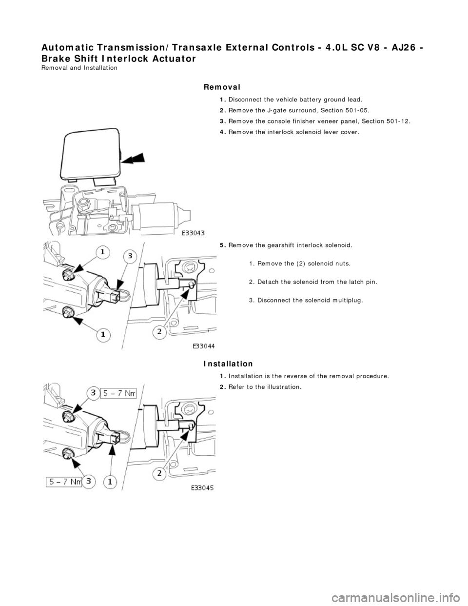
Brake Shift Interlock Actuator
Removal and Installation
Removal
Installation
1.
Disconnect the vehicle battery ground lead.
2. Remove the J-gate surround, Section 501-05.
3. Remove the console finisher ve neer panel, Section 501-12.
4. Remove the interlock so lenoid lever cover.
5. Remove the gearshift interlock solenoid.
1. Remove the (2) solenoid nuts.
2. Detach the solenoid from the latch pin.
3. Disconnect the solenoid multiplug.
1. Installation is th e reverse of the re moval procedure.
2. Refer to the illustration.
Page 1689 of 2490
Fuel System - General Information - Fuel System Pre
ssure Check
Gen
eral Procedures
WARNING: Working on the fuel system re sults in fuel and fuel vapor being present in the atmosphere. Fuel vapor is
extremely flammable, hence great care must be taken whilst working on the fuel system. Adhere strictly to the following
precautions:
D
o not smoke in the work area
Di
splay
NO SMOKING signs around the work area
D
isconnect the battery before
working on the fuel system
Av
oid sparks
Make sure sui
table fire ex
tinguishers are at hand
Make sure absor
bent material is at
hand to soak up any spillage
Make sure the work area is
well ventilated
M
ake sure that the gauge is correctly conn
ected, and that all connections are secure BEFORE starting the engine
DO N
OT
disconnect the gauge from the schrader valve while the engine is running
Make su
re the schrader valve reseals once the gauge is disconnected
• NOTE: Depending on the design of the ga uge set, there may be a drain valve and tube. Make sure this valve is closed, and
the drain tube placed in a suitable container BEFORE connecting the gauge to the schrader valve.
1. Make sure the vehi
cle is in
Park for vehicles with automatic
transmission, Neutral for vehicles with manual transmission.
2. Apply the parking brake.
3. Place suitable absorbent material around the schrader valve to
absorb any spillage when connecting the gauge set.
4. Remove the protective cap from the schrader valve.
5. Connect the gauge, using adaptors if required.
6. Remove the absorbent material and dispose of safely.
7. Disconnect and plug the vacuum hose from the pressure
regulator.
8. Start the engine and record the fuel pressure reading.
As a gui
de, the fuel pressu
re should be approximately 3.0
bar (44.1 psi) with the regulator disconnected.
9. With the engine still running, reconnect the vacuum hose to
the pressure regulator an d record the reading.
Th
e pressure should dr
op to approximately 2.6 bar (38
psi) when the vacuum hose is reconnected.
10. Switch off the engine.
11. Place more absorbent material around the schrader valve.
12. Where fitted, open the drain valve and allow the fuel from the
gauge and line to flow into the container to depressurize the
system.
13. Disconnect and remove the gauge set and any adaptors.
14. Clean up any fuel which may have been spilt and remove the
absorbent material. Dispose of safely.
15. Refit and secure the protective cap to the schrader valve.
16. Reconnect the fuel pressure regulator vacuum hose.
17. Start the engine and make sure there are no leaks.
Page 1744 of 2490
Speed Control - Speed
Control
D
iagn
osis and Testing
Pri
n
ciples of operation
The s
p
eed (cruise) control sy
stem is activated by an ON/OFF master switch in the J-gate surround, which has an integral
LED to indicate status.
The steering wheel switches allow the driver to set the speed, increase or decrease the selected speed, cancel and resume
the facility without his/her hand ever leaving the steering wheel
The vehicle speed can be increased an d decreased in increments of 2 kmh (1 mph) by briefly pressing the + or - buttons up
to a maximum of five times.
Alternatively, the + or - button can be held until th e desired speed is reached.
The selected speed (by whichever method) w ill be displayed in the message center.
The system will not function at speeds below 26 kmh (16 mph), and can be cancelled from the master switch, the steering
wheel switches, and by depressing th e brake pedal. The system can be overridden by accelerating as normal.
In
spection and Verification
1.
1. Veri fy the customer concern.
2. 2. Vis
ually inspect for obvious signs of mechanical or electrical damage.
3. 3. If an obvious cause for an observed or reported concern is found, correct the cause (if possible) before proceeding
to the next step.
4. 4. If the cause is not visually evident, verify the symptom, check for DTCs and follow the routines in this section.
Vi
sual Inspection Chart
Diagnostic Trouble Code (D
TC) index
MechanicalElectrical
Throttle body mechan
ism
Throttle body actuator
Module Switch(es) Instrument cluster
DTC
De
scr
iption
Possib
l
e Source
Acti
o
n
P0566Speed
c
ontrol
CANCEL
switch ON fault
Speed
control switches internal steering wheel
short circuit to ground
St
eering wheel cassette reel short circuit to
ground
Cassette reel to ECM circ
uit short circuit to
ground
CANCEL
switch failure (stuck ON)
Fo
r
CANCEL switch circuit
tests,GO to Pinpoint Test A.
P0567Speed c
ontrol
RESUME
switch ON fault
Speed
control switches internal steering wheel
short circuit to ground
St
eering wheel cassette reel short circuit to
ground
Cassette reel to ECM circ
uit short circuit to
ground
RESUME swit
ch failure (stuck ON)
For
RESUME switch circuit
tests,GO to Pinpoint Test B.
P0568Spee
d control switch
ground malfunction
Speed
control switches internal steering wheel
open circuit
St
eering wheel cassette reel open circuit or
high resistance
Cassette reel to ECM ci
rcuit open circuit or high
For
ACCEL/DECEL switch circuit
tests,GO to Pinpoint Test C.