Page 2086 of 2490
Interior Trim and Ornamentation - Parcel Shelf
Removal and Installation
Removal
Installation
1.
Open both rear doors.
2. Remove rear seat cushion. Refer to 76.70.37.
3. Remove rear seat squa b. Refer to 76.70.38.
4. Remove and discard the two fir tr ee fasteners securing front of
tray to parcel shelf.
5. Remove parcel tray.
Slightly raise front of shelf trim and lift rear fold clear of
body flange.
Exercising care to avoid dama ging sun blind (if fitted) and
rear quarter trims, or dislodging high level stop lamp, slide trim from shelf, twist slightly and remove from vehicle via
rear doors.
1. Exercising care to avoid damaging sun blind (if fitted) and rear
quarter trims, or dislodging hi gh level stop lamp, slide trim
onto shelf, engaging rear fold on body flange.
2. Secure front of trim to shelf using two new fir tr ee fasteners.
3. Fit rear seat squab. Refer to 76.70.38.
4. Fit rear seat cushion. Refer to 76.70.37.
Page 2092 of 2490
6. Lift casing clear of door wais t flange and lock button and
withdraw for access.
7. Disconnect speaker, puddle lamp and switchpack harness
multiplugs.
8. Remove armrest lower securing clip housing from casing. and
refit to door.
9. Remove door inner waist seal from holder.
Slacken and remove screws securing waist seal holder
and remove seal holder.
10. Remove armrest from casing. Refer to 76.34.23.
11. Slacken and remove puddle la mp securing screws and
remove lamp assembly from casing.
Page 2093 of 2490
Installation
12. Remove pocket from door casing.
1. Release puddle lamp harness from clips at base of door pocket.
2. Slacken and remove th e two screws securing
bottom of pocket to casing.
3. Remove two spring clips securing top of pocket to casing.
13. Lift pocket from casing
14. Slacken and remove door sp eaker securing screws and
remove speaker from casing.
15. Remove speakere grill from casing
16. Remove casing to to door securing clips.
1. Fit and fully seat casing securing clips.
2. Position speaker grill in casing align speaker and fit and tighten
securing screws.
3. Position pocket in casing and secure with screws and spring
clips.
4. Fit puddle lamp to casing, fit and tighten securing screws and
position harness in pocket clips.
5. Fit door armrest to casing. Refer to 76.34.23.
6. Fit inner waist seal holder to casing and fit and tighten the six
securing screws.
7. CAUTION: Before installing door casing, ensure that
Page 2094 of 2490
primary water shedder is undamag
ed and correctly attached to
door inner panel.
Align and fit inner waist seal.
8. Check that armrest tang locater and screw insert are correctly
positioned in door panel.
9. Position casing for access and connect speaker, puddle lamp
and switchpack harnesses.
10. Finally position casing locating fold over waist flange and
firmly press armrest to locate retaining tang in door panel.
11. Commencing at front , press and firmly seat casing lower
fasteners in door inserts
12. Fit and tighten armrest centre se curing screw in door insert.
13. Fit door veneer panel. Refer to 76.47.12.
14. Position door handle escutche on on casing, fit and tighten
securing screw and fit cover over screw.
Page 2099 of 2490

Exterior Trim and Ornamentation - Exterior Trim
Description and Operation
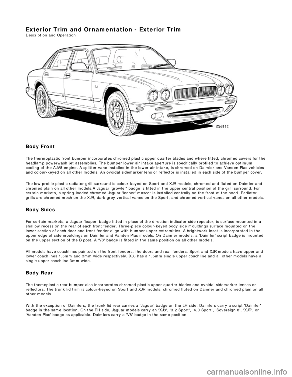
Body Front
The thermoplastic front bumper incorporates chromed plastic upper quarter blades and where fitted, chromed covers for the headlamp powerwash jet assemblie s. The bumper lower air intake aperture is specifically profiled to achieve optimum
cooling of the AJV8 engine. A splitter vane installed in the lowe r air intake, is chromed on Daimler and Vanden Plas vehicles
and colour-keyed on all other models. An ov oidal sidemarker lens or reflector is installed in each side of the bumper cover.
The low profile plastic radiator grill surround is colour-keyed on Sport and XJR mo dels, chromed and fluted on Daimler and
chromed plain on all other models .A Jaguar 'growler' badge is fitted in the upper central positi on of the grill surround. For
certain markets, a spring-loaded chromed Ja guar 'leaper' mascot is installed centrally on the front of the hood. Radiator
grills are chromed mesh on the XJR, dark grey vertical vanes on the Sport, and chromed ve rtical vanes on all other models.
Body Sides
For certain markets, a Jaguar 'l eaper' badge fitted in place of the direction indicator side re peater, is surface mounted in a
shallow recess on the rear of each fro nt fender. Three-piece colour-keyed body side mouldings surface mounted on the
lower section of each door and front fender align with bumper upper extremities. A brightwork inset is incorporated in the
upper edge of side mouldings on Daimler and Vanden Plas models. On Daimler models, a 'Daimler' script badge is mounted
on the upper section of the B post. A 'V8' badge is fitted in the same position on all other models.
All models have coachlines painted on th e front fenders, the doors and rear fender s. Sport and XJR models have upper and
lower coachlines 1.5mm an d 3mm wide respectively, XJ8 has a 1.5mm single upper coachline and all other models have a
single upper coachline 3mm wide.
Body Rear
The themoplastic rear bumper also inco rporates chromed plastic upper quarter blades and ovoi dal sidemarker lenses or
reflectors. The trunk lid trim is colour-keyed on Sport and XJ R models, chromed fluted on Daimler and chromed plain on all
other models.
With the exception of Daimlers, the trunk lid rear carries a 'Jaguar' badge on the LH side. Daimlers carry a script 'Daimler'
badge in the same location. On th e RH side, Jaguar models carry an 'XJ8', '3.2 Sport', '4.0 Sport', 'Sovereign 8', 'XJR', or
'Vanden Plas' badge as applic able. Daimlers carry a 'V8' badge in the same position.
Page 2106 of 2490
Exterior Trim and Ornamentation - Luggage Comp artment Lid Moulding
Removal and Installation
Removal
1. Remove battery cover and disc onnect ground cable from
battery terminal. Refer to 86.15.19.
2. Disconnect and remove trunk lamp assemblies. Refer to
86.45.16.
3. Remove covers from trunk latc h finisher securing bolts,
slacken and remove bolts and remove finisher.
4. Remove and discard trunk li d liner rear fasteners and
position liner for access.
5. Free trunk lid release button harness from retaining clip and
disconnect multiplug.
6. NOTE: The pressed steel fasteners fitted to Jaguar models
should be discarded on removal.
Slacken and remove nuts/fasteners securing trim finisher to
trunk lid.
Page 2108 of 2490
4.
Fit and fully seat a new harn ess grommet in trunk lid.
5. NOTE: Fit new pressed steel fasteners on Jaguar models.
Align and fully seat trim finisher on trunk lid and fit and fully
tighten securing nuts/fasteners.
6. Connect release button harness multiplug and position harness
in retaining clip.
7. Position and fully seat trunk li d trim pad and secure with new
fir tree fasteners.
8. Fit finisher over trunk latch, fi t and tighten securing bolts and
fit bolt covers..
9. Fit trunk lamp assemblies. Refer to 86.45.16.
10. Connect ground cable to batt ery terminal and fit battery
cover. Refer to 86.15.15.
Page 2179 of 2490

Glass, Frames and Mechanisms - Glass, Frames and Mechanisms
Description and Operation
Fixed Glass
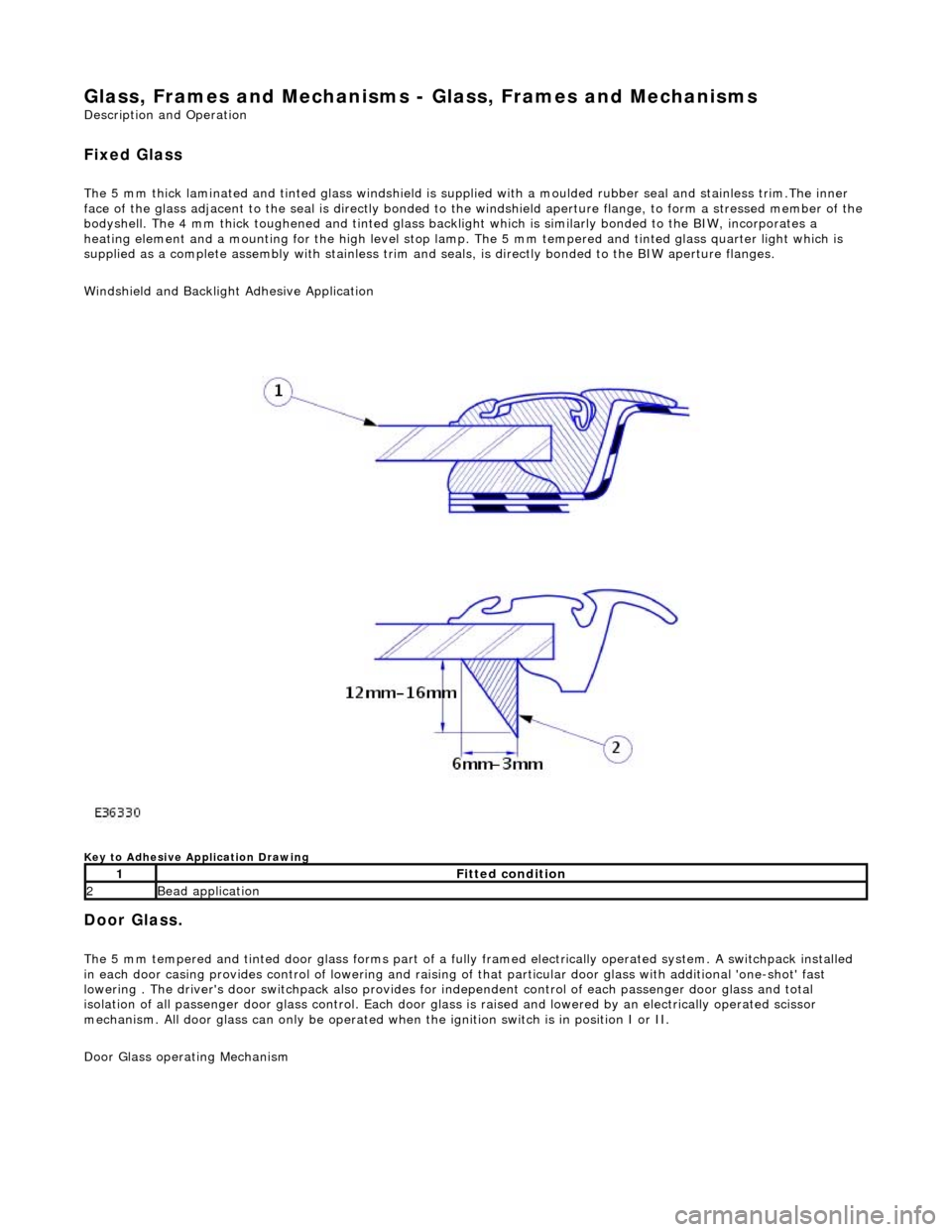
The 5 mm thick laminated and tinted glas s windshield is supplied with a moulded rubber seal and stainless trim.The inner
face of the glass adjacent to the seal is directly bonded to the windshield aperture flange, to form a stressed member of the
bodyshell. The 4 mm thick toughened and tinted glass backlight which is similarly bonded to the BIW, incorporates a
heating element and a mounting for the high level stop lamp. The 5 mm tempered and tinted glass quarter light which is
supplied as a complete assembly with stainless trim and seals, is directly bonded to the BIW aperture flanges.
Windshield and Backlight Adhesive Application
Key to Adhesive Application Drawing
Door Glass.
The 5 mm tempered and tinted door glass forms part of a fully framed electrically operated system. A switchpack installed
in each door casing provides control of lowering and raising of that particular d oor glass with additional 'one-shot' fast
lowering . The driver's door switchpack also provides for independent control of each passenger door glass and total
isolation of all passenger door glass control. Each door glas s is raised and lowered by an electrically operated scissor
mechanism. All door glass can only be operated wh en the ignition switch is in position I or II.
Door Glass operating Mechanism
1Fitted condition
2Bead application