Page 2054 of 2490

Interior Trim and Ornamentation - Interior Trim
Description and Operation
Carpets
The passenger compartment carpet is a one piece moulded constr uction with integral sound deadening material, heel mats
and driver's footrest. The carpet is attach ed to the vehicle floor by plastic clips fitted below the door treadplates. Removal of the carpet necessitates re moval of the front seats, lifting of the centre console rear extens ion and removal of the heelboard
carpet.
Fascia
The full width, slush moulded, soft feel PVC fascia is mounted on an injection moulded armature and is faced with wood
veneer. In addition to the air conditioning and central, outer and demisting vents, it accepts instrument packs dedicated to
market requirements and a centrally mounted analogue clock.
Doors
The one-piece door casings are trimmed in UEV to match the seating, with wood veneer at the waistline and a carpet insert
at the front lower corner. Each casing is secured to the door inner panel by fir tree press fast eners along the lower section,
two armrest fixings at the centre and vene er panel dowels and fixings at the top. The armrests which are common to front
and rear doors, are trimmed in matching leather or UEV according to specification. The door switchpacks, dedicated to
driver and front or rear passenger, are in corporated in the armrests. A speaker is in stalled in the lower section of each door
and a tweeter is incorporated behind each interior door handle escutcheon. Where premium ICE is fitted, the front tweeters
are installed in the upper A posts.
A, B, C and D Posts
On each side,a grained UEV finisher trimmed to match the headlining is secured to the 'A' post and cantrail by fir tree
fasteners locating in BIW apertures. The upper 'D' post finisher is trimmed and secured in the same manner. The single
piece'B/C' post finishers, also finished in grained matching UEV, each have a front se at belt exit aperture and are secured to
the BIW by four spring clips and two fir tree fasteners.
Headlining
The one-piece headlining consists of a 6mm thick polyurethane foam membrane covered with suede effect knitted polyester. The headlining is secured to the BIW roof by body tangs, the roof console, sun visors, combined grab handles and coat
hooks, the cantrail finishers and where fitt ed, the sliding roof finisher and clips.
Trunk
Carpet covered trims line the trunk and are secured by fir tr ee fasteners to the sides and front inner panel. The carpet
covered, two-section, removable trunk fl oor provides access to the spare wheel and wheel changing equipment, the battery
and electrical carrier. The floor board rests on the spare wheel, with the front and rear edges locating in blocks on the fuel
tank backboard and the rear of the body. The support blocks provide for two floor he ight settings to accommodate either a
space saver or full size spare wheel.A moulded finisher covering the rear of the trunk below the sill is secured to the rear
panel by tabs and fir tree fasteners. Finish er panels fitted to the rear lamp units provide trunk interior access to the lamps.
The trunk lid underside is fitted with a removabl e moulded liner and two trunk illumination lights.
Page 2273 of 2490

Handles, Locks, Latches and Entry Systems - Handles, Locks, Latches and
Entry Systems
Description and Operation
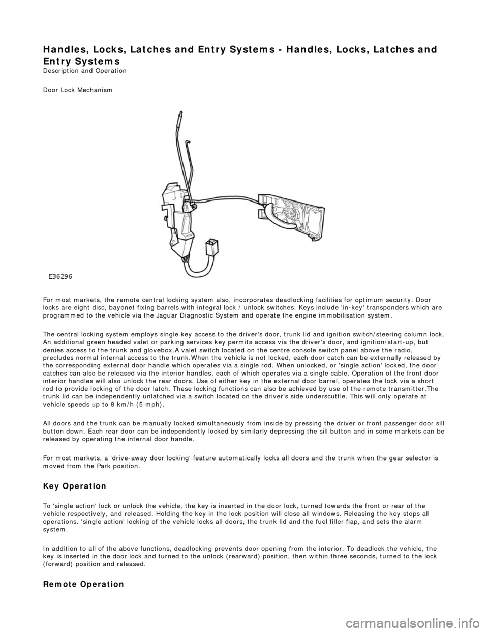
Door Lock Mechanism
For most markets, the remote central locking system also, in corporates deadlocking facilities for optimum security. Door
locks are eight disc, bayonet fixing barrels with integral lock / unlock switches. Keys include 'in-key' transponders which are
programmed to the vehicle via the Jaguar Diagnostic Sy stem and operate the engine immobilisation system.
The central locking system employs single key access to the driv er's door, trunk lid and ignition switch/steering column lock.
An additional green headed valet or park ing services key permits access via the driver's door, and ignition/start-up, but
denies access to the trunk and glovebox.A valet switch located on the centre console switch panel above the radio,
precludes normal internal access to the trunk.When the vehicle is not locked, each door catch can be externally released by
the corresponding external door handle which operates via a si ngle rod. When unlocked, or 'single action' locked, the door
catches can also be released via the interior handles, each of which operates via a single cable. Operation of the front door
interior handles will also unlock the rear doors. Use of either key in the external door barrel, operates the lock via a short
rod to provide locking of the door latch. These locking functions can also be achieved by use of the remote transmitter.The
trunk lid can be independently unlatched via a switch located on the driver's side underscuttle. This will only operate at
vehicle speeds up to 8 km/h (5 mph).
All doors and the trunk can be manually lock ed simultaneously from inside by pressing the driver or front passenger door sill
button down. Each rear door can be independently locked by si milarly depressing the sill button and in some markets can be released by operating the internal door handle.
For most markets, a 'drive-away door locking' feature automati cally locks all doors and the trunk when the gear selector is
moved from the Park position.
Key Operation
To 'single action' lock or unlock the vehicle, the key is inserted in the door lock , turned towards the front or rear of the
vehicle respectively, and released. Holding the key in the lock position will close all windows. Releasing the key stops all
operations. 'single action' locking of the vehicle locks all doors, the trunk lid and the fuel filler flap, and sets the alarm
system.
In addition to all of the above functions, deadlocking prevents door opening from th e interior. To deadlock the vehicle, the
key is inserted in the door lock and turned to the unlock (rearw ard) position, then within three seconds, turned to the lock
(forward) position and released.
Remote Operation
Page 2417 of 2490

Panels centered between two adjacent panels must have equal gaps on either side. For exceptions to this, refer to the
appropriate specification. Gaps between ad jacent panels or components must not expose harnesses, labels, brackets or
visually poor joint or assembly conditions.
• NOTE: Sliding roof panel clearances are specified without the edge seal installed.
Areas of particular concern are, fuel filler flap, trunk lid to fenders and saddle panels, hood to fenders, grill and headlamps,
sliding roof to main roof panel, door gaps at fenders, B\C posts, roof drip rail an d rocker panel, and bumper cover to fenders
and cross car assemblies
Alignment
Panels must be correctly profiled to maintain cosmetic appearance, and ensure co rrect seating of seals with minimal wind
noise. Areas of particular concern are hood to fenders, trunk lid to fenders and saddle panels, doors to apertures, doors to
fenders and adjacent doors and relationship of the sliding roof panel leading and trailing edges to the main roof panel.
Exterior Fitments
Bezels, trims and lamps must be concentric with apertu res and have equal clearances with adjacent panels.
Areas of particular concern are headlamp to hood, fender and trim panel, exhaust tailpipe trim to bumper cover cut-out,
rear lamp assembly to trunk lid, fender and bumper cover trim, and side feature lines including body side mouldings, fender
to door and door to door.
Exterior Clearances and Alignments-Front
Page 2481 of 2490
Uni-Body, Subframe and Mounting System - Rear Axle Crossmember
Removal and Installation
Removal
CAUTION: Replacement of nuts and bolts: Various thread-locking devices are used on nuts and bolts throughout the
vehicle. These devices restrict the number of times a nut or bolt can be used. See section 100-00 for information.
1. Raise vehicle on a four-post li ft. Refer to section 100-02.
2. Remove subframe to differentia l-casing rear bracket bolts.
3. Where fitted, remove bolts se curing fuel vapor pipe to
subframe.
4. Remove subframe to differential bracket front nuts and bolts.
5. Support the differential assembly.
Position a jack under the differential drive coupling.
Position a piece of wood between the jack and the
differential drive coupling.
Raise the jack until the diffe rential is just supported.
Page 2483 of 2490
Installation
11. Remove subframe from vehicle.
12. Clean relevant components and mating faces.
1. With assistance fit suspension subframe to vehicle.
Position subframe on vehi cle, ensuring that fuel
evaporation pipe is not trapped.
Install but do not tighten sub frame center to differential
casing bolts.
2. Install link assemblies to suspension subframe bolts
1. Ensure spacer is in position.
2. Install but do not tighten bolt.
Following the same procedure, in stall bolt on opposite side
of subframe.
3. Install but do not tighten subframe front to differential bracket
nuts and bolts
4. Install and tighten sub frame to differential rear bracket bolts to
88-118Nm.
Page 2484 of 2490
5. Tighten link assembly bolts to 88-118Nm.
6. Tighten subframe front to differential bracket nuts and bolts to
69-92Nm.
7. Where fitted, install fuel vapo r pipe to subframe bolts.
8. Tighten subframe center to di fferential casing bolts to 88-
118Nm.