Page 1721 of 2490
Wi
th BT009 disconnected, measure the resistance across
the fuel pump connectors reference BT009/003 and
BT009/004.
1
I
s the resistance < 5 OHM?
Yes GO to B11
No Renew the fuel pump and te st the system for normal
operation.
B11: CHECK FU
EL PUMP GROUND CONTINUITY
Page 1727 of 2490
Conne
ct the scan tool
1
Have the DTC(s) and fr
eeze
frame data been recorded?
Yes GO to C2
C2
: CHECK CONTINUITY FUEL SENSOR
W
ith connectors BT014 and BT015 disconnected check
the resistance between the fuel level sensor pins.
1
Is
the resistance >70 and <1000 OHM?
Yes GO to C3
No Renew the level sensor and test the system for normal
operation.
C3
: CHECK FOR SHORT TO GROUND
Page 1732 of 2490
Fu
el Tank and Lines - Fuel Level Sensor
Remov
a
l and Installation
Removal
Ins
tallation
1.
WA
RNING: BEFORE PROCEEDING, IT IS ESSENTIAL THAT THE
WARNING NOTES GIVEN IN SECTIO N 100-00 (UNDER THE HEADING
'SAFETY PRECAUTIONS') ARE READ AND UNDERSTOOD.
Remove the battery. For additional information, refer to Section 414
-01
Battery, Mounting and Cables
.
2.
Drain
the fuel tank using a suitable suction pump/tanker. If the On-
board Refueling Vapour Recovery (ORVR) system is fitted, refer to
Section 310
-00 Fu
el System
- Gen
e
ral Information
.
3. Remov
e the trunk front liner. For additional information, refer to
Section 501
-05 Interior Trim
and Ornamentation
.
4. D
isconnect the harness co
nnections to the sensor.
5. U
sing special tool 18G 1001, remo
ve the sensor retaining ring.
6.
Remov
e the sensor assembly and discard the seal.
1. Fitting a new level sensor is the reverse of the removal procedure,
noting that a new seal must be fitted.
Page 1733 of 2490

Fuel Tank and Li
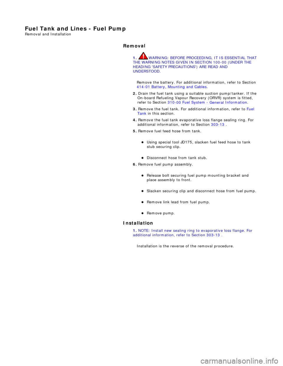
nes - Fuel Pump
Re
moval and Installation
Remov
al
Installation
1.
WARNING: B
EFORE PROCEEDING, IT IS ESSENTIAL THAT
THE WARNING NOTES GIVEN IN SECTION 100-00 (UNDER THE
HEADING 'SAFETY PRECAUTIONS') ARE READ AND
UNDERSTOOD.
Remove the battery. For additional information, refer to Section
414
-0
1 Battery, Mounting and Cables
.
2.
Drain th
e fuel tank using a suitab
le suction pump/tanker. If the
On-board Refueling Vapour Recove ry (ORVR) system is fitted,
refer to Section 310
-00
Fuel System
- General
Information
.
3. R
emove the fuel tank. For addi
tional information, refer to Fuel
Tank
in this section.
4. Remove the fuel tank evaporativ e loss flange sealing ring. For
additional information, refer to Section 303
-13
.
5. R
emove fuel feed hose from tank.
U
sing special tool JD175, slacken fuel feed hose to tank
stub securing clip.
Di
sconnect hose from tank stub.
6. Remove fuel pump assembly.
R
elease bolt securing fuel
pump mounting bracket and
place assembly to front.
Slac
ken securing clip and disc
onnect hose from fuel pump.
R
emove link lead from fuel pump.
Re
move pump.
1. NOTE: Install new sealing ring to evaporative loss flange. For
additional information, refer to Section 303
-13
.
In
stallation is th
e reverse of the removal procedure.
Page 1734 of 2490

Fuel Tank and Lines - Fuel Tank
Re
mo
val and Installation
Remov
a
l
•
NO
TE: This removal/installation procedure is applicable to all tank assembly variants.
S
p
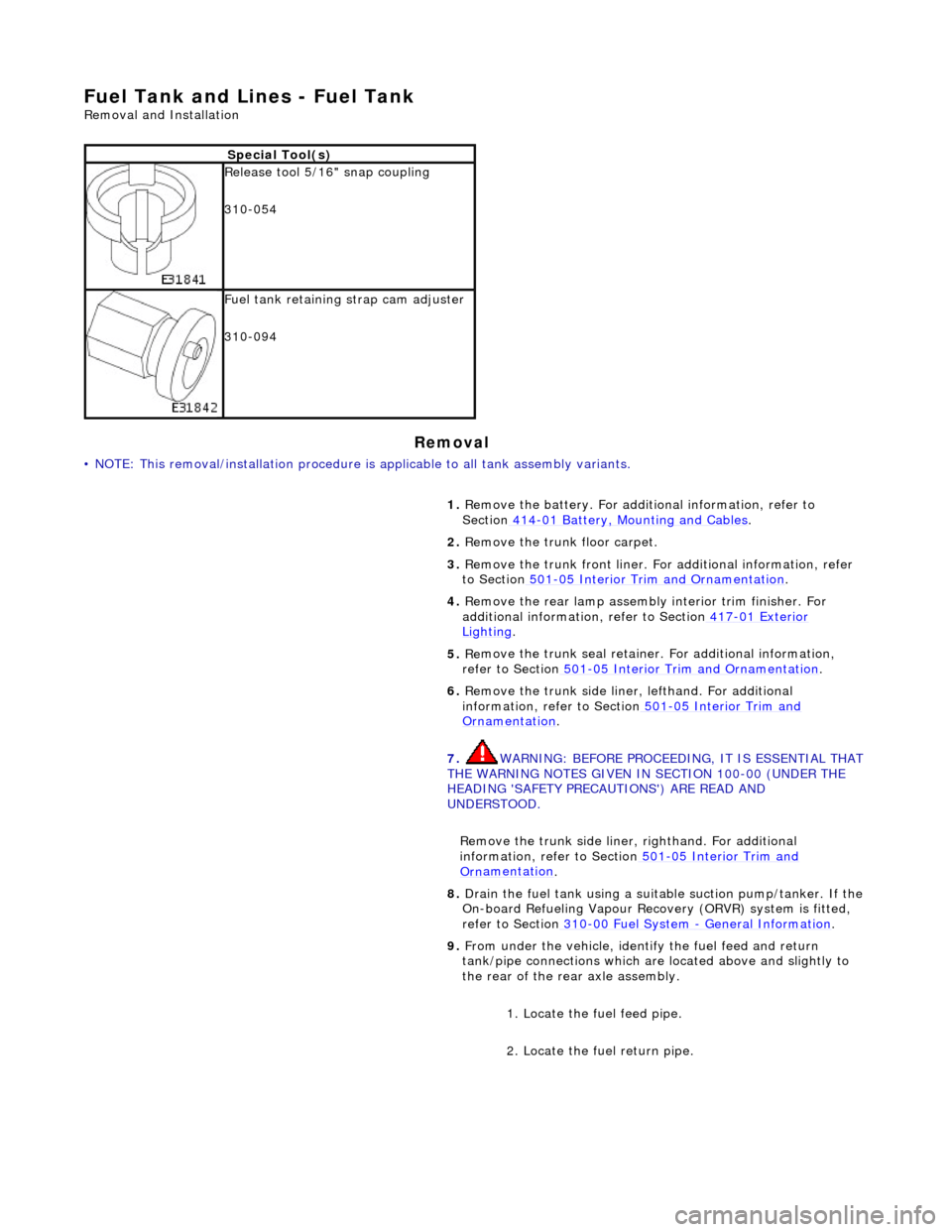
ecial Tool(s)
R
e
lease tool 5/16" snap coupling
310-054
F u
el tank retaining strap cam adjuster
310-094
1. Remove the battery. For additi onal information, refer to
Section 414
-01
Battery, Mounting and Cables
.
2. Re
move the trunk floor carpet.
3. Remove the trunk front liner. Fo r additional information, refer
to Section 501
-05
Interior Trim and Ornamentation
.
4. Re
move the rear lamp assembly interior trim finisher. For
additional information, refer to Section 417
-01
Exterior
Ligh
ting.
5. Re
move the trunk seal retainer
. For additional information,
refer to Section 501
-0 5
Interior Trim and Ornamentation
.
6. Re
move the trunk side liner, lefthand. For additional
information, refer to Section 501
-05
Interior Trim and
Or
n
amentation
.
7. WARNING: B E
FORE PROCEEDING, IT IS ESSENTIAL THAT
THE WARNING NOTES GIVEN IN SECTION 100-00 (UNDER THE
HEADING 'SAFETY PRECAUTIONS') ARE READ AND
UNDERSTOOD.
Remove the trunk side liner, righthand. For additional
information, refer to Section 501
-05
Interior Trim and
Or
n
amentation
.
8.
Drain th e fue
l tank using a suitab
le suction pump/tanker. If the
On-board Refueling Vapour Recove ry (ORVR) system is fitted,
refer to Section 310
-00 Fu
el System
- General
Information
.
9. Fr
om under the vehicle, identify the fuel feed and return
tank/pipe connections which are located above and slightly to
the rear of the rear axle assembly.
1. Locate the fuel feed pipe.
2. Locate the fuel return pipe.
Page 1735 of 2490

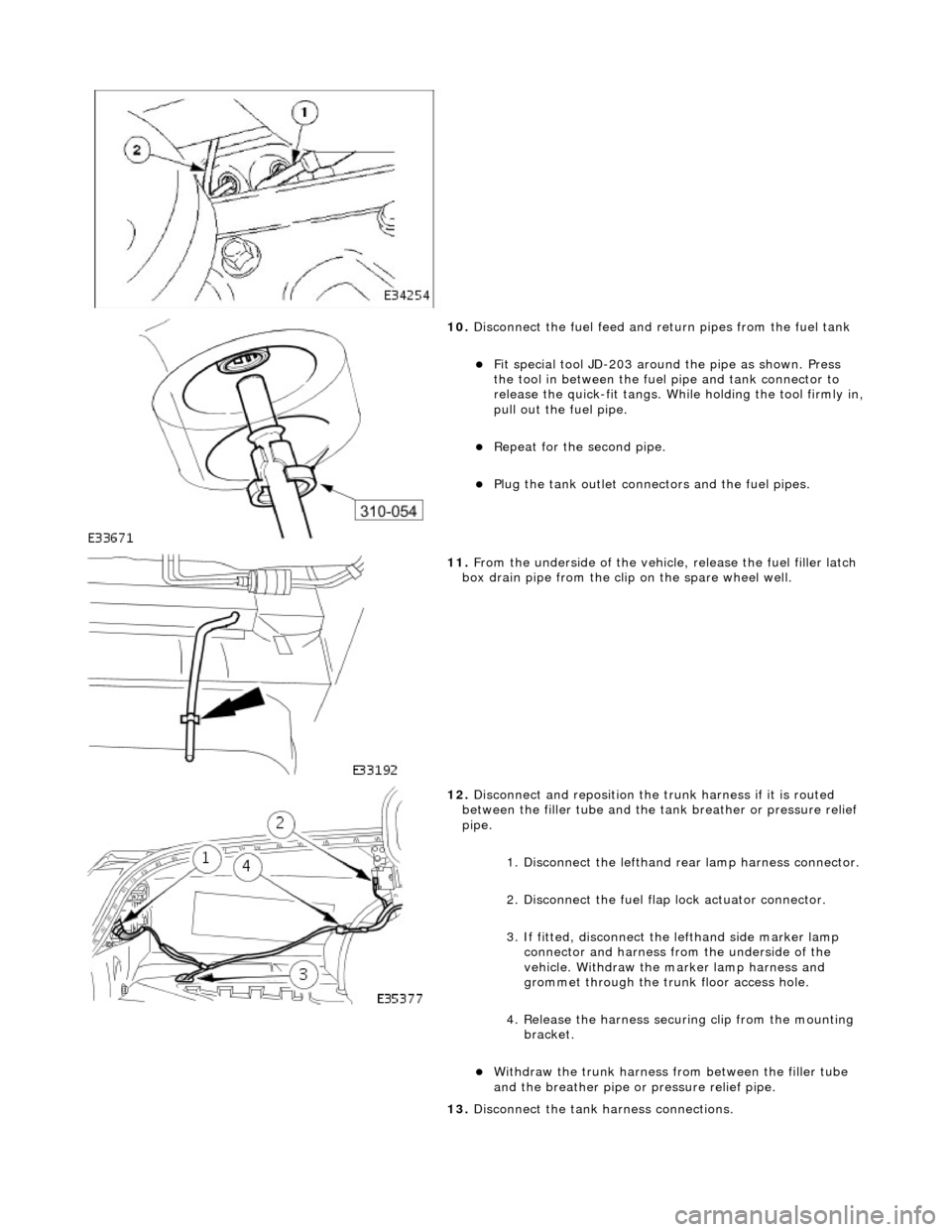
10
.
Disconnect the fuel feed and return pipes from the fuel tank
F
it special tool JD-203 around
the pipe as shown. Press
the tool in between the fuel pipe and tank connector to
release the quick-fit tangs. While holding the tool firmly in,
pull out the fuel pipe.
Repeat
for the second pipe.
Plu
g the tank outlet connectors and the fuel pipes.
11
.
From the underside of the vehicl e, release the fuel filler latch
box drain pipe from the clip on the spare wheel well.
12
.
Disconnect and reposition the tr unk harness if it is routed
between the filler tube and the ta nk breather or pressure relief
pipe.
1. Disconnect the lefthand re ar lamp harness connector.
2. Disconnect the fuel flap lock actuator connector.
3. If fitted, disconnect the lefthand side marker lamp
connector and harness fro m the underside of the
vehicle. Withdraw the marker lamp harness and
grommet through the trunk floor access hole.
4. Release the harness securi ng clip from the mounting
bracket.
Wi
thdraw the trunk harness from between the filler tube
and the breather pipe or pressure relief pipe.
13. Disconnect the tank harness connections.
Page 1736 of 2490

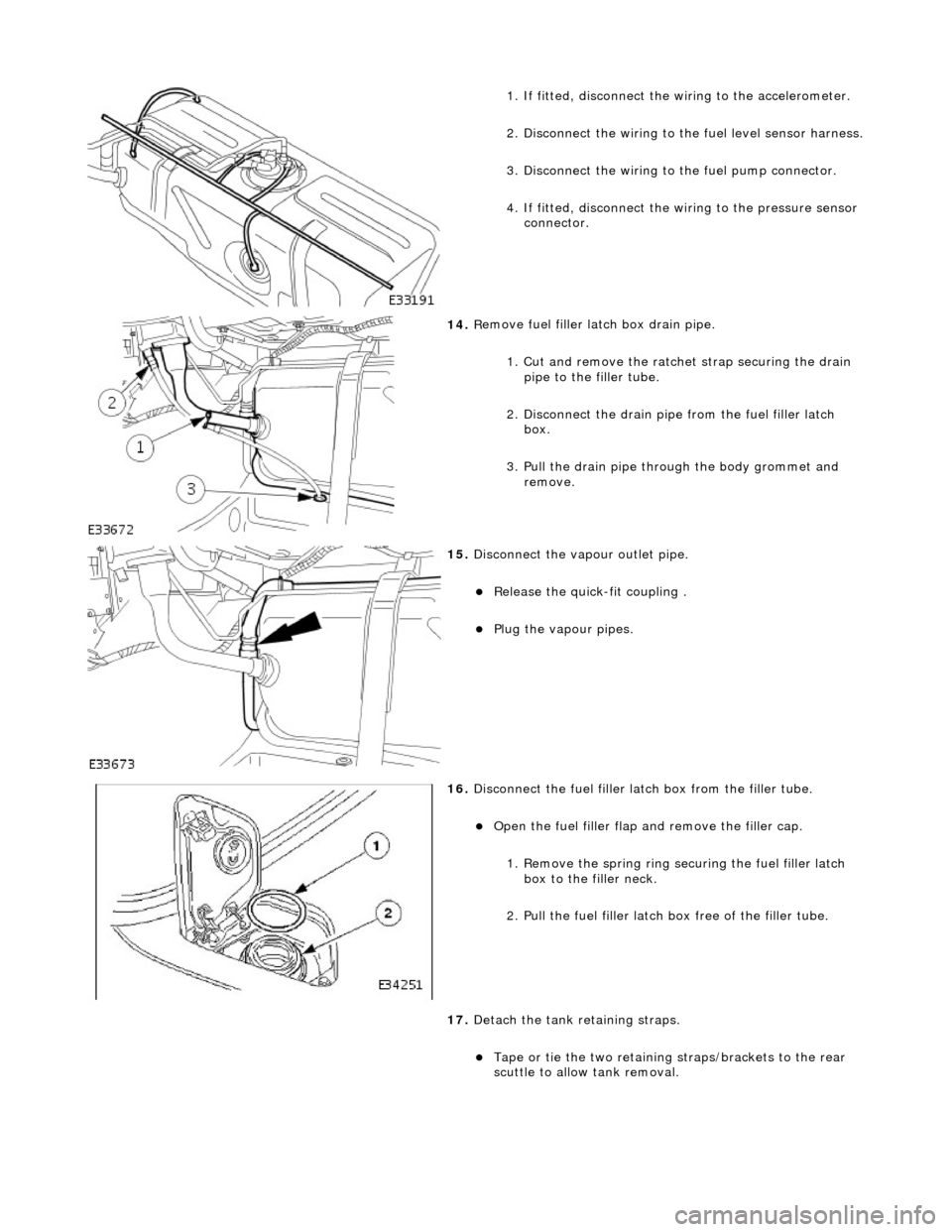
1.
If fitted, disconnect the
wiring to the accelerometer.
2. Disconnect the wiring to the fuel level sensor harness.
3.
Disc
onnect the wiring to
the fuel pump connector.
4. If fitted, disconnect the wi ring to the pressure sensor
connector.
14 . R
emove fuel filler
latch box drain pipe.
1. Cut and remove the ratche t strap securing the drain
pipe to the filler tube.
2. Disconnect the drain pipe from the fuel filler latch box.
3. Pull the drain pipe th rough the body grommet and
remove.
15 . Di
sconnect the vapo
ur outlet pipe.
Relea
se the quick-fit coupling .
Plu
g
the vapour pipes.
16 . D
isconnect the fuel filler la
tch box from the filler tube.
Open t
he fuel filler flap
and remove the filler cap.
1. Remove the spring ring se curing the fuel filler latch
box to the filler neck.
2. Pull the fuel filler latch box free of the filler tube.
17. Detach the tank retaining straps.
Tape or tie the two reta i
ning straps/brackets to the rear
scuttle to allow tank removal.
Page 1737 of 2490
I
nstallation
18
.
On non-ORVR vehicles, disconnect the trunk lid lefthand strut
rear pivot.
Pl
ace a suitable support under
trunk lid or tie to exterior
mirror.
1. Using a screwdriver, release clip at rear end of strut,
withdraw end from trunk lid pivot and lower strut.
19
.
Disconnect the tank ground cable from the vehicle body.
20. Remove the tank from the vehicle.
21. Drain any remaining fuel from the tank.
1. Fit the fuel tank assembly.
2. Re
-connect the tank ground cable to the vehicle.
Tigh
ten to 12 Nm.
3. On non-ORVR fuel tanks, positi on the trunk lid lefthand strut
between the filler tube and the breather pipe.