Page 1738 of 2490
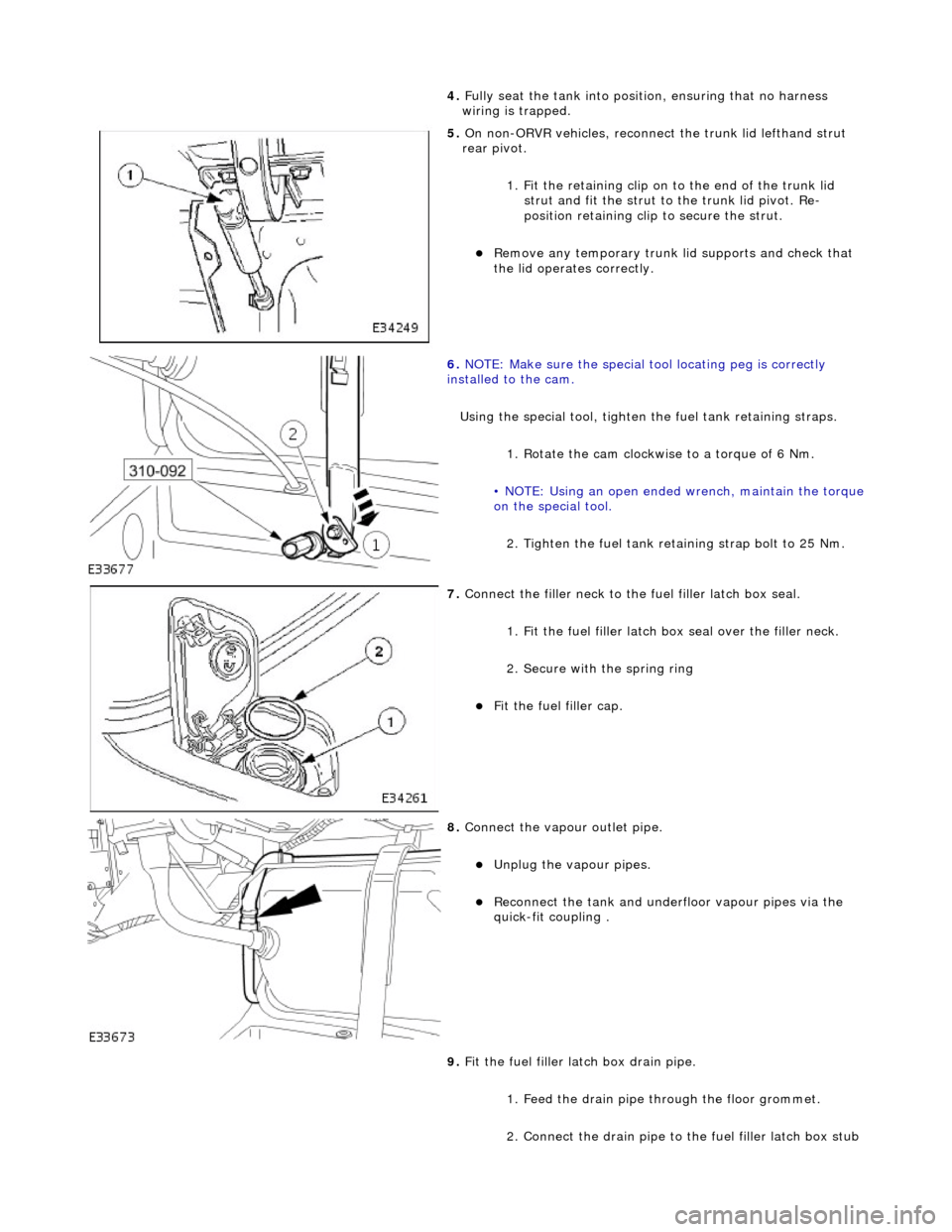
4. Full
y seat the tank into positi
on, ensuring that no harness
wiring is trapped.
5. On non-
ORVR vehicles, reconnec
t the trunk lid lefthand strut
rear pivot.
1. Fit the retaining clip on to the end of the trunk lid strut and fit the strut to the trunk lid pivot. Re-
position retaining clip to secure the strut.
Re
move any temporary trunk lid supports and check that
the lid operates correctly.
6. NOTE
: Make sure the special tool locating peg is correctly
installed to the cam.
Using the special tool, tighten the fuel tank retaining straps.
1. Rotate the cam clockwise to a torque of 6 Nm.
• NOTE: Using an open ended wrench, maintain the torque
on the special tool.
2. Tighten the fuel tank reta ining strap bolt to 25 Nm.
7. Connect the fi
ller neck to the fuel filler latch box seal.
1. Fit the fuel filler latch box seal over the filler neck.
2. Secure with the spring ring
F i
t the fuel filler cap.
8. Connect the vapour outlet pip
e.
Unplug the v
a
pour pipes.
Reconn
ect th
e tank and underfloor vapour pipes via the
quick-fit coupling .
9. Fit the fuel filler latch box drain pipe.
1. Feed the drain pipe th rough the floor grommet.
2. Connect the drain pipe to the fuel filler latch box stub
Page 1739 of 2490
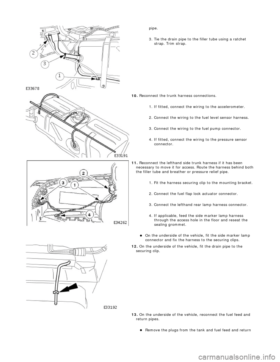
pipe.
3
. Tie the drain pipe to th
e filler tube using a ratchet
strap. Trim strap.
10
.
Reconnect the trunk harness connections.
1. If fitted, connect the wi ring to the accelerometer.
2. Connect the wiring to the fuel level sensor harness.
3. Connect the wiring to th e fuel pump connector.
4. If fitted, connect the wiring to the pressure sensor connector.
11
.
Reconnect the lefthand side trunk harness if it has been
necessary to move it for access. Route the harness behind both
the filler tube and breather or pressure relief pipe.
1. Fit the harness securing cl ip to the mounting bracket.
2. Connect the fuel flap lock actuator connector.
3. Connect the lefthand rear lamp harness connector.
4. If applicable, feed the side marker lamp harness through the access hole in the floor and reseat the
sealing grommet.
On
the underside of the vehicl
e, fit the side marker lamp
connector and fix the harness to the securing clips.
12
.
On the underside of the vehicle, fit the drain pipe to the
securing clip.
13. On the underside of the vehicle, reconnect the fuel feed and
return pipes.
R
emove the plugs from the tank
and fuel feed and return
Page 1740 of 2490
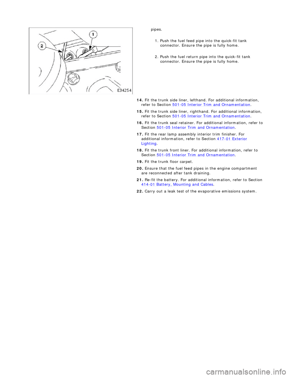
pipes.
1.
Push the fuel feed pipe into the quick-fit tank
connector. Ensu re the pipe is fully home.
2. Push the fuel return pi pe into the quick-fit tank
connector. Ensu re the pipe is fully home.
14. Fit the trunk side liner, lefthand. For additional information,
refer to Section 501
-0 5
Interior Trim and Ornamentation
.
15 . F
it the trunk side liner, righthan
d. For additional information,
refer to Section 501
-0 5
Interior Trim and Ornamentation
.
16 . F
it the trunk seal retainer. For a
dditional information, refer to
Section 501
-05
Interior Trim and Ornamentation
.
17 . F
it the rear lamp assembly
interior trim finisher. For
additional information, refer to Section 417
-01
Exterior
Ligh
ting.
18 . F
it the trunk front liner. For a
dditional information, refer to
Section 501
-05
Interior Trim and Ornamentation
.
19 . F
it the trunk floor carpet.
20. Ensure that the fuel feed pi pes in the engine compartment
are reconnected after tank draining.
21. Re-fit the battery. For additional information, refer to Section
414
-0 1
Battery, Mounting and Cables
.
22 . Carry ou
t a leak test of the evaporative emissions system.
Page 1854 of 2490
Instrument Cluster - Instrument Cluster
Description and Operation
ItemDescription
1Variable Power Steering
2Coolant Level
3Fuel Level
4Oil Pressure
5Lamp Dimmer
6Driver's Switchpack
7Generator (Charge Warning Lamp)
8Catalyst Overheat
9Instrument Cluster
10Climate Control (Signal to Module)
11ICE Head Unit
Page 1855 of 2490
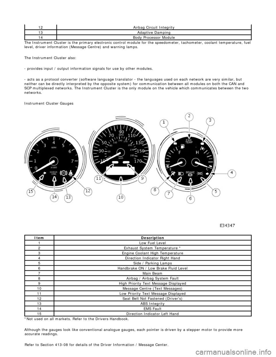
The In
strument Cluster is the primary electronic control module for the speedomete
r, tachometer, coolant temperature, fuel
level, driver information (Message Centre) and warning lamps.
The Instrument Cluster also:
- provides input / output informatio n signals for use by other modules.
- acts as a protocol converter (software language translator - the languages used on each network are very similar, but
neither can be directly interp reted by the opposite system) for communication between all modules on both the CAN and
SCP multiplexed networks. The Instrument Cluster is the only module on the vehicle which communicates between the two
networks.
Instrument Cluster Gauges
*Not used on all markets. Refer to the Drivers Handbook.
Although the gauges look like conventional analogue gauges, each pointer is driven by a stepper motor to provide more
12Ai
rbag Circuit Integrity
13Adaptive Damping
14Body Processor
Module
It
em
De
scription
1Low Fu
el Level
2Exhaus
t System Temperature *
3E
ngine Coolant High Temperature
4Di
rection Indicator Right Hand
5Side
/ Parking Lamps
6Handbrake ON / Low
Bra
ke Fluid Level
7Main
Beam
8Ai
rbag / Airbag System Fault
9Hi
gh Priority Text
Message Displayed
10M
essage Centre (Text Messages)
11Low Pri
ority Text Message Displayed
12Se
at Belt Not Fa
stened (Driver's)
13ABS Integrity
14EMS Fault
15D
irection Indicator Left Hand
accu
rate readings.
Refer to Section 413-08 for details of the Driver Information / Message Center.
Page 1976 of 2490
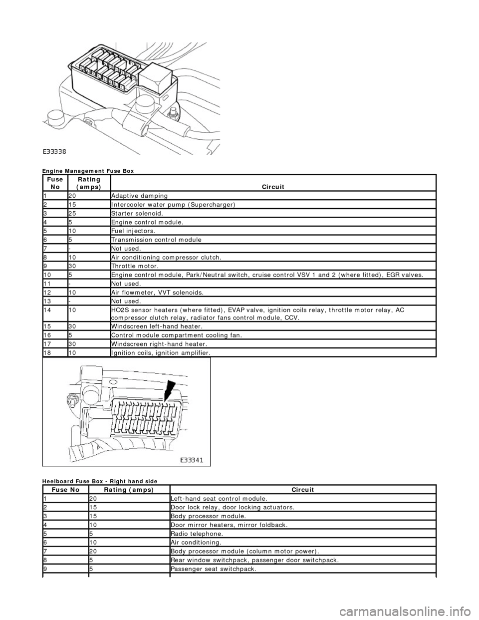
Engine Management Fuse Box
Heelboard Fuse Box - Right hand side
Fuse NoRating
(amps)Circuit
120Adaptive damping
215Intercooler water pump (Supercharger)
325Starter solenoid.
45Engine control module.
510Fuel injectors.
65Transmission control module
7-Not used.
810Air conditioning compressor clutch.
930Throttle motor.
105Engine control module, Park/Neutr al switch, cruise control VSV 1 and 2 (where fitted), EGR valves.
11-Not used.
1210Air flowmeter, VVT solenoids.
13-Not used.
1410HO2S sensor heaters (where fitted ), EVAP valve, ignition coils relay, throttle motor relay, AC
compressor clutch relay, radi ator fans control module, CCV.
1530Windscreen left-hand heater.
165Control module compartment cooling fan.
1730Windscreen right-hand heater.
1810Ignition coils, ignition amplifier.
Fuse NoRating (amps)Circuit
120Left-hand seat control module.
215Door lock relay, door locking actuators.
315Body processor module.
410Door mirror heaters, mirror foldback.
55Radio telephone.
610Air conditioning.
720Body processor module (column motor power).
85Rear window switchpack, passenger door switchpack.
95Passenger seat switchpack.
Page 1978 of 2490
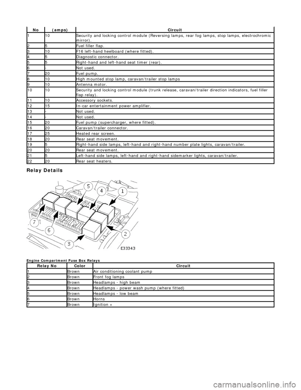
Relay Details
Engine Compartment Fuse Box Relays
No(amps)Circuit
110Security and locking control module (Reversing lamps, rear fog lamps, stop lamps, electrochromic
mirror).
25Fuel filler flap.
310F16 left-hand heelboard (where fitted).
45Diagnostic connector.
55Right-hand and left-han d seat timer (rear).
6-Not used.
720Fuel pump.
810High mounted stop lamp, caravan/trailer stop lamps
910Antenna motor.
1010Security and locking control module (trunk release, caravan/trailer direction indicators, fuel filler
flap relay).
1110Accessory sockets.
1215In-car entertainment power amplifier.
13-Not used.
14-Not used.
1520Fuel pump (supercharger, where fitted).
1620Caravan/trailer connector.
1725Heated rear screen.
1820Rear seat movement.
195Right-hand side lamps, left-h and and right-hand number pl ate lights, caravan/trailer.
2020Rear seat movement.
215Left-hand side lamps, left-hand and right-hand sidemarker lights, caravan/trailer.
2220Rear seat heaters.
Relay NoColorCircuit
1BrownAir conditioning coolant pump
2BrownFront fog lamps
3BrownHeadlamps - high beam
4BrownHeadlamps - power wash pump (where fitted)
5BrownHeadlamps - low beam
6BrownHorns
7BrownIgnition +
Page 1979 of 2490
Engine Management Fuse Box Relay
Engine Compartment - Front Relays
Engine and Transmission Control Module Compartment Relays
Relay NoColorCircuit
1BrownEMS control relay
Relay NoColorCircuit
1BlackWindshield wiper fast/slow
2BlackWindshield wiper on/off
Relay NoColorCircuit
1BlueSC coolant water pump
2BrownFuel injection main
3BrownIgnition coils
4BrownThrottle motor
5BrownStarter solenoid
6BrownAir conditioning compressor clutch