Page 1505 of 2490
Shift Selection and Gear Position
Symptom Chart
Pinpoint test A: P0705
Loose selector disc seal
*
SymptomPossible SourcesAction
DTC P0705 Transmission range sensor circuit
malfunctionSelector cable maladjusted
Linear switch maladjusted
Linear position switch fault
Harness fault
Connector pins(s) bent, loose or
corroded
*
*
*
*
*GO to Pinpoint Test
A
*
PINPOINT TEST A : P0705
TEST CONDITIONSDETAILS/RESULTS/ACTIONS
A1: RETRIEVE DTCS
• NOTE: Battery and or ECM disconnection prior to scanning wi
ll erase all data, ensure that the correct DTC is present.
Connect the scan tool 1
Have the DTC(s) and freeze frame data been recorded?
Yes GO to A2
A2: STATUS / RELATIONSHIP CHECK
Move the selector lever sl owly from P to 2 and back,
noting the illumination / positi on relationship as follows: 1
Does state illumination match the lever position in each
direction of travel?
Yes
GO to A4
No GO to A3
No With lever at D (when moving from 2 to P ) is 3 or 4
illuminated?
Yes GO to A3
Page 1530 of 2490
The upstream heated oxygen sensor is located at the catalytic converter inlet and detects the concentration of oxygen in the
raw exhaust gases; an internal heater reduces the warm up time of the sensor output.
An oxygen sensor (without heater) is located at the converter outlet.
The ECM receives input signals from the se nsors and varies the fuel injector duration (mixture) to provide optimum gas
emissions.
Circuit Diagram, O2 Sensors / ECM
Page 1531 of 2490
Inspection and Verification
Vehicle Harness Check
1.1. Check for open and short circuit in harness conn ector faults between the O2 sensor and ECM.
2. 2. Check for approximately 12V between heater harness.
ItemDescription
1ECM
2Downstream oxygen sensor (A)
3Upstream heated oxygen sensor (A)
4Downstream oxygen sensor (B)
5Upstream heated oxygen sensor (B)
6Engine management fuse box
Page 1533 of 2490

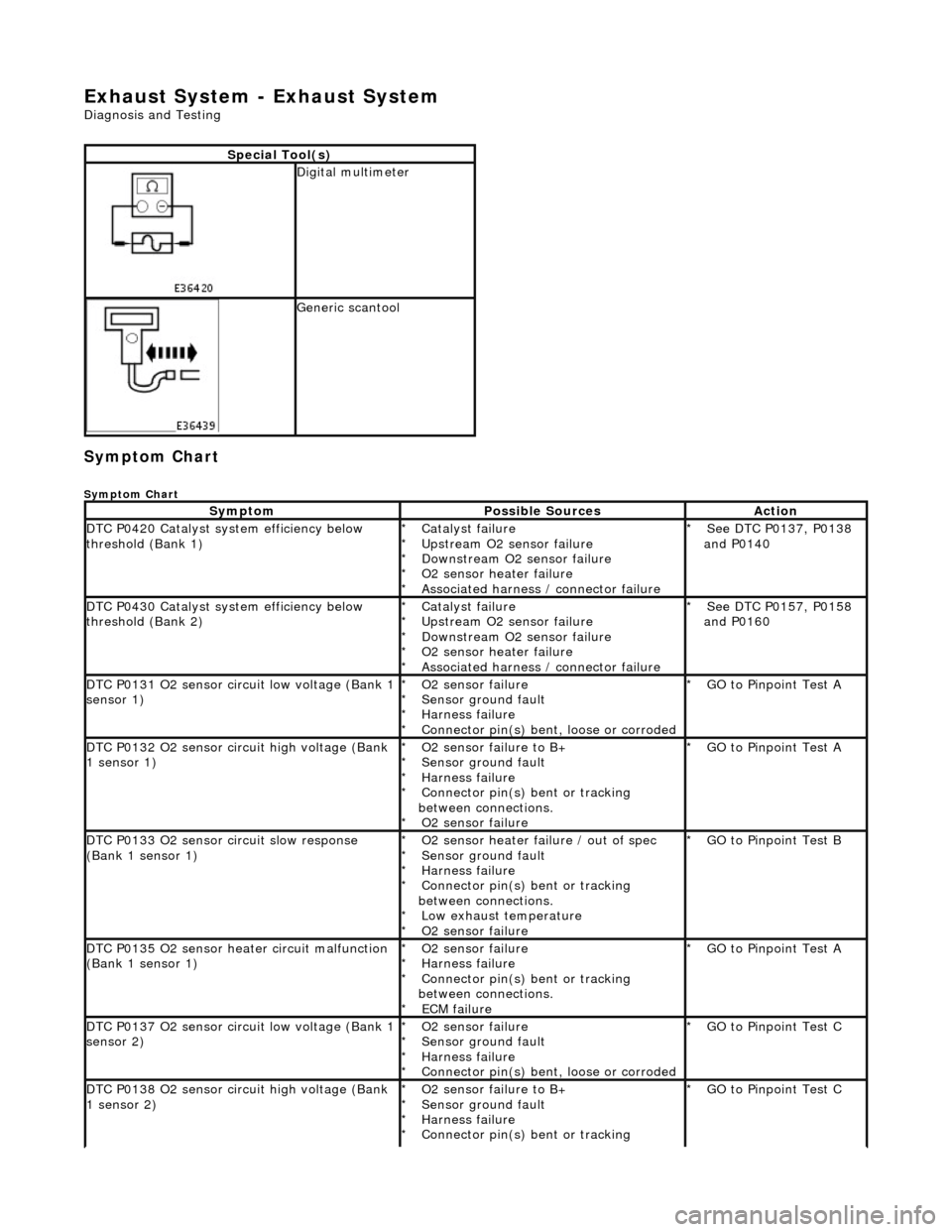
Exhaust System - Exhaust System
Diagnosis and Testing
Symptom Chart
Symptom Chart
Special Tool(s)
Digital multimeter
Generic scantool
SymptomPossible SourcesAction
DTC P0420 Catalyst system efficiency below
threshold (Bank 1)Catalyst failure
Upstream O2 sensor failure
Downstream O2 sensor failure
O2 sensor heater failure
Associated harness / connector failure
*
*
*
*
*See DTC P0137, P0138
and P0140
*
DTC P0430 Catalyst system efficiency below
threshold (Bank 2)Catalyst failure
Upstream O2 sensor failure
Downstream O2 sensor failure
O2 sensor heater failure
Associated harness / connector failure
*
*
*
*
*See DTC P0157, P0158
and P0160
*
DTC P0131 O2 sensor circuit low voltage (Bank 1
sensor 1)O2 sensor failure
Sensor ground fault
Harness failure
Connector pin(s) bent, loose or corroded
*
*
*
*GO to Pinpoint Test A
*
DTC P0132 O2 sensor circuit high voltage (Bank
1 sensor 1)O2 sensor failure to B+
Sensor ground fault
Harness failure
Connector pin(s) bent or tracking
between connections. O2 sensor failure
*
*
*
*
*GO to Pinpoint Test A
*
DTC P0133 O2 sensor circuit slow response
(Bank 1 sensor 1)O2 sensor heater failure / out of spec
Sensor ground fault
Harness failure
Connector pin(s) bent or tracking
between connections. Low exhaust temperature
O2 sensor failure
*
*
*
*
*
*GO to Pinpoint Test B
*
DTC P0135 O2 sensor heater circuit malfunction
(Bank 1 sensor 1)O2 sensor failure
Harness failure
Connector pin(s) bent or tracking
between connections. ECM failure
*
*
*
*GO to Pinpoint Test A
*
DTC P0137 O2 sensor circuit low voltage (Bank 1
sensor 2)O2 sensor failure
Sensor ground fault
Harness failure
Connector pin(s) bent, loose or corroded
*
*
*
*GO to Pinpoint Test C
*
DTC P0138 O2 sensor circuit high voltage (Bank
1 sensor 2)O2 sensor failure to B+
Sensor ground fault
Harness failure
Connector pin(s) bent or tracking
*
*
*
*GO to Pinpoint Test C
*
Page 1534 of 2490

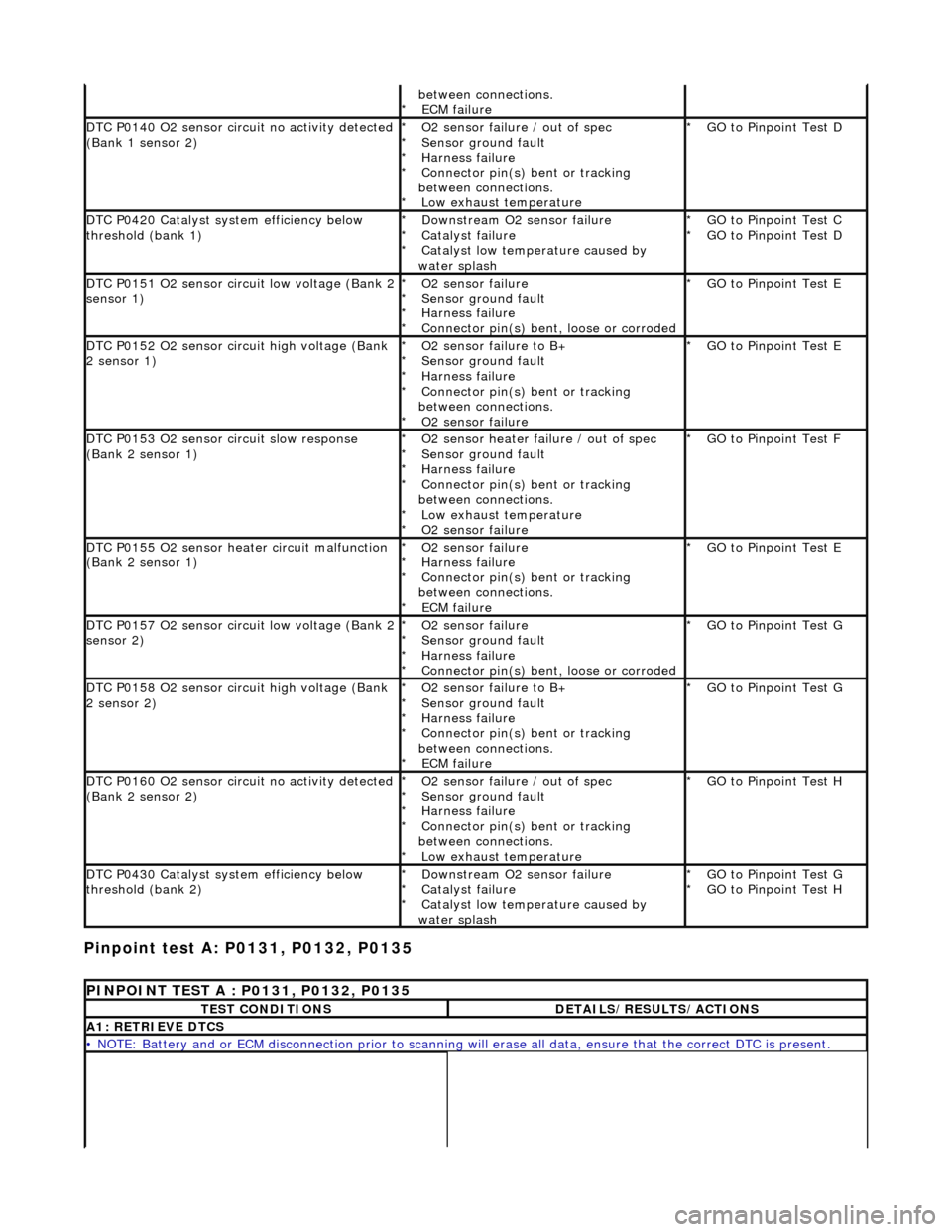
Pinpoint test A: P0131, P0132, P0135
between connections. ECM failure
*
DTC P0140 O2 sensor circuit no activity detected
(Bank 1 sensor 2)O2 sensor failure / out of spec
Sensor ground fault
Harness failure
Connector pin(s) bent or tracking
between connections. Low exhaust temperature
*
*
*
*
*GO to Pinpoint Test D
*
DTC P0420 Catalyst system efficiency below
threshold (bank 1)Downstream O2 sensor failure
Catalyst failure
Catalyst low temperature caused by
water splash
*
*
*GO to Pinpoint Test C
GO to Pinpoint Test D
*
*
DTC P0151 O2 sensor circuit low voltage (Bank 2
sensor 1)O2 sensor failure
Sensor ground fault
Harness failure
Connector pin(s) bent, loose or corroded
*
*
*
*GO to Pinpoint Test E
*
DTC P0152 O2 sensor circuit high voltage (Bank
2 sensor 1)O2 sensor failure to B+
Sensor ground fault
Harness failure
Connector pin(s) bent or tracking
between connections. O2 sensor failure
*
*
*
*
*GO to Pinpoint Test E
*
DTC P0153 O2 sensor circuit slow response
(Bank 2 sensor 1)O2 sensor heater failure / out of spec
Sensor ground fault
Harness failure
Connector pin(s) bent or tracking
between connections. Low exhaust temperature
O2 sensor failure
*
*
*
*
*
*GO to Pinpoint Test F
*
DTC P0155 O2 sensor heater circuit malfunction
(Bank 2 sensor 1)O2 sensor failure
Harness failure
Connector pin(s) bent or tracking
between connections. ECM failure
*
*
*
*GO to Pinpoint Test E
*
DTC P0157 O2 sensor circuit low voltage (Bank 2
sensor 2)O2 sensor failure
Sensor ground fault
Harness failure
Connector pin(s) bent, loose or corroded
*
*
*
*GO to Pinpoint Test G
*
DTC P0158 O2 sensor circuit high voltage (Bank
2 sensor 2)O2 sensor failure to B+
Sensor ground fault
Harness failure
Connector pin(s) bent or tracking
between connections. ECM failure
*
*
*
*
*GO to Pinpoint Test G
*
DTC P0160 O2 sensor circuit no activity detected
(Bank 2 sensor 2)O2 sensor failure / out of spec
Sensor ground fault
Harness failure
Connector pin(s) bent or tracking
between connections. Low exhaust temperature
*
*
*
*
*GO to Pinpoint Test H
*
DTC P0430 Catalyst system efficiency below
threshold (bank 2)Downstream O2 sensor failure
Catalyst failure
Catalyst low temperature caused by
water splash
*
*
*GO to Pinpoint Test G
GO to Pinpoint Test H
*
*
PINPOINT TEST A : P0131, P0132, P0135
TEST CONDITIONSDETAILS/RESULTS/ACTIONS
A1: RETRIEVE DTCS
• NOTE: Battery and or ECM disconnection prior to scanning wi
ll erase all data, ensure that the correct DTC is present.
Page 1542 of 2490
Ignition switch to position 0 1
Disconnect EM010 and EM012
Inside ECM housing
2
Ignition switch to position II 3
Measure the voltage between EM010/023 and EM012/015 4
Is the voltage 0 (zero) V?
Yes GO to A15
No Inspect harness / connectors EM010, EM012, and EM021 for
corrosion, damaged / pushed back pins. Repair as required
and reconnect plug(s).
GO to A18
A15: CHECK FOR SHORT TO B+
Measure the voltage between EM010/023 and EM012/022 1
Page 1544 of 2490
Ignition switch to position 0 1
Remove EMS fuse F14 2
Disconnect EM010 and EM015
Inside ECM housing
3
Using a link lead, bridge EM010/016 and EM010/022 4
Ignition switch to position II 5
Measure the voltage between EM010/023 and EM015/002 6
Is the voltage 0 (zero) V?
Yes Replace EMS fuse F14 but retain link lead
GO to A17
No Inspect harness / connectors EM010, EM015, and EM021 for
corrosion, damaged / pushed back pins. Repair as necessary
and reconnect plug(s).
GO to A18
A17: CHECK B+ AT O2 SENSOR HEATER CIRCUIT
Page 1545 of 2490
Pinpoint test B: P0133
Measure the voltage between EM010/023 and EM015/002 1
Is the voltage B+?
Yes Remove link lead and reconnect all connectors
GO to A18
No Check EMS fuse F14 and that EMS control relay (relay 1) is
energized and with all connections made.
GO to A18
A18: END
Perform appropriate service drive cycle and check for the
presence of DTC. 1
Has the fault code cleared?
Yes STOP
No Contact Jaguar Service
PINPOINT TEST B : P0133
TEST CONDITIONSDETAILS/RESULTS/ACTIONS
B1: RETRIEVE DTCS
• NOTE: Battery and or ECM disconnection prior to scanning wi ll erase all data, ensure that the correct DTC is present.