1998 JAGUAR X308 ECM
[x] Cancel search: ECMPage 1750 of 2490
Is t
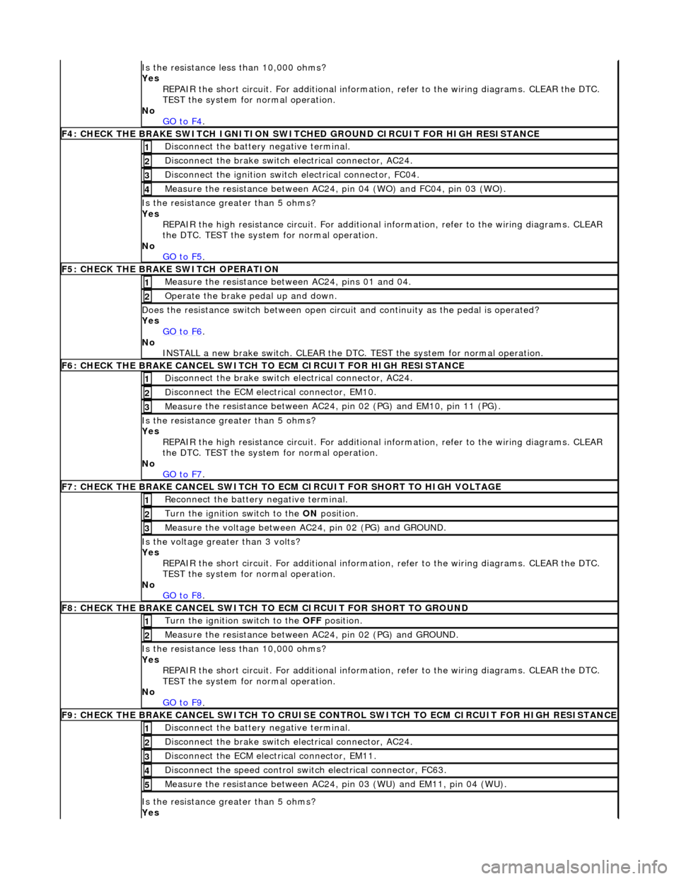
he resistance less than 10,000 ohms?
Yes REPAIR the short circuit. For addi tional information, refer to the wiring diagrams. CLEAR the DTC.
TEST the system for normal operation.
No GO to F4
.
F4: CHECK THE BRAKE SWITCH IGNITION SWIT
C
HED GROUND CIRCUIT FOR HIGH RESISTANCE
Di
sc
onnect the battery negative terminal.
1
Di
sc
onnect the brake switch electrical connector, AC24.
2
Di
sc
onnect the ignition switch electrical connector, FC04.
3
Measure t
he resistance between AC24,
pin 04 (WO) and FC04, pin 03 (WO).
4
Is the res
istance greater than 5 ohms?
Yes REPAIR the high resistance circui t. For additional information, refer to the wiring diagrams. CLEAR
the DTC. TEST the system for normal operation.
No GO to F5
.
F5: CHECK THE BRAKE SWITCH O
PERATION
Me
asure
the resistance between AC24, pins 01 and 04.
1
O
p
erate the brake pedal up and down.
2
Doe
s
the resistance switch between open circuit and continuity as the pedal is operated?
Yes GO to F6
.
No
INST
ALL a new brake switch. CLEAR the DTC.
TEST the system for normal operation.
F6: CHECK THE BRAKE CANCEL
SWITCH
TO ECM CIRCUIT FOR HIGH RESISTANCE
Disc
onnect the brake switch electrical connector, AC24.
1
D
i
sconnect the ECM electrical connector, EM10.
2
Me
asure
the resistance between AC24, pin 02 (PG) and EM10, pin 11 (PG).
3
Is th
e res
istance greater than 5 ohms?
Yes REPAIR the high resistance circui t. For additional information, refer to the wiring diagrams. CLEAR
the DTC. TEST the system for normal operation.
No GO to F7
.
F7: CHECK THE BRAKE CANCEL
SWITCH TO
ECM CIRCUIT FOR SHORT TO HIGH VOLTAGE
Re
connect the battery negative terminal.
1
Turn the ignition swi
t
ch to the ON
position.
2
Me
asure the voltage between AC24, pin 02 (PG) and GROUND.
3
Is th
e volt
age greater than 3 volts?
Yes REPAIR the short circuit. For addi tional information, refer to the wiring diagrams. CLEAR the DTC.
TEST the system for normal operation.
No GO to F8
.
F8: CHECK THE BRAKE CANCEL
SWITCH
TO ECM CIRCUIT FO R SHORT TO GROUND
Turn the ignition swit
ch to the OFF
position.
1
Measure t
he resistance between AC24, pin 02 (PG) and GROUND.
2
Is
t
he resistance less than 10,000 ohms?
Yes REPAIR the short circuit. For addi tional information, refer to the wiring diagrams. CLEAR the DTC.
TEST the system for normal operation.
No GO to F9
.
F9: CHECK THE BRAKE CANCEL
SWITCH
TO CRUISE CONTROL SWITCH TO ECM CIRCUIT FOR HIGH RESISTANCE
Disc
onnect the battery negative terminal.
1
Di
sc
onnect the brake switch electrical connector, AC24.
2
D
i
sconnect the ECM electrical connector, EM11.
3
Di
sc
onnect the speed control switch electrical connector, FC63.
4
Me
asure
the resistance between AC24, pin 03 (WU) and EM11, pin 04 (WU).
5
Is th
e res
istance greater than 5 ohms?
Yes
Page 1751 of 2490
R
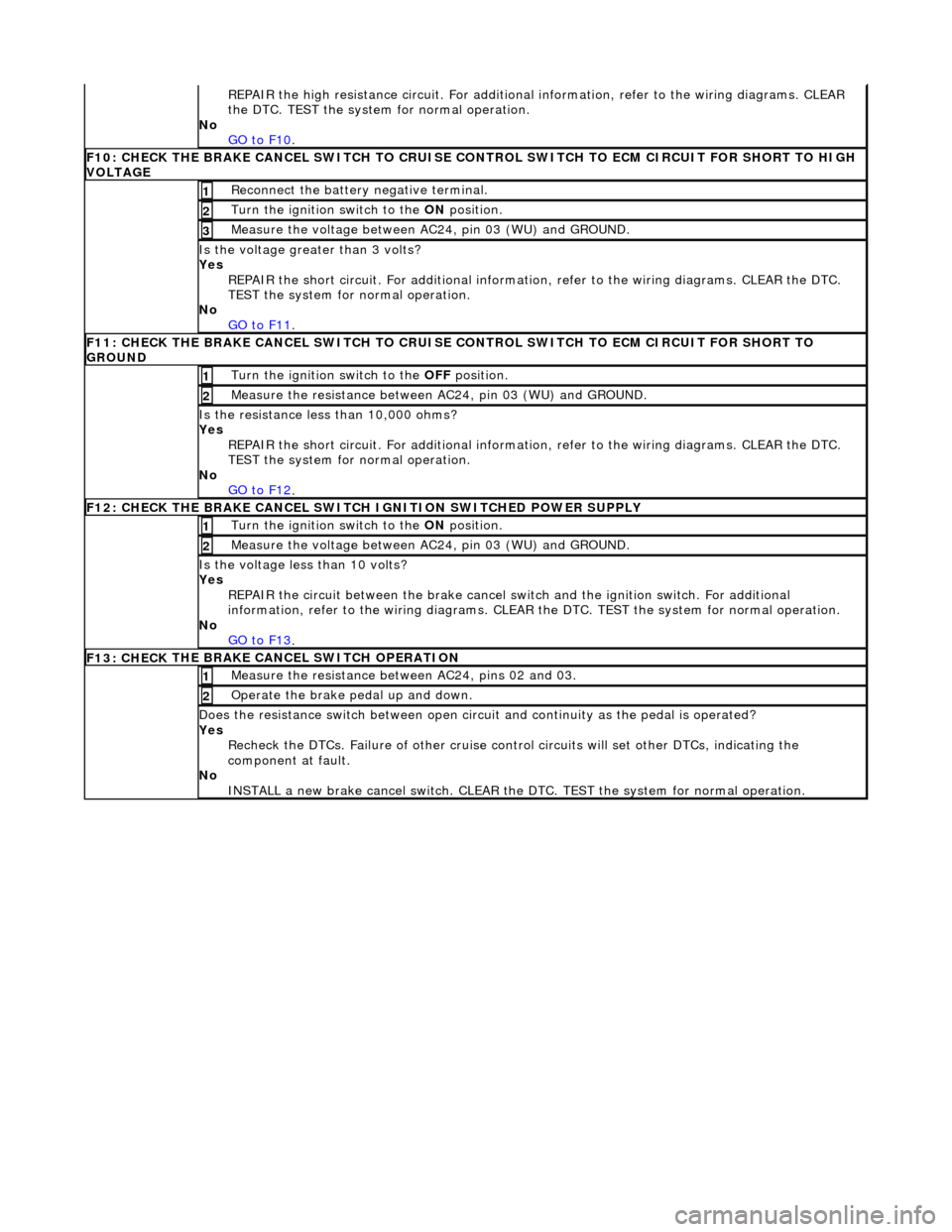
EPAIR the high resistance circui
t. For additional information, refer to the wiring diagrams. CLEAR
the DTC. TEST the system for normal operation.
No GO to F10
.
F10: CHECK
THE BRAKE CANCEL SWITCH TO CRUISE CO
NTROL SWITCH TO ECM CIRCUIT FOR SHORT TO HIGH
VOLTAGE
R
econnect the battery negative terminal.
1
Turn the ignition swi
tch to the ON
position.
2
M
easure the voltage between AC24, pin 03 (WU) and GROUND.
3
Is th
e voltage greater than 3 volts?
Yes REPAIR the short circuit. For addi tional information, refer to the wiring diagrams. CLEAR the DTC.
TEST the system for normal operation.
No GO to F11
.
F11: CHECK
THE BRAKE CANCEL SWITCH TO CRUISE
CONTROL SWITCH TO ECM CIRCUIT FOR SHORT TO
GROUND
Turn the ignition swi
tch to the
OFF position.
1
Meas
ure the resistance between AC24, pin 03 (WU) and GROUND.
2
Is
the resistance less than 10,000 ohms?
Yes REPAIR the short circuit. For addi tional information, refer to the wiring diagrams. CLEAR the DTC.
TEST the system for normal operation.
No GO to F12
.
F12: CHECK
THE BRAKE CANCEL SWITCH
IGNITION SWITCHED POWER SUPPLY
Turn the ignition swi
tch to the ON
position.
1
M
easure the voltage between AC24, pin 03 (WU) and GROUND.
2
Is th
e voltage less than 10 volts?
Yes REPAIR the circuit between the brake cancel sw itch and the ignition switch. For additional
information, refer to the wiring diagrams. CLEAR the DTC. TEST the system for normal operation.
No GO to F13
.
F13: CHECK
THE BRAKE CA
NCEL SWITCH OPERATION
Me
asure the resistance between AC24, pins 02 and 03.
1
O
perate the brake pedal up and down.
2
Doe
s the resistance switch between open circuit and continuity as the pedal is operated?
Yes Recheck the DTCs. Failure of other cruise contro l circuits will set other DTCs, indicating the
component at fault.
No INSTALL a new brake cancel switch. CLEAR the DT C. TEST the system for normal operation.
Page 1758 of 2490
Climate Control System - General Informatio
n - Climate Control System
D
iagn
osis and Testing
I
n
troduction
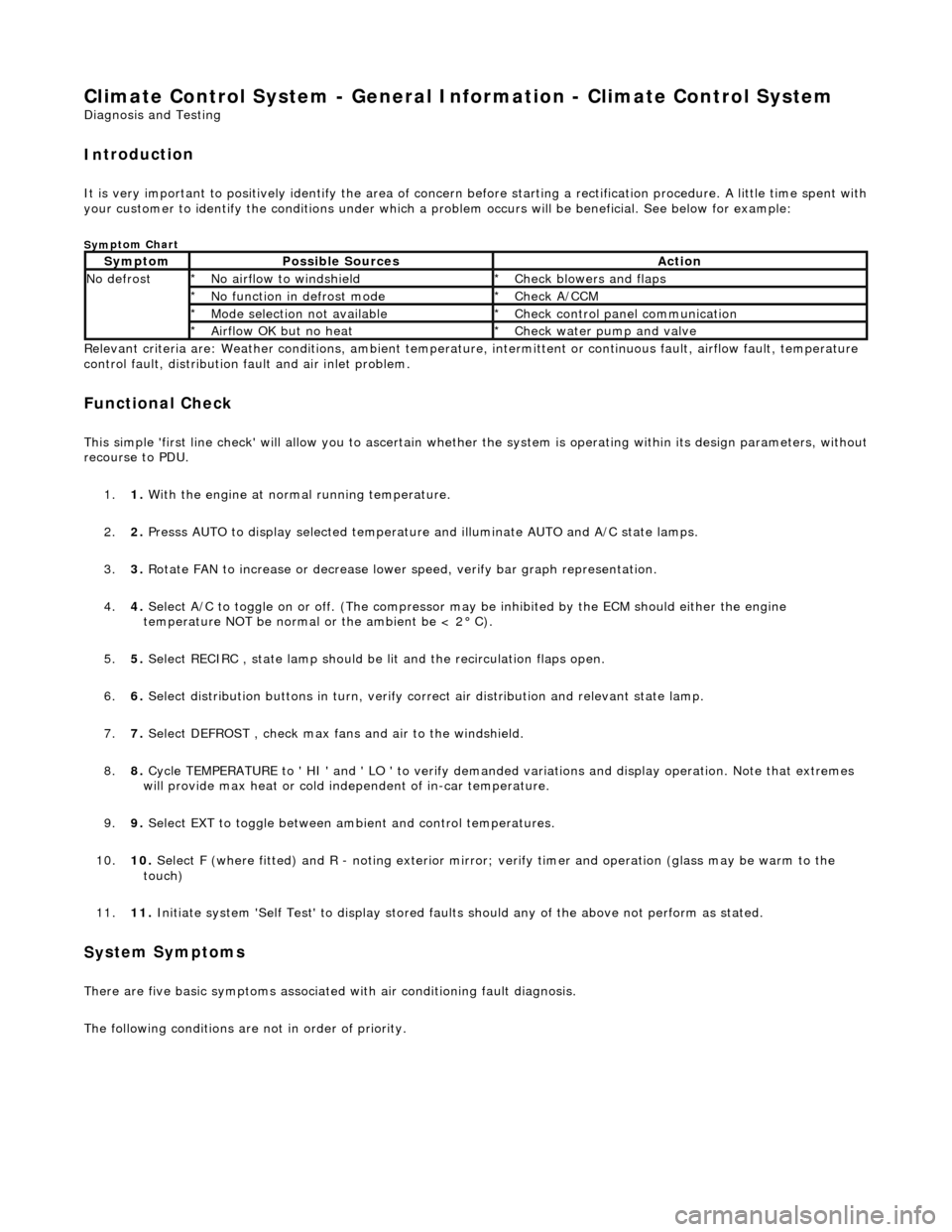
It is very i
m
portant to positive
ly identify the area of concern before starting a rectification procedure. A little time spent with
your customer to identify the conditions under which a pr oblem occurs will be beneficial. See below for example:
Sym
ptom Chart
Re
lev
ant criteria are: Weather conditions,
ambient temperature, intermittent or cont inuous fault, airflow fault, temperature
control fault, distribution fault and air inlet problem.
Functio n
al Check
This
s
imple 'first line check' will allo
w you to ascertain whether the system is operating within its design parameters, withou t
recourse to PDU.
1. 1. With the engine at normal running temperature.
2. 2. Presss AUTO to display selected temperature and illuminate AUTO and A/C state lamps.
3. 3. Rotate FAN to increase or decrease lowe r speed, verify bar graph representation.
4. 4. Select A/C to toggle on or off. (T he compressor may be inhibited by the ECM should either the engine
temperature NOT be normal or the ambient be < 2° C).
5. 5. Select RECIRC , state lamp should be lit and the recirculation flaps open.
6. 6. Select distribution butt ons in turn, verify correct air distribution and relevant state lamp.
7. 7. Select DEFROST , check max fans and air to the windshield.
8. 8. Cycle TEMPERATURE to ' HI ' and ' LO ' to verify demanded variations and display operation. Note that extremes
will provide max heat or cold independent of in-car temperature.
9. 9. Select EXT to toggle between am bient and control temperatures.
10. 10. Select F (where fitted) and R - noting exterior mirror; verify timer and operation (glass may be warm to the
touch)
11. 11. Initiate system 'Self Test' to display stored faul ts should any of the above not perform as stated.
Sy
stem Symptoms
There
are five
basic symptoms associated
with air conditioning fault diagnosis.
The following conditions are not in order of priority.
Sy m
ptom
Possib
l
e Sources
Acti
o
n
N
o defrostN o
airflow to windshield
*
Check blower s and flaps
*
N o functi
on in defrost mode
*
Check A/CCM
*
Mo de s
election not available
*
Chec k
control panel communication
*
Ai rfl
ow OK but no heat
*
Check water pu
mp and valve
*
Page 1800 of 2490
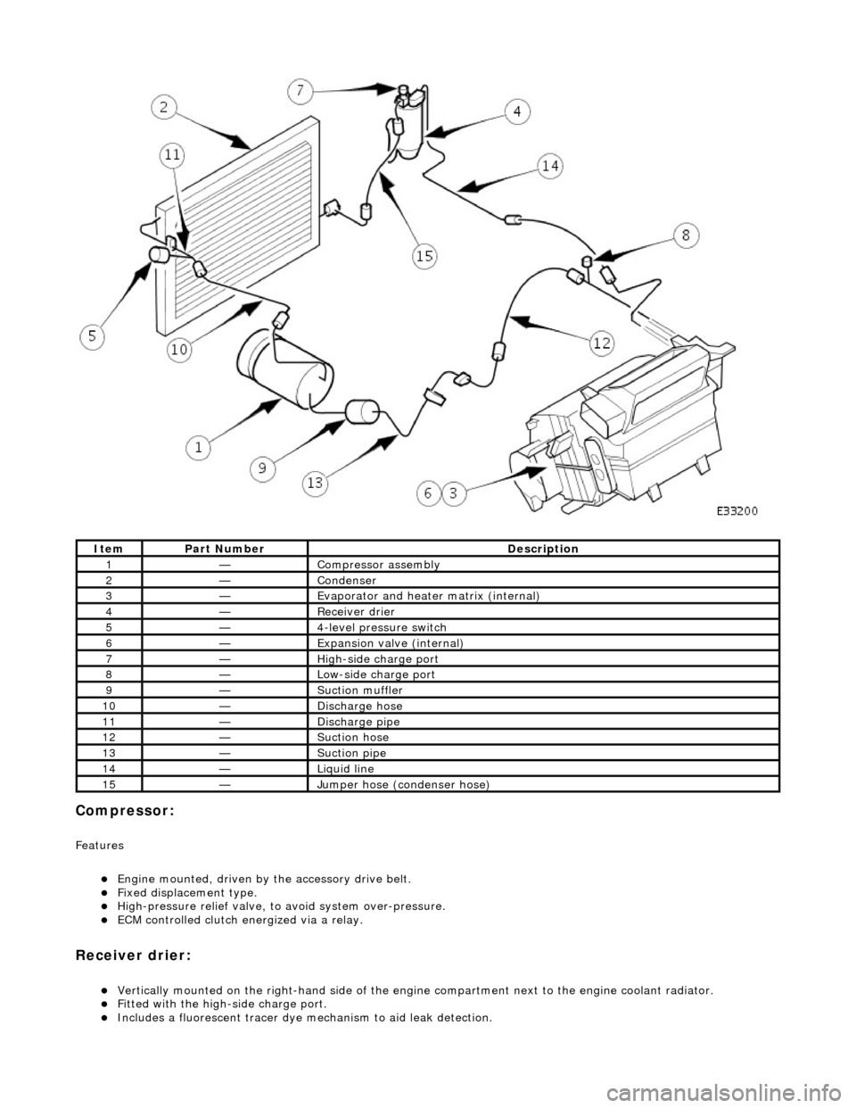
Compressor:
Features
Engine mounted, driven by the accessory drive belt. Fixed displacement type. High-pressure relief valve, to avoid system over-pressure. ECM controlled clutch energized via a relay.
Receiver drier:
Vertically mounted on the ri ght-hand side of the engine compartment next to the engine coolant radiator. Fitted with the high-side charge port. Includes a fluorescent tracer dye me chanism to aid leak detection.
ItemPart NumberDescription
1—Compressor assembly
2—Condenser
3—Evaporator and heater matrix (internal)
4—Receiver drier
5—4-level pressure switch
6—Expansion valve (internal)
7—High-side charge port
8—Low-side charge port
9—Suction muffler
10—Discharge hose
11—Discharge pipe
12—Suction hose
13—Suction pipe
14—Liquid line
15—Jumper hose (condenser hose)
Page 1801 of 2490
Condenser:
Multi-pass fin-over-tube type, mounted in front of the engine cooling pack and directly to the radiator.
Pressure (Bitron) switch:
Located in the discharge pipe. Provides a signal, via the A/CCM, to th e ECM, to disengage the compressor clut ch should the refrigerant pressure be
< 2 bar or > 30 bar.
Provides a hard-wired signal to the ECM, to switch the cool ing fans to HIGH speed at 22 bar rising pressure and to
LOW speed at 17,5 bar falling pressure.
Provides a hard-wired signal to the ECM, to switch the radiator cooling fans to LOW speed at 12 bar rising pressure
and to switch the fans OFF at 8 bar falling pressure.
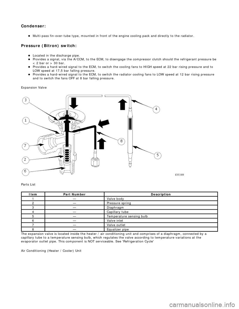
Expansion Valve
Parts List
The expansion valve is located inside the heater / air conditioning unit and comprises of a diaphragm, connected by a
capillary tube to a temperat ure sensing bulb, which regulates the valve according to temperature variations at the
evaporator outlet pipe. This component is NOT serviceable. See 'Refrigeration Cycle'
Air Conditioning (Heater / Cooler) Unit
ItemPart NumberDescription
1—Valve body
2—Pressure spring
3—Diaphragm
4—Capillary tube
5—Temperature sensing bulb
6—Valve inlet
7—Valve outlet
8—Equalizer pipe
Page 1828 of 2490
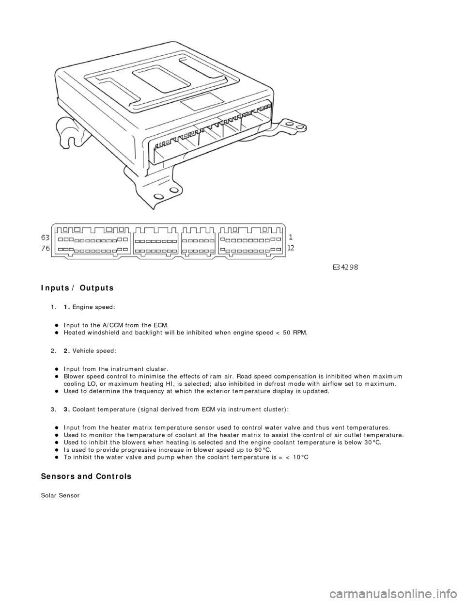
Inputs / Outputs
1.1. Engine speed:
Input to the A/CCM from the ECM. Heated windshield and backli ght will be inhibited when engine speed < 50 RPM.
2. 2. Vehicle speed:
Input from the instru ment cluster. Blower speed control to minimise the effects of ram ai r. Road speed compensation is inhibited when maximum
cooling LO, or maximum heating HI, is selected; also inhi bited in defrost mode with airflow set to maximum.
Used to determine the frequency at which the exterior temperature display is updated.
3. 3. Coolant temperature (signal derived from ECM via instrument cluster):
Input from the heater matrix temperature sensor used to control water valve and thus vent temperatures. Used to monitor the temperature of coolant at the heater matrix to assist the control of air outlet temperature. Used to inhibit the blowers when heating is selected and the engine coolant temperature is below 30°C. Is used to provide progressive increase in blower speed up to 60°C. To inhibit the water valve and pump when the coolant temperature is = < 10°C
Sensors and Controls
Solar Sensor
Page 1834 of 2490
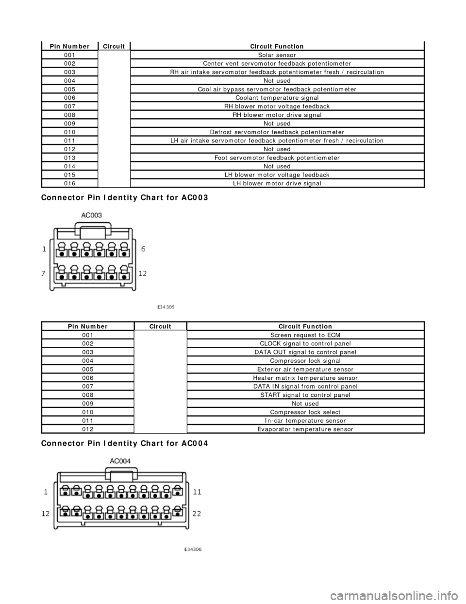
Connector Pin Identity Chart for AC003
Connector Pin Identity Chart for AC004
Pin NumberCircuitCircuit Function
001Solar sensor
002Center vent servomotor feedback potentiometer
003RH air intake servomotor feedback potentiometer fresh / recirculation
004Not used
005Cool air bypass servomotor feedback potentiometer
006Coolant temperature signal
007RH blower motor voltage feedback
008RH blower motor drive signal
009Not used
010Defrost servomotor feedback potentiometer
011LH air intake servomotor feedback potentiometer fresh / recirculation
012Not used
013Foot servomotor feedback potentiometer
014Not used
015LH blower motor voltage feedback
016LH blower motor drive signal
Pin NumberCircuitCircuit Function
001Screen request to ECM
002CLOCK signal to control panel
003DATA OUT signal to control panel
004Compressor lock signal
005Exterior air temperature sensor
006Heater matrix temperature sensor
007DATA IN signal from control panel
008START signal to control panel
009Not used
010Compressor lock select
011In-car temperature sensor
012Evaporator temperature sensor
Page 1835 of 2490
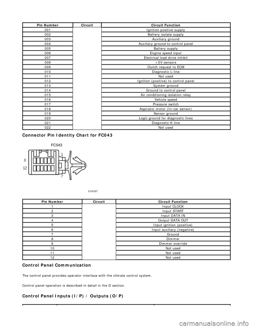
Connector Pin Identity Chart for FC043
Control Panel Communication
The control panel provides operator interface with the climate control system.
Control panel operation is described in detail in the D section.
Control Panel Inputs (I/P) / Outputs (O/P)
Pin NumberCircuitCircuit Function
001Ignition positive supply
002Battery isolate supply
003Auxiliary ground
004Auxiliary ground to control panel
005Battery supply
006Engine speed input
007Electrical load drive inhibit
008+5V sensors
009Clutch request to ECM
010Diagnostic L-line
011Not used
012Ignition (positive) to control panel
013System ground
014Ground to control panel
015Air conditioning isolation relay
016Vehicle speed
017Pressure switch
018Aspirator motor (In-car sensor)
019Sensor ground
020Logic ground for diagnostic lines
021Diagnostic K-line
022Not used
Pin NumberCircuitCircuit Function
1Input CLOCK
2Input START
3Input DATA IN
4Output DATA OUT
5Input ignition (positive)
6Input auxiliary (negative)
7Ground
8Dimmer
9Dimmer override
10Not used
11Not used
12Not used