Page 1116 of 2490

Intake Air Distribution and Filtering - Air Cleaner
Remo
val and Installation
Remov
a
l
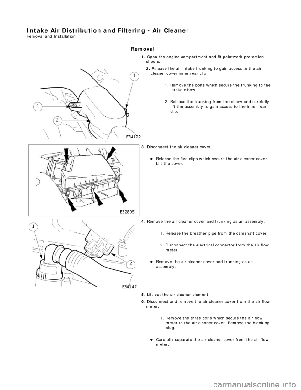
1.
Op
en the engine compartment and fit paintwork protection
sheets.
2. Relea
se the air intake trunking
to gain access to the air
cleaner cover inner rear clip
1. Remove the bolts which secure the trunking to the intake elbow.
2. Release the trunking from the elbow and carefully lift the assembly to gain access to the inner rear
clip.
3. Disc
onnect the air cleaner cover.
R
e
lease the five clips which se
cure the air cleaner cover.
Lift the cover.
4. Re
move the air cleaner cover an
d trunking as an assembly.
1. Release the breather pipe from the camshaft cover.
2. Disconnect the electrical connector from the air flow meter.
Re
move the air cleaner cover and trunking as an
assembly.
5. Lift out the air cleaner element.
6. Disconnect and remove the air cleaner cover from the air flow
meter.
1. Remove the three bolts which secure the air flow
meter to the air cleaner co ver. Remove the blanking
plug.
Carefull y separate the ai
r clea
ner cover from the air flow
meter.
Page 1138 of 2490
7. Re
move engine covers
8. Disc onne
ct electrical connector from each fuel injector.
9. Disc
onnect fuel feed hose.
1. Use special tool 310-044 (JD 182).
10. Disconnect fuel return hose.
1. Use special tool 310-054 (JD 203).
Page 1140 of 2490
In
stallation
15.
Cle
an manifold and mating faces on cylinder heads.
1. Where necessary, install blanking plate to intake elbow.
Inst al
l new gasket.
Inst
al
l bolts (18-24Nm).
2. Inst al
l intake elbow to intake manifold.
1. Install new seal.
2. Install seven bolts.
3. Install new seals to the eight intake manifold ports. Ensure the
seals are fully seated.
4. Inst al
l intake manifold.
1. Install ten bolts.
5. Connect fuel feed hose to fuel rail feed pipe. Ensure hose is
fully installed.
6. Connect fuel return hose to fuel rail return pipe. Ensure hose is
fully installed.
7. Con n
ect electrical connectors to fuel injectors.
8. Install left-hand support brac ket to intake elbow and re-
connect pipework.
1. Install bolt.
Page 1148 of 2490

Evaporative E
missions - Evaporative Emissions
Description an
d Operation
To reduce the emission of fuel vapour, th e fuel tank is vented to atmosphere through activated charcoal adsorption canister
(s) which collects the fuel droplets. The ch arcoal is periodically purged of fuel when the EVAP Canister Purge Valve opens
the vapour line between the canister(s) and the air intake induct ion elbow. This action allows manifold depression to draw
air through the canister atmospheric vent, taking up the deposited fuel from the charcoal adsorber and burning the resulting
fuel vapour in the engine.
The EVAP Canister Purge Valve is controlled by the engine management system ECM. Purging is carried out in accordance
with the engine management fu eling strategy (see below).
The fuel tank vapour outlet is via a removeable flange assemb ly on the top surface of the tank. The vapour storage canister
or canisters are fitted on the underside of the vehicle below the rear seats.
There are three variants of the evaporativ e system. All systems use the charcoal adsorber storage canisters and purge valve
and operate as described above. The specific features of each system are described below. The evaporative systems are
designated as :
sin g
le canister system
ru
nn
ing loss system
ru
nn
ing loss with On-board Re-fueling Vapour Recovery (ORVR) system
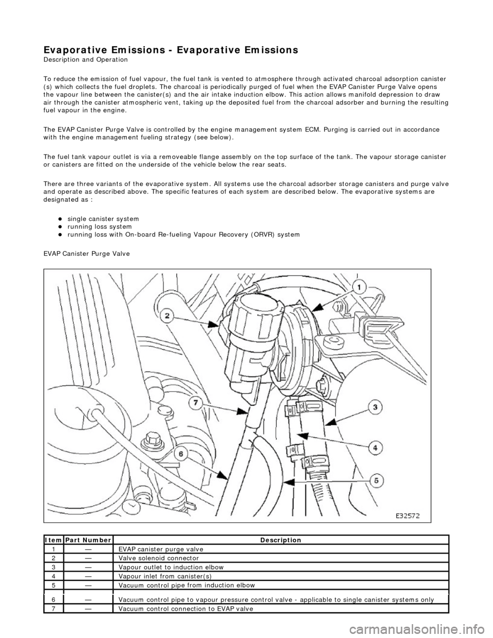
EVAP Canister Purge Valve
Ite
m
Par
t
Number
De
scr
iption
1—EVAP canister purge v
alve
2—Valve s
olenoid connector
3—Vapour outlet to indu
ction elbow
4—Vapour
inlet from canister(s)
5—Vacuum contro
l pi
pe from induction elbow
6—Vacuum contro
l pi
pe to vapour pressure control va
lve - applicable to single canister systems only
7—Vacuum
control connection to EVAP valve
Page 1151 of 2490
The evaporative l
oss flange assembly is fitted to the top of the tank via a seal and locking ring. The assembly is removeable
complete with the fitted components.
The vapour vent / rollover valve is a push fit via a sealing grommet. The fuel pump connector is push fitted and crimped
into a location tube on the underside of the flange.
It
em
Par
t Number
De
scription
1—Vapour vent /
rollover protection valve
2—Fue
l pump connector
3—Evaporative loss flange locking rin
g
Evaporative Flang
e Assembly
Page 1153 of 2490
tank vapou
r pressure.
Canister purge operation is as described in Evaporative Emissions Control.
Evaporative Flange Assembly
The evaporative loss flange assembly is fitted to the top of the tank via a seal and locking ring. The assembly is removeable
complete with the fitted components.
The vapour vent / rollover valve and pressure sensor are a pu sh fit via sealing grommets. The fuel pump connector is push
fitted and crimped into a location tu be on the underside of the flange.
It
em
Par
t Number
De
scription
1—Vapour vent /
rollover protection valve
2—Pres
sure sensor
3—Fue
l pump connector
4—Evaporative loss flange locking rin
g
Page 1155 of 2490

T
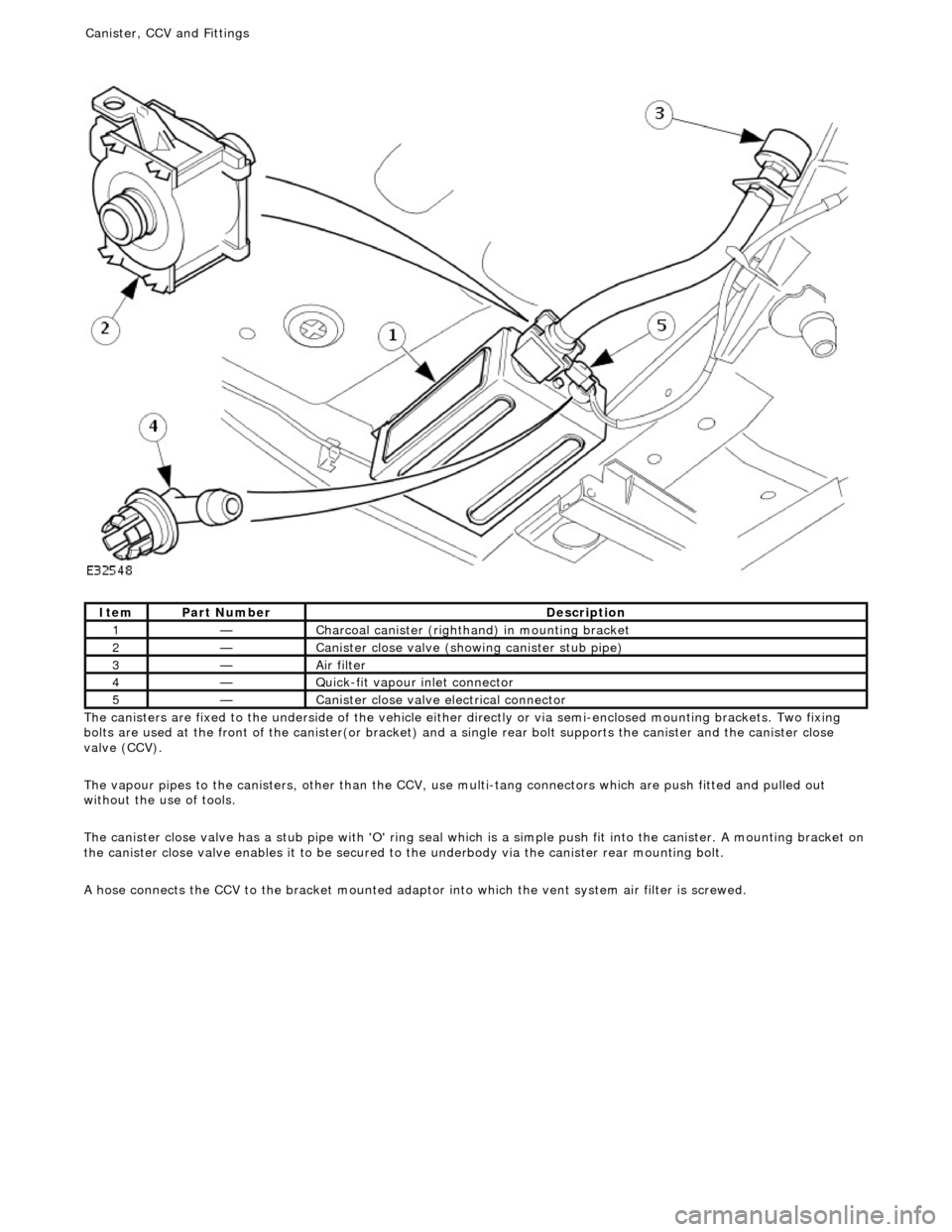
he canisters are fixed to the underside of the vehicle either
directly or via semi-enclosed mounting brackets. Two fixing
bolts are used at the front of the canister(or bracket) and a single rear bolt supports the canister and the canister close
valve (CCV).
The vapour pipes to the canisters, other than the CCV, use multi-tang connectors which are push fitted and pulled out
without the use of tools.
The canister close valve has a stub pipe with 'O' ring seal wh ich is a simple push fit into the canister. A mounting bracket on
the canister close valve enables it to be secured to the underbody via the canister rear mounting bolt.
A hose connects the CCV to the bracket mounted adaptor into which the vent system air filter is screwed.
It
em
Par
t Number
De
scription
1—C
harcoal canister (righthand) in mounting bracket
2—Cani
ster close valve (showi
ng canister stub pipe)
3—Ai
r filter
4—Q
uick-fit vapour inlet connector
5—Cani
ster close valve electrical connector
Canister, CCV an
d Fittings
Page 1158 of 2490

The fuel fil
ler cap is the same as
that used on non-ORVR systems.
The check valve assembly is a push fit into the end of the fuel filler tube and is accessible with the evaporative flange
removed. The valve has a light spring load ing and opens under the inflow of fuel.
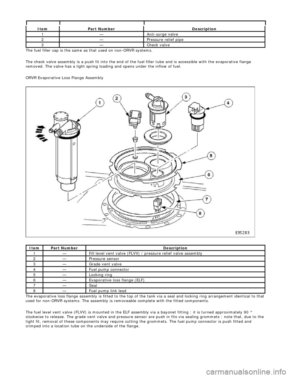
ORVR Evaporative Loss Flange Assembly
The evaporative loss flange assembly is fitted to the top of the tank via a seal and locking ring arrangement identical to that
used for non-ORVR systems. The assembly is re moveable complete with the fitted components.
The fuel level vent valve (FLVV) is mounted in the ELF assembly via a bayonet fitting : it is turned approximately 90 °
clockwise to release. The grade vent valve and pressure sensor are push in fits via sealing gromme ts : note that, due to the
tight fit, removal of these components may require cutting the grommets. The fuel pump connector is push fitted and
crimped into a location tube on the underside of the flange.
It e
m
Par
t
Number
De
scr
iption
1—An
ti-s
urge valve
2—Pressure rel
i
ef pipe
3—Check v
a
lve
It
e
m
Par
t
Number
De
scr
iption
1—Fi
ll
level vent valve (FLVV) /
pressure relief valve assembly
2—Pres
sure
sensor
3—Grade vent
valve
4—Fue
l
pump connector
5—Lockin
g rin
g
6—Evaporative loss flange (ELF)
7—Seal
8—F
u
el pump link lead