1998 JAGUAR X308 Connector
[x] Cancel search: ConnectorPage 1159 of 2490
T
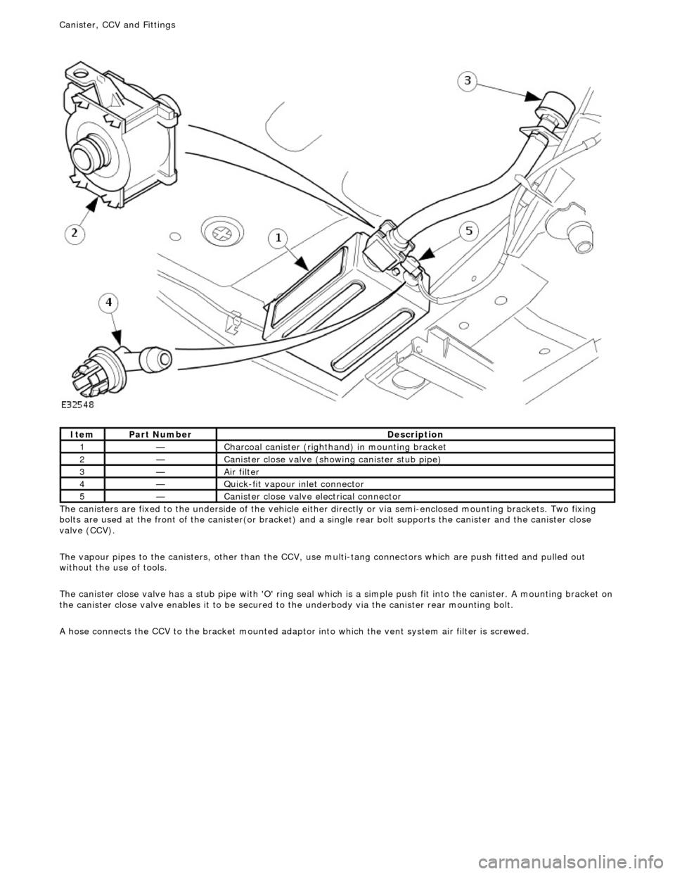
he canisters are fixed to the underside of the vehicle either
directly or via semi-enclosed mounting brackets. Two fixing
bolts are used at the front of the canister(or bracket) and a single rear bolt supports the canister and the canister close
valve (CCV).
The vapour pipes to the canisters, other than the CCV, use multi-tang connectors which are push fitted and pulled out
without the use of tools.
The canister close valve has a stub pipe with 'O' ring seal wh ich is a simple push fit into the canister. A mounting bracket on
the canister close valve enables it to be secured to the underbody via the canister rear mounting bolt.
A hose connects the CCV to the bracket mounted adaptor into which the vent system air filter is screwed.
It
em
Par
t Number
De
scription
1—C
harcoal canister (righthand) in mounting bracket
2—Cani
ster close valve (showi
ng canister stub pipe)
3—Ai
r filter
4—Q
uick-fit vapour inlet connector
5—Cani
ster close valve electrical connector
Canister, CCV an
d Fittings
Page 1161 of 2490
E
vaporative Emissions - Evaporative Emissions
D
iagnosis and Testing
Prelim
inary Inspection
1.
1. Vis
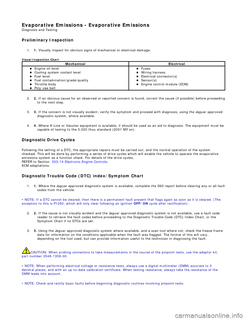
ually inspect for obvious signs of mechanical or electrical damage.
V
isual Inspection Chart
2.
2. If
an obvious cause for an observed or
reported concern is found, correct th e cause (if possible) before proceeding
to the next step.
3. 3. If the concern is not visually evident, verify the symptom and proceed with diagnosis, using the Jaguar approved
diagnostic system, where available.
4. 4. Where K-Line or Vacutec equipment is available, it should be used as an aid to diagnosis. The equipment must be
capable of testing to the 0.020 thou standard (2001 MY on).
Diagnostic Drive Cycles
Following th
e setting of a DTC, the appropriate repairs must
be carried out, and the normal operation of the system
checked. This will be done by performing a series of drive cycles which will enable the vehicle to operate the evaporative
emissions system as a function check. For details of the drive cycles,
REFER to Section 303
-1
4 Electronic Engine Controls
.
ECM adapt
ations.
Diagnostic Trouble Code
(D
TC) index/Symptom Chart
1.
1. Wh
ere the Jaguar approved diagnostic sy
stem is available, complete the S93 report before clearing any or all fault
codes from the vehicle.
• NOTE: If a DTC cannot be cleared, then there is a permanent fault present that flag s again as soon as it is cleared. (The
exception to this is P1260, which will only clear following an ignition OFF/ON cycle after rectification).
2. 2. If the cause is not visually evident and the Jaguar approv ed diagnostic system is not available, use a fault code
reader to retrieve the fault codes be fore proceeding to the Diagnostic Trou ble Code (DTC) Index Chart, or the
Symptom Chart if no DTCs are set.
3. 3. Using the Jaguar approved diagnostic system where available, and a scan tool where not, check the freeze frame
data for information on the conditions applicable when the fault was flagged. The format of this will vary,
depending on the tool used, but can pr ovide information useful to the technician in diagnosing the fault.
CAUTION: When probing connectors to take measurements in the course of the pinpoint tests, use the adaptor kit,
part number 3548-1358-00.
• NOTE: When performing electrical voltag e or resistance tests, always use a digital multimeter (DMM) accurate to 3
decimal places, and with an up-t o-date calibration certificate. When testing resistance, always take the resistance of the
DMM leads into account.
• NOTE: Check and rectify basic faults before beginning diagnostic ro utines involving pinpoint tests.
MechanicalElectrical
Engi
ne oil level
Coo
ling system coolant level
Fue
l level
Fuel contaminatio
n
/grade/quality
Throttle body Poly
-vee belt
F
uses
W
iring harness
E
lectrical connector(s)
Sens
or(s)
Engine
control module (ECM)
Page 1163 of 2490
Pinpoint Tests
P
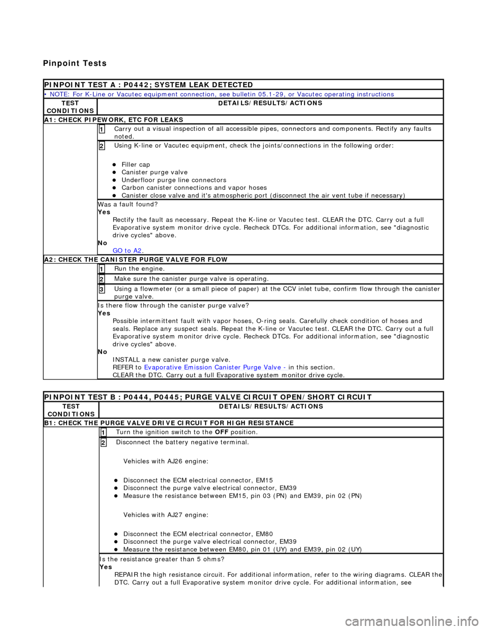
INPOINT TEST A : P0442; SYSTEM LEAK DETECTED
•
NOTE: For K-Line or Vacutec equipment connection, see bulletin 05.1-29, or Vacutec operating instructions
TE
ST
CONDITIONS
D
ETAILS/RESULTS/ACTIONS
A
1: CHECK PIPEWORK, ETC FOR LEAKS
Carr
y out a visual inspection of all accessible pipes, connectors and components. Rectify any faults
noted.
1
U
sing K-line or Vacutec equipment, check the
joints/connections in the following order:
Fi
ller cap
Cani
ster purge valve
Underfl
oor purge line connectors
Carbon
canister connections and vapor hoses
Cani
ster close valve and it's atmospheric port (disconnect the air vent tube if necessary)
2
Was
a fault found?
Yes Rectify the fault as necessary. Re peat the K-line or Vacutec test. CLEAR the DTC. Carry out a full
Evaporative system monitor drive cycle. Recheck DT Cs. For additional information, see "diagnostic
drive cycles" above.
No GO to A2
.
A2: CHECK
THE CA
NISTER PURGE VALVE FOR FLOW
Ru
n the engine.
1
Make sure the canister purge
valve is operating.
2
Using a flowmeter
(or a small piece
of paper) at the CCV inlet tube, confirm flow through the canister
purge valve.
3
Is th
ere flow through the canister purge valve?
Yes Possible intermittent faul t with vapor hoses, O-ring seals. Carefully check condition of hoses and
seals. Replace any suspect seals. Repeat the K-line or Vacutec test. CLEAR the DTC. Carry out a full
Evaporative system monitor drive cycle. Recheck DT Cs. For additional information, see "diagnostic
drive cycles" above.
No INSTALL a new canister purge valve.
REFER to Evaporative Emission Canister Purge Valve
- in t
his section.
CLEAR the DTC. Carry out a full Evap orative system monitor drive cycle.
P
INPOINT TEST B : P0444, P0445; PURGE VALVE CIRCUIT OPEN/SHORT CIRCUIT
TE
ST
CONDITIONS
D
ETAILS/RESULTS/ACTIONS
B1: CHECK
THE PURGE VALVE DRIV
E CIRCUIT FOR HIGH RESISTANCE
Turn the ignition swi
tch to the OFF
position.
1
Di
sconnect the battery negative terminal.
Vehicles with AJ26 engine:
Disc
onnect the ECM electrical connector, EM15
Di
sconnect the purge valve electrical connector, EM39
Meas
ure the resistance between EM15,
pin 03 (PN) and EM39, pin 02 (PN)
Vehicles with AJ27 engine:
Disc
onnect the ECM electrical connector, EM80
Di
sconnect the purge valve electrical connector, EM39
Meas
ure the resistance between EM80, pin 01 (UY) and EM39, pin 02 (UY)
2
Is th
e resistance greater than 5 ohms?
Yes REPAIR the high resistance circuit. For additional information, refer to the wiring diagrams. CLEAR the
DTC. Carry out a full Evaporative system monitor drive cycle. For additional information, see
Page 1164 of 2490
"d
iagnostic drive cycles" above.
No GO to B2
.
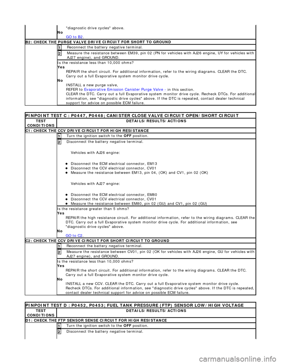
B2: CHECK THE PURGE VALVE DR
IV
E CIRCUIT FOR SHORT TO GROUND
Re
connect the battery negative terminal.
1
Meas
ure t
he resistance between EM39, pin 02 (PN for vehicles with AJ26
engine, UY for vehicles with
AJ27 engine), and GROUND.
2
Is t
he resistance less than 10,000 ohms?
Yes REPAIR the short circuit. For addi tional information, refer to the wiring diagrams. CLEAR the DTC.
Carry out a full Evaporative system monitor drive cycle.
No INSTALL a new purge valve,
REFER to Evaporative Emission Canister Purge Valve
- in thi
s section.
CLEAR the DTC. Carry out a full Evaporative system monitor drive cycle. Recheck DTCs. For additional
information, see "diagnostic drive cycles" above. If the DTC is repeated, contact dealer technical
support for advice on possible ECM failure.
PI
NPOINT TEST C : P0447, P0448; CANISTER CLOSE VALVE CIRCUIT OPEN/SHORT CIRCUIT
TE
S
T
CONDITIONS
D E
TAILS/RESULTS/ACTIONS
C1
: CH
ECK THE CCV DRIVE CIRCUIT FOR HIGH RESISTANCE
Turn the ignition swi
t
ch to the
OFF position.
1
Disc
onnect the battery negative terminal.
Vehicles with AJ26 engine:
Disc onne
ct the ECM electrical connector, EM13
Di
sc
onnect the CCV electrical connector, CV01
Meas
ure t
he resistance between EM13, pi
n 04, (OK) and CV1, pin 02 (OK)
Vehicles with AJ27 engine:
Disc onne
ct the ECM electrical connector, EM80
Di
sc
onnect the CCV electrical connector, CV01
Meas
ure t
he resistance between EM80,
pin 02 (GU) and CV1, pin 02 (GU)
2
Is the res
istance greater than 5 ohms?
Yes REPAIR the high resistance circuit. For additional information, refer to the wiring diagrams. CLEAR the
DTC. Carry out a full Evaporative system monitor drive cycle. For additional information, see
"diagnostic drive cycles" above.
No GO to C2
.
C2: CH
ECK THE CCV DRIVE CIRCUI
T FOR SHORT CIRCUIT TO GROUND
Re
connect the battery negative terminal.
1
Meas
ure t
he resistance between CV01,
pin 02 (OK for vehicles with AJ26 engine, GU for vehicles with
AJ27 engine), and GROUND.
2
Is t
he resistance less than 10,000 ohms?
Yes REPAIR the short circuit. For addi tional information, refer to the wiring diagrams. CLEAR the DTC.
Carry out a full Evaporative system monitor drive cycle.
No INSTALL a new CCV. CLEAR the DTC. Carry out a fu ll Evaporative system monitor drive cycle.
Recheck DTCs. For additional inform ation, see "diagnostic drive cycles" above. If the DTC is repeated,
contact dealer technical support for advice on possible ECM failure.
P INPOINT TES
T D : P0452, P0453; FUEL TANK
PRESSURE (FTP) SENSOR LOW/HIGH VOLTAGE
TES
T
CONDITIONS
DE
TAILS/RESULTS/ACTIONS
D
1:
CHECK THE FTP SENSOR SENSE CIRCUIT FOR HIGH RESISTANCE
Turn the ignition swi
t
ch to the OFF
position.
1
Disc
onnect the battery negative terminal.
2
Page 1165 of 2490
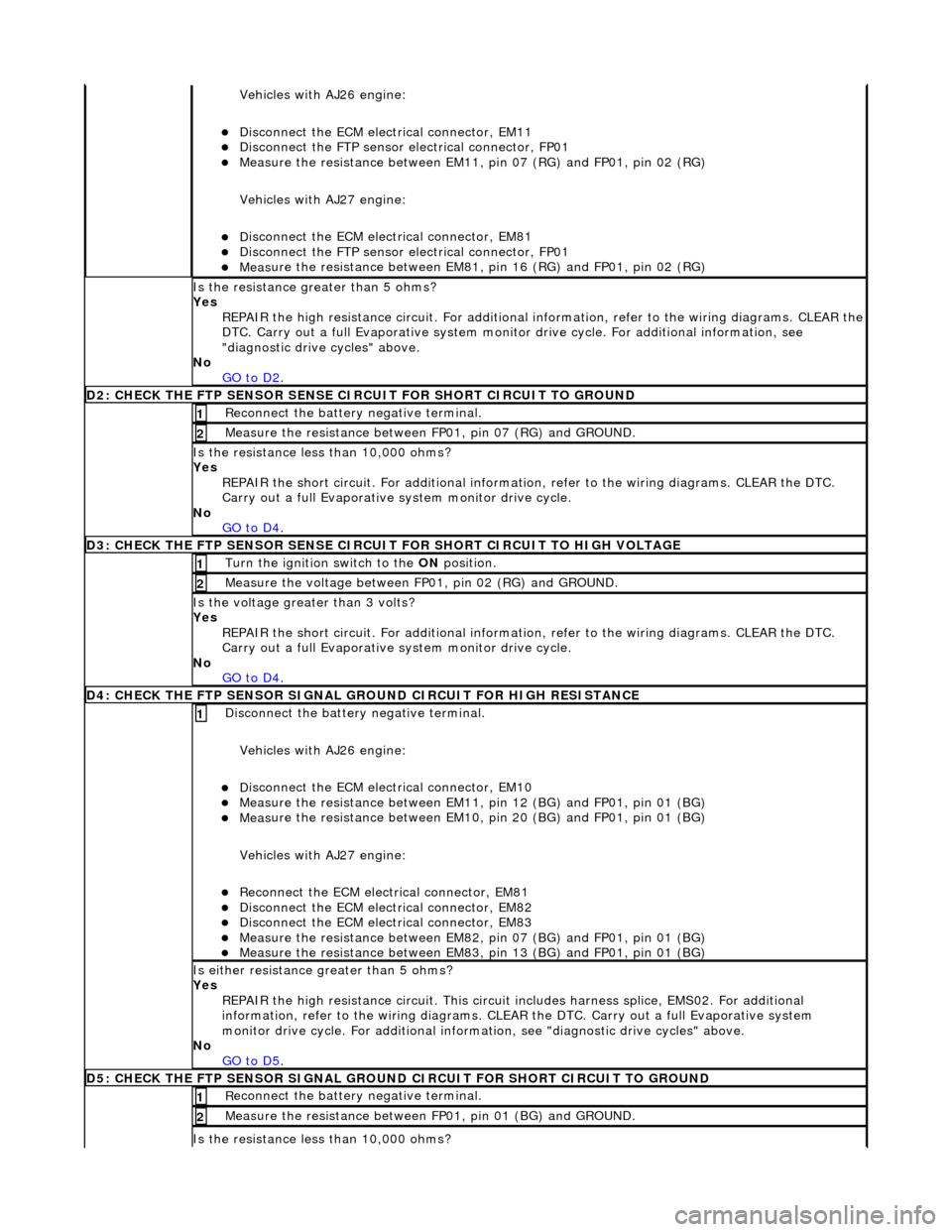
Vehicles with AJ26 en
gine:
D
isconnect the ECM electrical connector, EM11
Di
sconnect the FTP sensor electrical connector, FP01
Meas
ure the resistance between EM11,
pin 07 (RG) and FP01, pin 02 (RG)
Vehicles with AJ27 engine:
D
isconnect the ECM electrical connector, EM81
Di
sconnect the FTP sensor electrical connector, FP01
Meas
ure the resistance between EM81,
pin 16 (RG) and FP01, pin 02 (RG)
Is th
e resistance greater than 5 ohms?
Yes REPAIR the high resistance circuit. For additional information, refer to the wiring diagrams. CLEAR the
DTC. Carry out a full Evaporative system monitor drive cycle. For additional information, see
"diagnostic drive cycles" above.
No GO to D2
.
D2: CHECK
THE FTP SENSOR SENSE CI
RCUIT FOR SHORT CIRCUIT TO GROUND
R
econnect the battery negative terminal.
1
Meas
ure the resistance between
FP01, pin 07 (RG) and GROUND.
2
Is
the resistance less than 10,000 ohms?
Yes REPAIR the short circuit. For addi tional information, refer to the wiring diagrams. CLEAR the DTC.
Carry out a full Evaporative system monitor drive cycle.
No GO to D4
.
D3: CHECK
THE FTP SENSOR SENSE CIRCUI
T FOR SHORT CIRCUIT TO HIGH VOLTAGE
Turn the ignition swi
tch to the ON
position.
1
Measure the
voltage between FP
01, pin 02 (RG) and GROUND.
2
Is th
e voltage greater than 3 volts?
Yes REPAIR the short circuit. For addi tional information, refer to the wiring diagrams. CLEAR the DTC.
Carry out a full Evaporative system monitor drive cycle.
No GO to D4
.
D
4: CHECK THE FTP SENSOR SIGNAL GROUND CIRCUIT FOR HIGH RESISTANCE
Di
sconnect the battery negative terminal.
Vehicles with AJ26 engine:
D
isconnect the ECM electrical connector, EM10
Meas
ure the resistance between EM11, pin 12 (BG) and FP01, pin 01 (BG)
Meas
ure the resistance between EM10, pin 20 (BG) and FP01, pin 01 (BG)
Vehicles with AJ27 engine:
Re
connect the ECM electrical connector, EM81
D
isconnect the ECM electrical connector, EM82
D
isconnect the ECM electrical connector, EM83
Meas
ure the resistance between EM82, pin 07 (BG) and FP01, pin 01 (BG)
Meas
ure the resistance between EM83, pin 13 (BG) and FP01, pin 01 (BG)
1
Is either resi
stance
greater than 5 ohms?
Yes REPAIR the high resistance circui t. This circuit includes harness splice, EMS02. For additional
information, refer to the wiring diagrams. CLEAR the DTC. Carry out a full Evaporative system
monitor drive cycle. For additional informat ion, see "diagnostic drive cycles" above.
No GO to D5
.
D5:
CHECK THE FTP SENSOR SIGNAL GROUND
CIRCUIT FOR SHORT CIRCUIT TO GROUND
R
econnect the battery negative terminal.
1
Meas
ure the resistance between
FP01, pin 01 (BG) and GROUND.
2
Is
the resistance less than 10,000 ohms?
Page 1169 of 2490
Evaporative Emissions - Evaporative Emission Canister Purg
e Valve
Re
moval and Installation
Remov
al
Installation
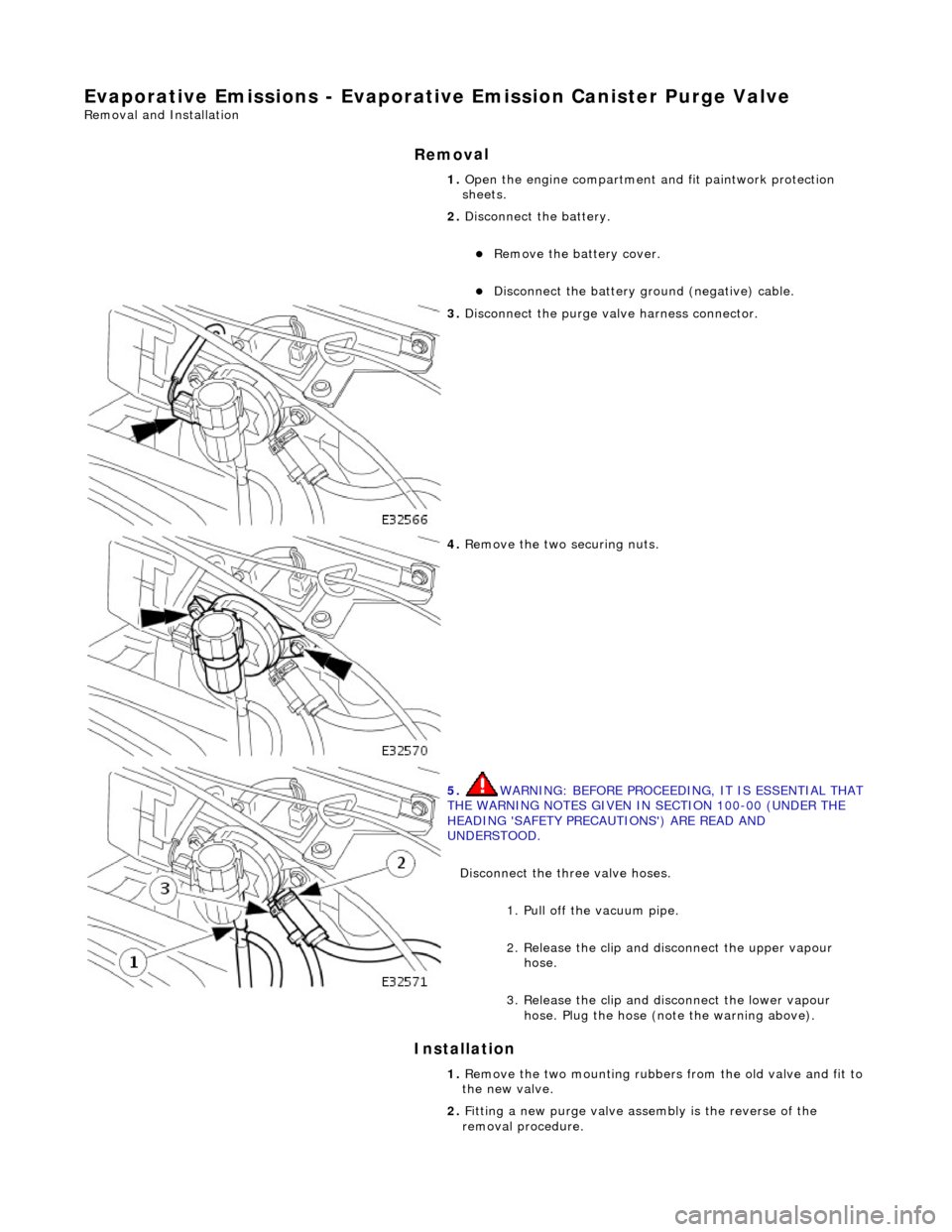
1. O
pen the engine compartment and fit paintwork protection
sheets.
2. Disconnect the battery.
R
emove the battery cover.
Di
sconnect the battery ground (negative) cable.
3. Di
sconnect the purge valve harness connector.
4. R
emove the two securing nuts.
5. WARNING: B
EFORE PROCEEDING, IT IS ESSENTIAL THAT
THE WARNING NOTES GIVEN IN SECTION 100-00 (UNDER THE
HEADING 'SAFETY PRECAUTIONS') ARE READ AND
UNDERSTOOD.
Disconnect the three valve hoses.
1. Pull off the vacuum pipe.
2. Release the clip and di sconnect the upper vapour
hose.
3. Release the clip and disconnect the lower vapour hose. Plug the hose (note the warning above).
1. R
emove the two mounting rubbers from the old valve and fit to
the new valve.
2. Fitting a new purge valve asse mbly is the reverse of the
removal procedure.
Page 1173 of 2490
Evapor
ative Emissions - Fuel Va
por Vent Valve Housing Seal
Remov
al and Installation
Re
moval
• NO
TE: The Removal and Installation procedur
es below show one type of flange but are applicable to the other evaporative loss systems
described.
Special To
ol(s)
Lock
Ring Wrench - Fuel Tank Flange
412-070 (JD 174)
1. Remove battery. Refer to 86.15.01.
2. WARNING: BEFORE PROCEEDING, IT IS ESSENTIAL THAT THE
WARNING NOTES GIVEN IN SECTIO N 100-00 (UNDER THE HEADING
'SAFETY PRECAUTIONS') ARE READ AND UNDERSTOOD.
Remove fuel tank assembly for access. Refer to operation 19.55.01.
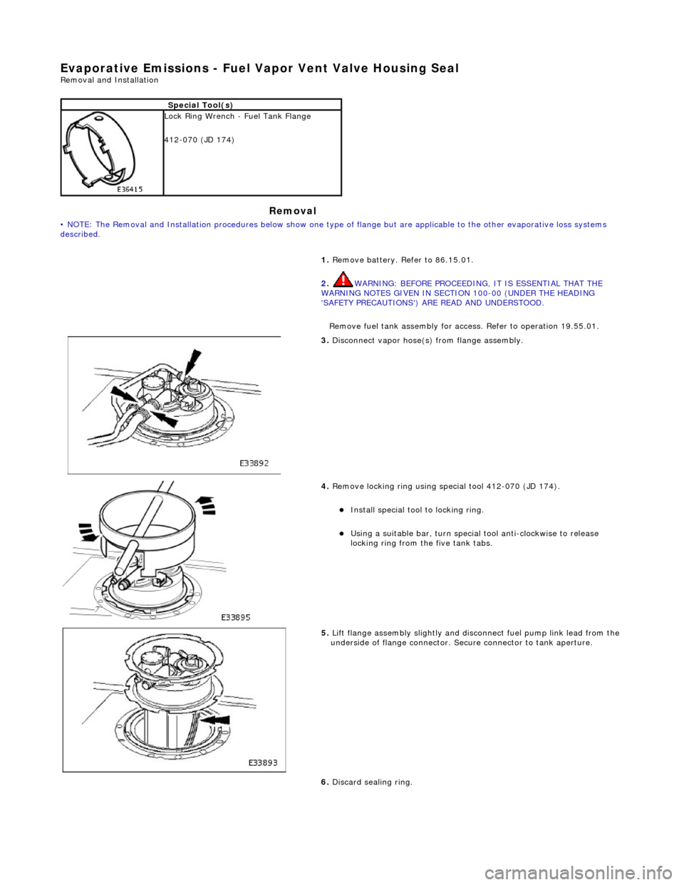
3. Discon
nect vapor hose(s) from flange assembly.
4. Remov
e locking ring using special tool 412-070 (JD 174).
Insta
ll special tool to locking ring.
Usi
ng a suitable bar, turn special tool anti-clockwise to release
locking ring from the five tank tabs.
5. Lift
flange assembly slightly and disconnect fuel pump link lead from the
underside of flange connector. Secure connector to tank aperture.
6. Discard sealing ring.
Page 1174 of 2490
Installation
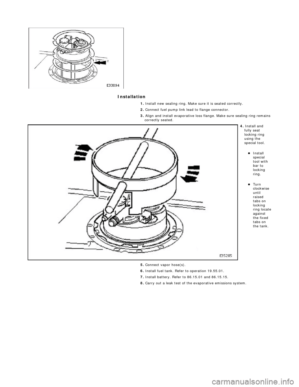
1.
Insta ll n
ew sealing ring. Make sure it is seated correctly.
2. Connect fuel pump link lead to flange connector.
3. Align and install evaporative loss flange. Make sure sealing ring remains
correctly seated.
4. Insta ll a
nd
fully seat
locking ring
using the
special tool.
Insta ll
special
tool with
bar t
o
locking
ring.
Turn
clock w
ise
until
raised
tabs on
locking
ring locate
against
the fixed
tabs on
the tank.
5. Connect vapor hose(s).
6. Install fuel tank. Refer to operation 19.55.01.
7. Install battery. Refer to 86.15.01 and 86.15.15.
8. Carry out a leak test of the evaporative emissions system.