Page 1043 of 2490
the
abutment bracket.
6. R
emove coolant hoses.
Inst
all suitable blanking plugs.
7. Re
lease connector from bracket
under LH side of assembly.
8. R
emove throttle body to indu
ction elbow securing bolts.
9. Remove throttle body from induction elbow.
1. Remove throttle body.
2. Discard gasket.
Cle
an mating faces.
Page 1044 of 2490
In
stallation
Bl
ank off inlet tract to prevent ingress of foreign matter.
10 . R
emove throttle cable and intake duct brackets.
1. Instal
l throttle cable an
d intake duct brackets.
2. Instal
l throttle.
Inst
al
l new gasket.
3. Install connector.
Page 1046 of 2490
8. Wh ere appropri
ate check kick
down setting is within
specification and reset if requ ired as detailed from step 6
(Installation).
PDU use
rs see 44.15.38
9. Conne ct
scantool.
R
e
ad 'Current Powertrain Data'.
D
i
splay PID 120F (pedal demand).
10 . NO
TE: Ensure that contact with switch does not result in
switch movement.
Push throttle pedal until light contact is made with kickdown
switch.
11. Spe
cified PID value = 3.66 to 3.76 volts (2F9 + or - A hex).
If
the value is outside these limits, proceed to step 9
(Installation).
If t he
value is within these limits, proceed to step 13
(Installation).
12. Pull carpet from around kickdown switch.
13. Disconnect kickdown switch flying lead connector (to avoid
cable twist as the switch is rotated).
Page 1047 of 2490
14
.
Adjust kickdown switch to th e value as defined in step 8
(Installation).
15. Reconnect kickdown flying lead connector and verify setting.
16. Install air cleaner cover / intake assembly; refer 19.10.30.
17. Check coolant level and top up if required.
18. Reconnect battery ground cable (IMPORTANT, see SRO
86.15.15 for further information).
Page 1059 of 2490

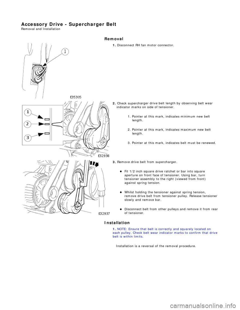
Ac
cessory Drive - Supercharger Belt
Re
moval and Installation
Remov
al
Installation
1.
Di
sconnect RH fa
n motor connector.
2. Check superch
arger dr
ive belt length by observing belt wear
indicator marks on side of tensioner.
1. Pointer at this mark, indicates minimum new belt length.
2. Pointer at this mark, indicates maximum new belt length.
3. Pointer at this mark, indi cates belt must be renewed.
3. R
emove drive belt from supercharger.
F
it 1/2 inch square drive ratchet or bar into square
aperture on front face of tensioner. Using bar, turn
tensioner assembly to the right (viewed from front)
against spring tension.
Wh
ilst holding the tensione
r against spring tension,
remove drive belt fr om tensioner pulley. Release tensioner
slowly and remove bar.
D
isconnect belt from
other pulleys and remove it from rear
of tensioner.
1. NOTE: Ensure that belt is correctly and squarely located on
each pulley. Check belt wear indicator marks to confirm that drive
belt is within limits.
Installation is a reversal of the removal procedure.
Page 1066 of 2490

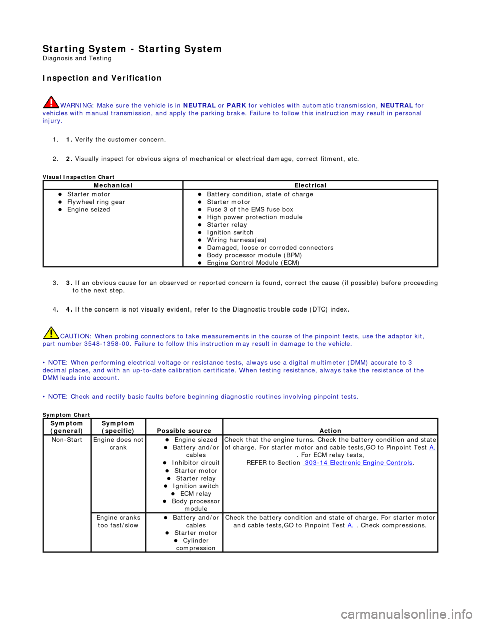
Starting System - Starting System
Diagn
osis and Testing
I
n
spection and Verification
W
A
RNING: Make sure
the vehicle is in NEUTRAL or PARK for vehicles with au tomatic transmission, NEUTRAL for
vehicles with manual transmissi on, and apply the parking brake. Failure to foll ow this instruction may result in personal
injury.
1. 1. Verify the customer concern.
2. 2. Visually inspect for obvious signs of mechanical or electrical damage, correct fitment, etc.
Vi
sual Inspection Chart
3.
3. If an obvi
ous cause for an observed or
reported concern is found, correct th e cause (if possible) before proceeding
to the next step.
4. 4. If the concern is not visually evident, refer to the Diagnostic trouble code (DTC) index.
CAUTION: When probing connectors to take measurements in the course of the pinpoint tests, use the adaptor kit,
part number 3548-1358-00. Failure to follow this in struction may result in damage to the vehicle.
• NOTE: When performing electrical voltag e or resistance tests, always use a digital multimeter (DMM) accurate to 3
decimal places, and with an up-t o-date calibration certificate. When testing resistance, always take the resistance of the
DMM leads into account.
• NOTE: Check and rectify basic faults before beginning diagnostic ro utines involving pinpoint tests.
Sym
ptom Chart
MechanicalElectrical
Starte
r motor
Flywheel
ring gear
Engine
s
eized
Batter
y condition, state of charge
Starte
r motor
F
u
se 3 of the EMS fuse box
High
power protec ti
on module
Starter relay Ignition switc
h
W
i
ring harness(es)
Damaged, loose or corroded connector
s
Body processor module (B
PM)
Engine
C
ontrol Module (ECM)
Sy
m
ptom
(
gene r
al)
Sy
m
ptom
(specific)
Possib l
e source
Acti
o
n
No
n
-Start
Engine does
not
crankEngine s
iezed
Batt
ery and
/or
cables
Inhibitor circuit St arte
r motor
Starter relay Ignition switc
h
ECM relay Body processor
modu le
Check that
the engine turns. Check the battery condition and state
of charge. For starter motor and ca ble tests,GO to Pinpoint Test A.
. For ECM relay
tests,
REFER to Section 303
-14
Electronic Engine Controls
.
Engine
c
ranks
too fast/slow
Batt ery and
/or
cables
St arte
r motor
Cy
linder
com
pression
Check the battery con
dition
and st
ate of charge. For starter motor
and cable tests,GO to Pinpoint Test A.
. Chec
k compressions.
Page 1067 of 2490

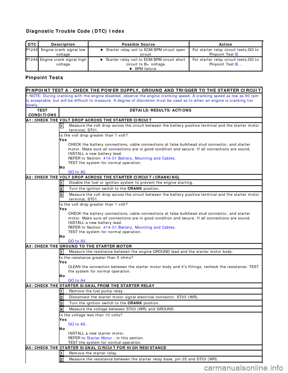
Pinpoint Tests
DT
C
De
scription
Possib
le Source
Acti
on
P1245Engine
crank signal low
voltage
Starter relay
coil to
ECM/BPM circuit open
circuit
F
or starter relay circuit tests,GO to
Pinpoint Test B.
.
P1246Engine
crank signal high
voltage
Starter relay
coil to ECM/BPM circuit short
circuit to B+ voltage
B
PM failure
F
or starter relay circuit tests,GO to
Pinpoint Test B.
.
P
INPOINT TEST A : CHECK THE
POWER SUPPLY, GROUND AND TRI GGER TO THE STARTER CIRCUIT
•
NOTE: During cranking with the engine disabled, observe the engine cranking speed. A cranking speed as low as 90 rpm
is acceptable, but will be difficult to measure. A degree of discretion must be used as to when an engine is cranking too
slowly.
TE
ST
CONDITIONS
D
ETAILS/RESULTS/ACTIONS
A1: CHECK
THE VOLT DROP AC
ROSS THE STARTER CIRCUIT
M
easure the volt drop across the circuit between the battery positive terminal and the starter motor
terminal, ST01.
1
Is the vol
t drop greater than 1 volt?
Yes CHECK the battery connections, cable connections at false bulkhead stud connector, and starter
motor. Make sure all connections are in good co ndition and secure. If all connections are sound,
INSTALL a new battery lead.
REFER to Section 414
-0
1 Battery, Mounting and Cables
.
TEST the system
for normal operation.
No GO to A2
.
A2: CHECK
THE VOLT DROP ACROSS
THE STARTER CIRCUIT (CRANKING)
Di
sable the fuel or ignition system to prevent the engine starting.
1
Turn the ignition swi
tch to the CRANK
position.
2
M
easure the volt drop across the circuit between the battery positive terminal and the starter motor
terminal, ST01.
3
Is the vol
t drop greater than 1 volt?
Yes CHECK the battery connections, cable connections at false bulkhead stud connector, and starter
motor. Make sure all connections are in good co ndition and secure. If all connections are sound,
INSTALL a new battery lead.
REFER to Section 414
-0
1 Battery, Mounting and Cables
.
TEST the system
for normal operation.
No GO to A3
.
A3:
CHECK THE GROUND TO THE STARTER MOTOR
Meas
ure the resistance between the engine GROUND lead and the starter motor body.
1
Is th
e resistance greater than 5 ohms?
Yes CLEAN the connection between the starter motor body and it's fittings, recheck the resistance. TEST
the system for normal operation.
No GO to A4
.
A4
: CHECK THE STARTER SIGNAL FROM THE STARTER RELAY
R
emove the fuel pump relay.
1
Di
sconnect the starter motor signal
electrical connector, ST03 (WR).
2
Turn the ignition swi
tch to the CRANK
position.
3
M
easure the voltage between ST03 (WR) and GROUND.
4
Is th
e voltage less than 10 volts?
Yes GO to A5
.
No
INSTALL a new starter motor.
REFER to Starter Motor
-
in t
his section.
TEST the system for normal operation.
A5
: CHECK THE STARTER SIGNAL CIRCUIT FOR HIGH RESISTANCE
R
emove the starter relay.
1
Meas
ure the resistance between the st
arter relay base, pin 05 and ST03 (WR).
2
Diagnostic Trouble Code (D
TC) Index
Page 1068 of 2490

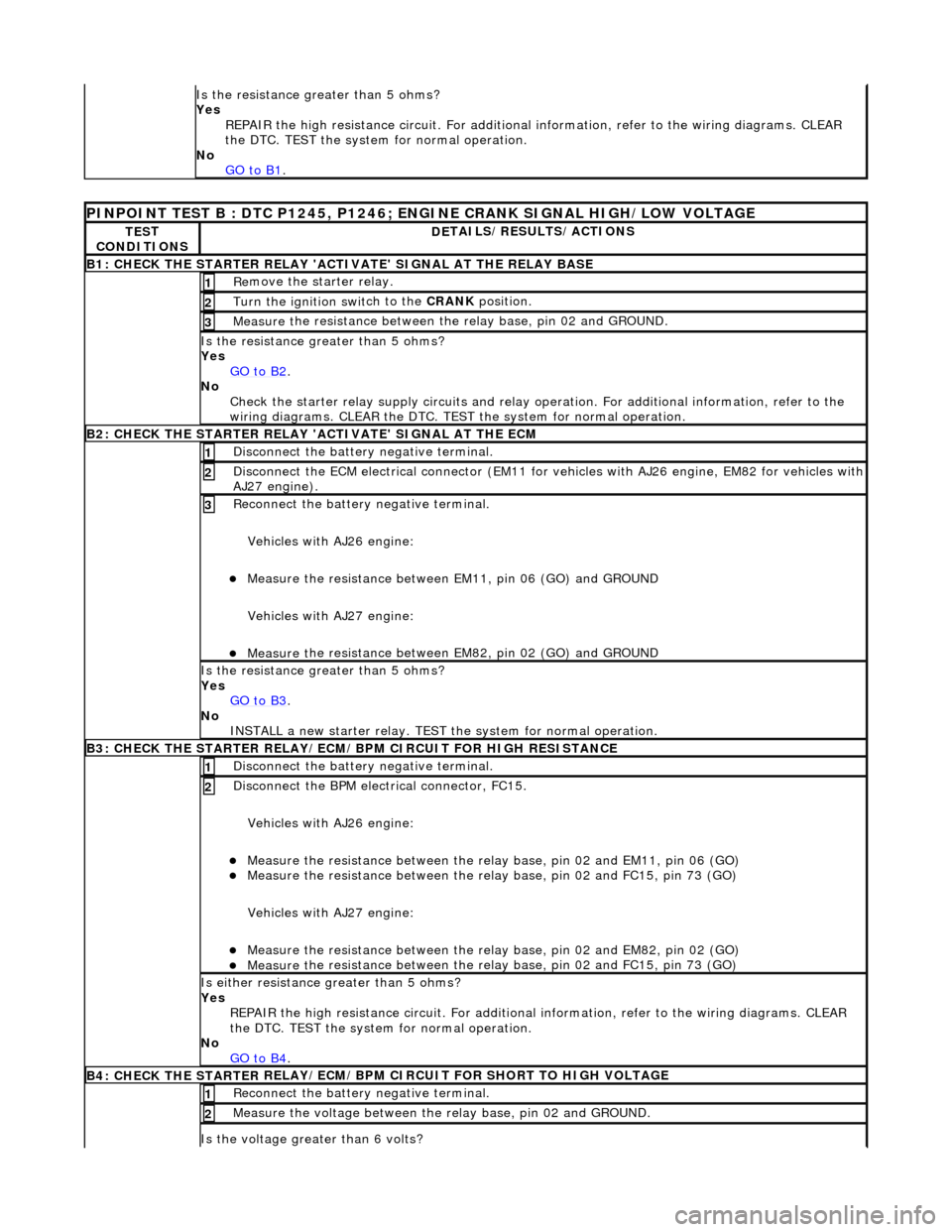
Is the res
istance greater than 5 ohms?
Yes REPAIR the high resistance circui t. For additional information, refer to the wiring diagrams. CLEAR
the DTC. TEST the system for normal operation.
No GO to B1
.
PINPOINT TES
T B : DTC P1245, P1246; ENGINE CRANK SIGNAL HIGH/LOW VOLTAGE
TE
S
T
CONDITIONS
D E
TAILS/RESULTS/ACTIONS
B1: CHECK
THE STARTER
RELAY 'ACTIV
ATE' SIGNAL AT THE RELAY BASE
Re
move the starter relay.
1
Turn the ignition swi
t
ch to the CRANK
position.
2
Measure t
he resistance between th
e relay base, pin 02 and GROUND.
3
Is the res
istance greater than 5 ohms?
Yes GO to B2
.
No Check t
he starter relay supply circui
ts and relay operation. For additi onal information, refer to the
wiring diagrams. CLEAR the DTC. TEST the system for normal operation.
B2: CHECK THE STARTER
RELAY 'A
CTIVATE' SIGNAL AT THE ECM
Disc
onnect the battery negative terminal.
1
D
i
sconnect the ECM electrical connector (EM11 for vehicles with AJ26 engine
, EM82 for vehicles with
AJ27 engine).
2
R e
connect the battery negative terminal.
Vehicles with AJ26 engine:
Meas ure t
he resistance between EM11, pin 06 (GO) and GROUND
Vehicles with AJ27 engine:
Meas ure t
he resistance between EM82, pin 02 (GO) and GROUND
3
Is th
e res
istance greater than 5 ohms?
Yes GO to B3
.
No
IN
STALL a new starter relay. TEST
the system for normal operation.
B3: CHECK THE STARTER
RELAY/ECM/BPM CIRCUIT FOR HIGH RESISTANCE
Di sc
onnect the battery negative terminal.
1
Disc
onne
ct the BPM electrical connector, FC15.
Vehicles with AJ26 engine:
Meas ure t
he resistance between the relay
base, pin 02 and EM11, pin 06 (GO)
Measure t
he resistance between the relay
base, pin 02 and FC15, pin 73 (GO)
Vehicles with AJ27 engine:
Meas ure t
he resistance between the relay
base, pin 02 and EM82, pin 02 (GO)
Measure t
he resistance between the relay
base, pin 02 and FC15, pin 73 (GO)
2
Is either resistance greater
than 5 ohms?
Yes REPAIR the high resistance circui t. For additional information, refer to the wiring diagrams. CLEAR
the DTC. TEST the system for normal operation.
No GO to B4
.
B4: CHECK THE STARTER
RE
LAY/ECM/BPM CIRCUIT FOR SHORT TO HIGH VOLTAGE
Re
connect the battery negative terminal.
1
Meas
ure t
he voltage between the
relay base, pin 02 and GROUND.
2
Is the volt
age greater than 6 volts?